relay MITSUBISHI ECLIPSE 1991 Owner's Manual
[x] Cancel search | Manufacturer: MITSUBISHI, Model Year: 1991, Model line: ECLIPSE, Model: MITSUBISHI ECLIPSE 1991Pages: 1216, PDF Size: 67.42 MB
Page 180 of 1216
![MITSUBISHI ECLIPSE 1991 Owners Manual 5-40BRAKES - Anti-lock Braking System Troubleshooting
E-7Abnormality of motor drive circuit
[Explanation]The ABS ECU illuminates the warning light for the
motor relay and motor in the following cases. MITSUBISHI ECLIPSE 1991 Owners Manual 5-40BRAKES - Anti-lock Braking System Troubleshooting
E-7Abnormality of motor drive circuit
[Explanation]The ABS ECU illuminates the warning light for the
motor relay and motor in the following cases.](/img/19/57104/w960_57104-179.png)
5-40BRAKES - Anti-lock Braking System Troubleshooting
E-7Abnormality of motor drive circuit
[Explanation]The ABS ECU illuminates the warning light for the
motor relay and motor in the following cases.
l When the motor relay does not function
lWhen there is trouble with the motor itself and it
does not revolve
[Hint]If there is motor operation noise when wheel speed
exceeds
Gkm/h (4mph) when starting up after the
engine is started, there is a broken or short circuitedmotor monitor wire.
lWhen the motor ground line is disconnected andthe motor does not revolve
l When the motor continues to revolve
Does the motor make a
YesBroken wire or short cir-noise when wheel speed
-cuit in motor monitor line
exceeds 6 km/h (4 mph)?
b
NoRepair the harness between HU and ECU.
emove the motor rela
ABS ECU
14A0105
Remove the motor relav and
check resistance values.
No.
85-No. 86:resistancevalue 30-60 QNo.30-No.87: no continui-
ty
Battery voltage is applied on
terminals No. 86 and No. 85
grounded
No. 30-No. 87: continuity
Yes
q Motor relay malfunction 1
Replace motor relay.I
Is pump motor ground con-netted normally?Connect ground wire.I
b
Does voltage between bodyNo
connector terminal 51 andIBroken wire in pumpmotor power circuit
ground indicate battery vol-
tage?1Repair the harness.
YesIs resistance between body
- No L Malfunction of harness
connector terminal No. 2 andbetween HU and ECU
No.26 30-60 ohms?b
YesRepair harness.
Motor drive circuit is normal.
Page 192 of 1216
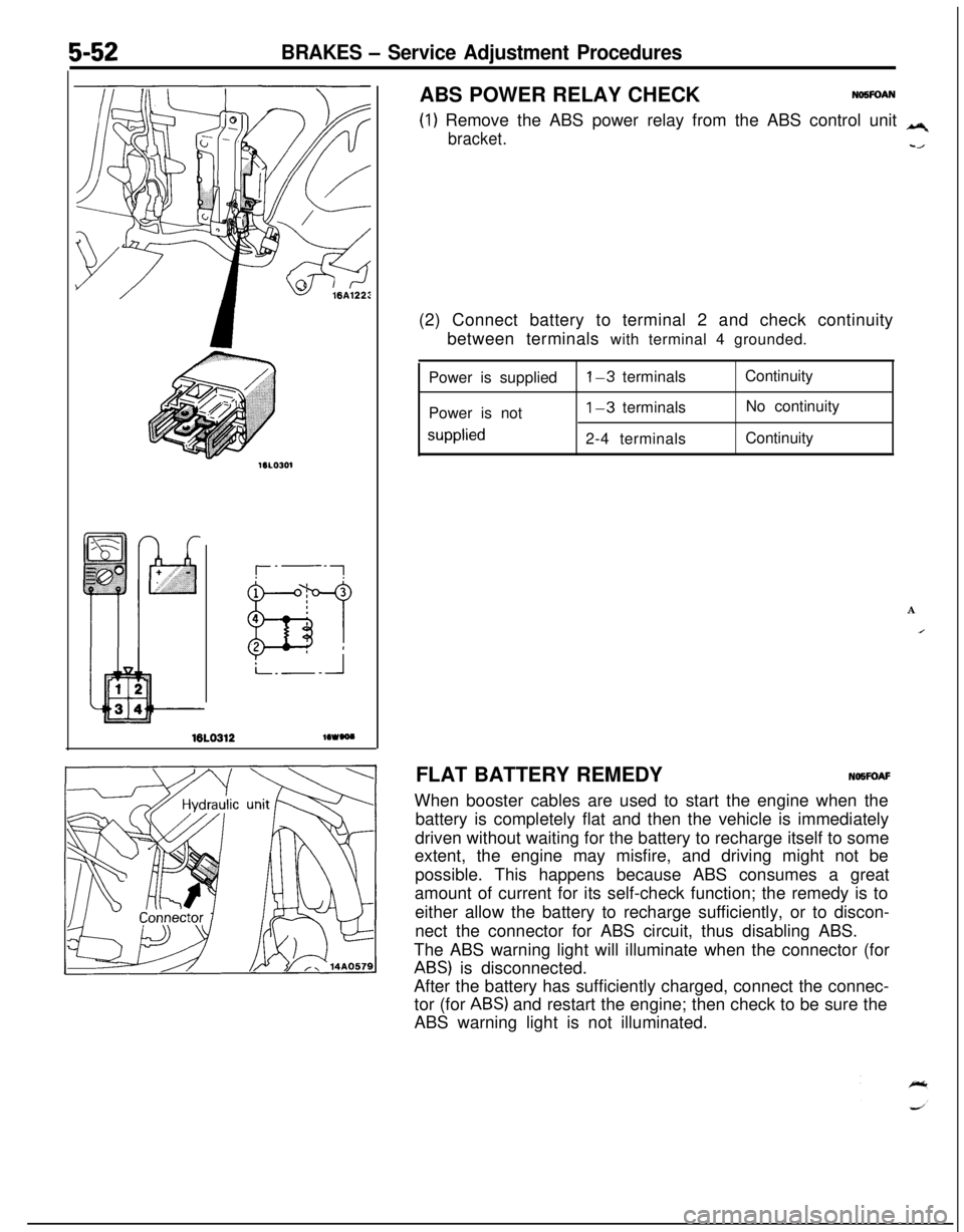
5-52BRAKES - Service Adjustment Procedures
16LO312lOWOO
(1) Remove the ABS power relay from the ABS control unit q
bracket.-/ABS POWER RELAY CHECK
NO5FOAN(2) Connect battery to terminal 2 and check continuity
between terminals with terminal 4 grounded.
Power is supplied
Power is not
supplied
l-3 terminals
1-3 terminals
2-4 terminalsContinuity
No continuity
Continuity
A
IFLAT BATTERY REMEDYNOWOAF
When booster cables are used to start the engine when the
battery is completely flat and then the vehicle is immediately
driven without waiting for the battery to recharge itself to some
extent, the engine may misfire, and driving might not be
possible. This happens because ABS consumes a great
amount of current for its self-check function; the remedy is to
either allow the battery to recharge sufficiently, or to discon-
nect the connector for ABS circuit, thus disabling ABS.
The ABS warning light will illuminate when the connector (for
ABS) is disconnected.
After the battery has sufficiently charged, connect the connec-
tor (for
ABS) and restart the engine; then check to be sure the
ABS warning light is not illuminated.
Page 193 of 1216
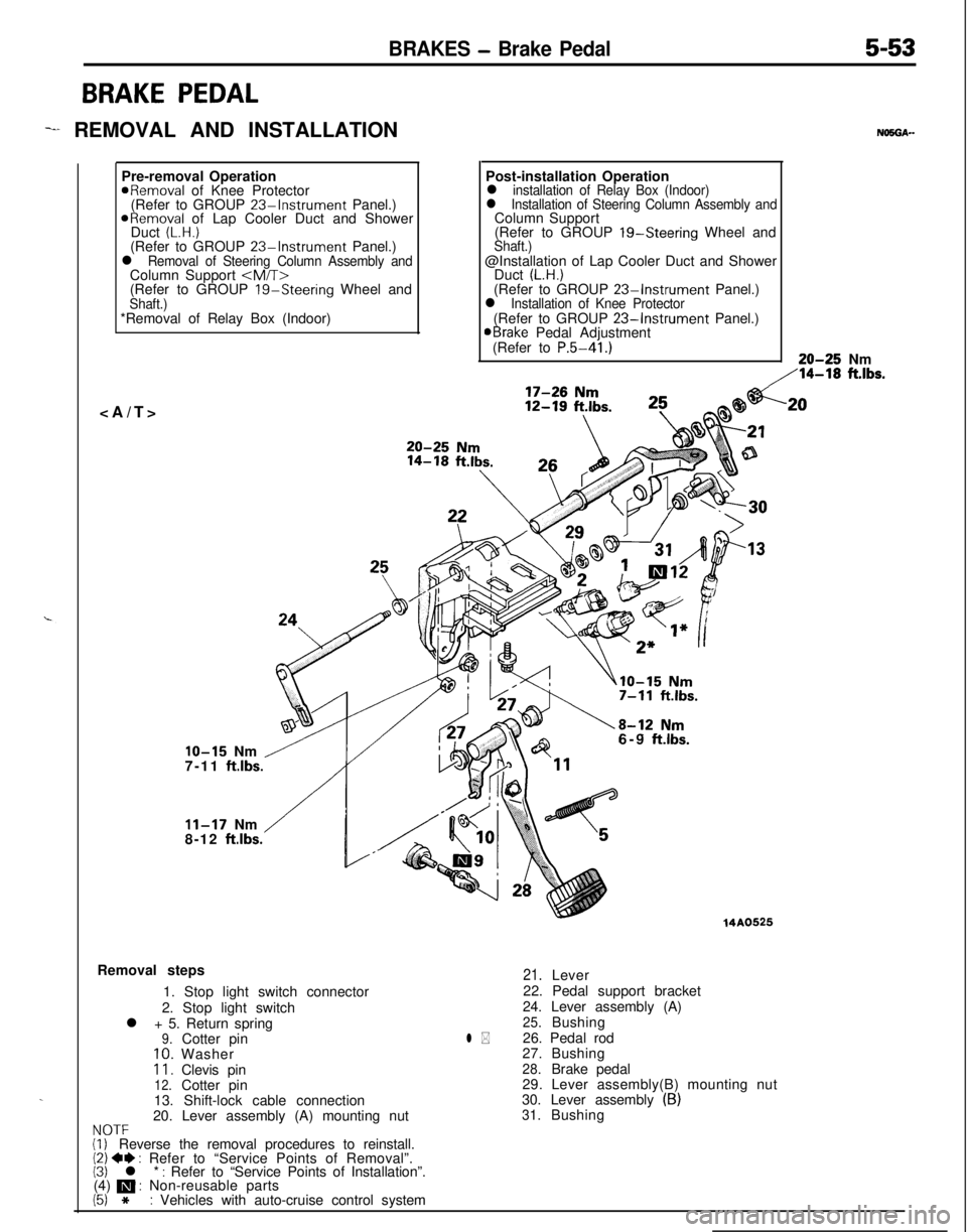
BRAKES - Brake Pedal5-53
BRAKE PEDAL
-I REMOVAL AND INSTALLATION
.Pre-removal Operation
aRemoval of Knee Protector
(Refer to GROUP 23%Instrument Panel.)
ORemoval of Lap Cooler Duct and Shower
Duct (L.H.)(Refer to GROUP 23-Instrument Panel.)l Removal of Steering Column Assembly andColumn Support
(Refer to GROUP
19-Steering Wheel andShaft.)*Removal of Relay Box (Indoor)
NO5OA--Post-installation Operation
l installation of Relay Box (Indoor)l Installation of Steering Column Assembly andColumn Support
(Refer to GROUP 19-Steering Wheel and
Shaft.)@Installation of Lap Cooler Duct and Shower
Duct
(L.H.)(Refer to GROUP 23-Instrument Panel.)l Installation of Knee Protector(Refer to GROUP 23-Instrument Panel.)aBrake Pedal Adjustment
(Refer to P.5-41.)20-25 Nm
,‘14-18 ft.lbs.
IO-15 Nm /7-11 ft.lbs.
/
11-17 Nm
8-12 ftlbs.6-9
ftlbs.Removal steps
1. Stop light switch connector
2. Stop light switch
l + 5. Return spring
9.Cotter pin10.Washer11.Clevis pin12.Cotter pin
13. Shift-lock cable connection
20. Lever assembly (A) mounting nut
NOTF(i, Reverse the removal procedures to reinstall.(2) 4I) : Refer to “Service Points of Removal”.(3) l * : Refer to “Service Points of Installation”.
(4) m : Non-reusable parts
(5) *: Vehicles with auto-cruise control system
14A0525
l *
21.Lever
22. Pedal support bracket
24. Lever assembly (A)
25.Bushing
26. Pedal rod
27.Bushing
28.Brake pedal
29. Lever assembly(B) mounting nut
30. Lever assembly
(B)31.Bushing
.20
Page 200 of 1216
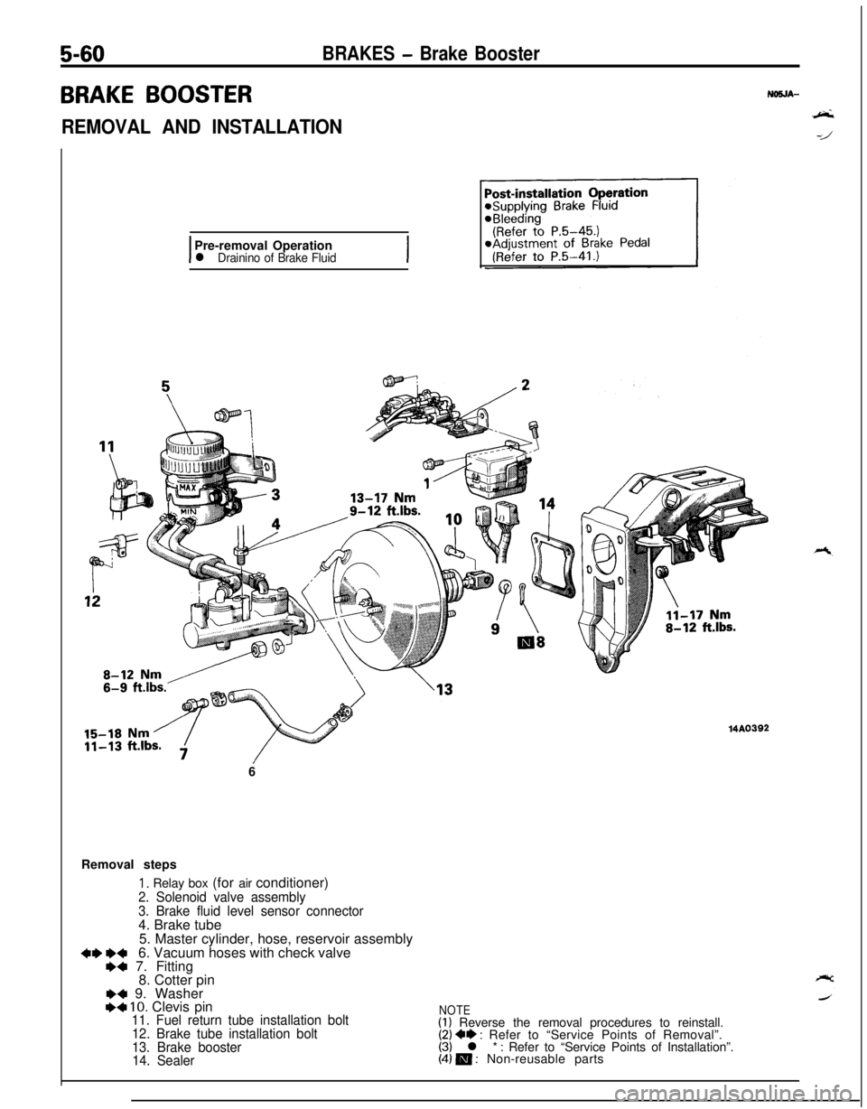
5-60BRAKES - Brake Booster
BRAKE BOOSTER
REMOVAL AND INSTALLATION
IPre-removal Operationl Drainino of Brake FluidI6
Removal steps
1. Relay box (for air conditioner)
2. Solenoid valve assembly
3. Brake fluid level sensor connector4. Brake tube
5. Master cylinder, hose, reservoir assembly
+I) e+6. Vacuum hoses with check valve+a 7. Fitting
8. Cotter pin
I)4 9. WasherI)4 10. Clevis pin11. Fuel return tube installation bolt
12. Brake tube installation bolt
13. Brake booster
14. Sealer
MA0392
NOTE(1) Reverse the removal procedures to reinstall.(2) ** : Refer to “Service Points of Removal”.(3) l * : Refer to “Service Points of Installation”.(4) m : Non-reusable parts
Page 217 of 1216
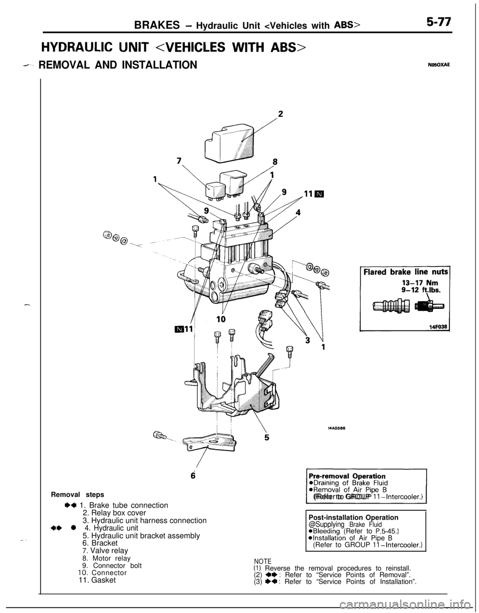
BRAKES - Hydraulic Unit
HYDRAULIC UNIT
--. REMOVAL AND INSTALLATION
6Removal steps
I)+ 1. Brake tube connection
2. Relay box cover
3. Hydraulic unit harness connection
~~ l 4. Hydraulic unit5. Hydraulic unit bracket assembly
6. Bracket
7. Valve relay
1(Refer to GROUP
II-Intercooler.)Post-installation Operation
@Supplying Brake FluidaBleeding (Refer to P.5-45.)@Installation of Air Pipe B(Refer to GROUP II-Intercooler.)8. Motor relay
9. Connector bolt
10. Connector
11. Gasket
NOTE(1) Reverse the removal procedures to reinstall.
(2) +e : Refer to “Service Points of Removal”.
(3) e+ : Refer to “Service Points of Installation”.
Page 218 of 1216
5-78BRAKES - Hydraulic Unit
SERVICE POINTS OF REMOVAL
4. REMOVAL OF HYDRAULIC UNITb-3Remove the installation nuts, and then take out the __
hydraulic unit upward.
Caution
1. The hydraulic unit is heavy, and so care should be
taken when removing it.2. The hydraulic unit is not to be disassembled; its
nuts and bolts should absolutely not be loosened.
3. The hydraulic unit must not be dropped or other-
wise subjected to impact shocks.
4.The hydraulic unit must not be turned upside downor laid on its side.
Aotor relay
16R0670
16Rl773
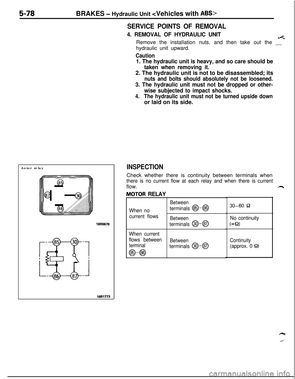
INSPECTIONCheck whether there is continuity between terminals when
there is no current flow at each relay and when there is currentflow.
JlOTOR RELAY
Between
When noterminals @-@I
current flowsBetween
terminals @I-@
When current
flows between
Between
terminal
terminals @--@
@-@
30-60 52
No continuity
(WQ)
Continuity
(approx. 0 8)
Page 219 of 1216
BRAKES -Hydraulic Unit
Jalve relay
16R0670
87a
16Rl772
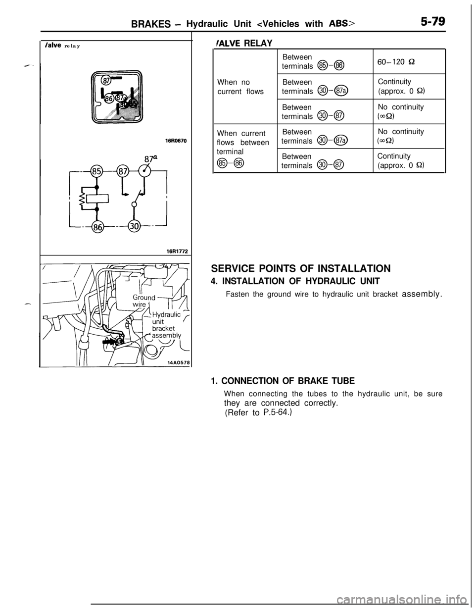
/ALVE RELAYBetween
terminals
@-@60-120 &2When noBetween
current flowsterminals
@I--@Continuity
(approx. 0 Q)Between
terminals
@J-QNo continuity(wQ2)When currentBetweenNo continuity
flows betweenterminals
@-@I(WQ)
terminal
@-@Between
terminals @--@Continuity
(approx. 0 S22)SERVICE POINTS OF INSTALLATION
4. INSTALLATION OF HYDRAULIC UNITFasten the ground wire to hydraulic unit bracket assembly.
1. CONNECTION OF BRAKE TUBEWhen connecting the tubes to the hydraulic unit, be sure
they are connected correctly.
(Refer to
P.5-64.)
Page 237 of 1216
CLUTCH - Clutch Pedal6-7
CLUTCH PEDAL
-. REMOVAL AND INSTALLATIONNOSPA-
.“-Pre-removal Operation
*Removal of the Lap Cooler Duct,Shower Duct (L.H.) and Knee Pro-tector (Refer to GROUP 23%lnstru-ment Panel.)*Removal of the Steering ColumnAssembly (Refer to GROUP 19-Steering Wheel and Shaft.)*Removal of the Relay Box (Indoor)
17-26 Nm
12-19 ft.lbs.
11-17 Nm
8-12 ft.lbs.
IO-15 Nm’ tl(i/\:/ Fl/Yv .1-m.---I- I I KIDS.Post-installation Operation
l installation of the Relay Box (Indoor)l installation of the Steering ColumnAssembly (Refer to GROUP 19-Steering Wheel and Shaft.)l installation of the Lap Cooler Duct,Shower Duct (L.H.) and Knee Pro-tector (Refer to GROUP 23 Instru-ment Panel.)l Adjustment of the Brake Pedal (Re-fer to GROUP 5-Service Adjust-ment Procedures.)aAdjustment of the Clutch Pedal (Re-
fer to P.6-5.)
:k -16
20-25 Nm
14-f8 ft.lbs.
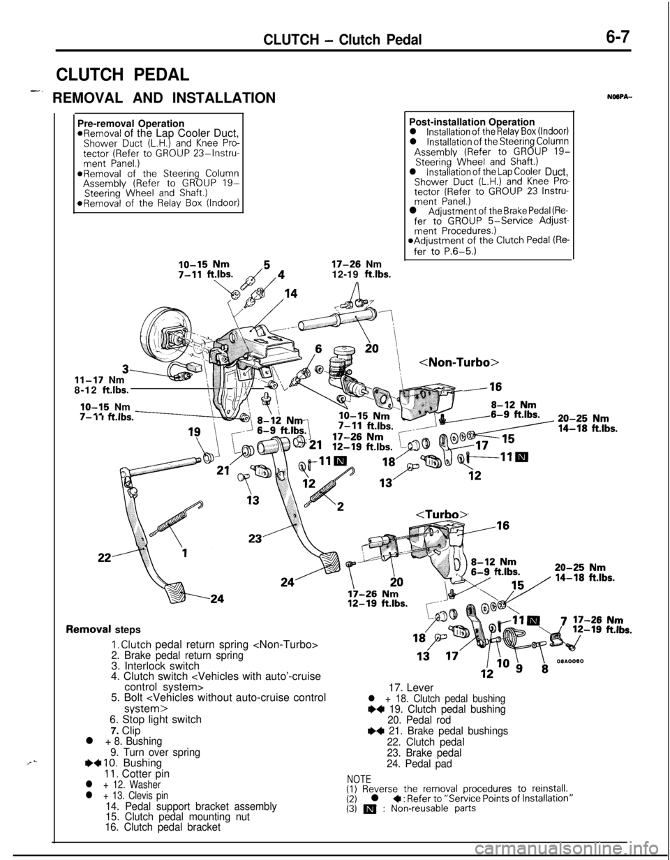
Removal steps
I, Clutch pedal return spring
4. Clutch switch
5. Bolt
7. Clip
l + 8. Bushing
9. Turn over spring
e+ IO. Bushing11. Cotter pinl + 12. Washerl + 13. Clevis pin14. Pedal support bracket assembly
15. Clutch pedal mounting nut
16. Clutch pedal bracket17. Lever
l + 18. Clutch pedal bushing~~ 19. Clutch pedal bushing
20. Pedal rod
e+ 21. Brake pedal bushings
22. Clutch pedal
23. Brake pedal
24. Pedal pad
NOTE(1) Reverse the removal procedures to reinstall.(2) l + : Refer to “Service Points of (3) m : Non-reusable parts
Page 253 of 1216

COOLING - Troubleshootina7-5
TRO,UBLESHOOTlNG
Symptom
OverheatProbable causeInsufficient engine coolant
Too high an anti-freeze concentrationRemedy
Replenish
Correct anti-freeze
concentration
Loose or broken drive belt
Replace
Inoperative electric cooling fan
Faulty thermosensor
Replace
Faulty electrical motorReplace
Faulty radiator fan relayReplace
Damaged or blocked (insufficiently ventilated) radiator finsCorrect
Water leaks
Damaged radiator core joint
Replace
Corroded or cracked hosesReplace
(radiator hose, heater hose, etc.)
Loose bolt or leaking gasket in water outlet fitting
(thermostat)
Loose water pump mounting bolt or leaking gasket
Faulty cap valve or setting of spring
Loose intake manifold bolts or leaking from gasket
Cracked intake manifold
Faulty automatic transaxle oil cooler operation
Blocked or collapsed hose and pipe
Loose hose and pipe connection
Faulty thermostat operation
Faulty water pump operation
Water passage clogged with slime or rust deposit or
foreign substanceCorrect or replace
Correct or replace
Replace
Retorque bolts or replace
gasket
Replace
Replace
Correct
Replace
Replace
Clean
Jo rise in temperatureFaulty thermostatReplace
Page 254 of 1216
7-6COOLING - Troubleshooting
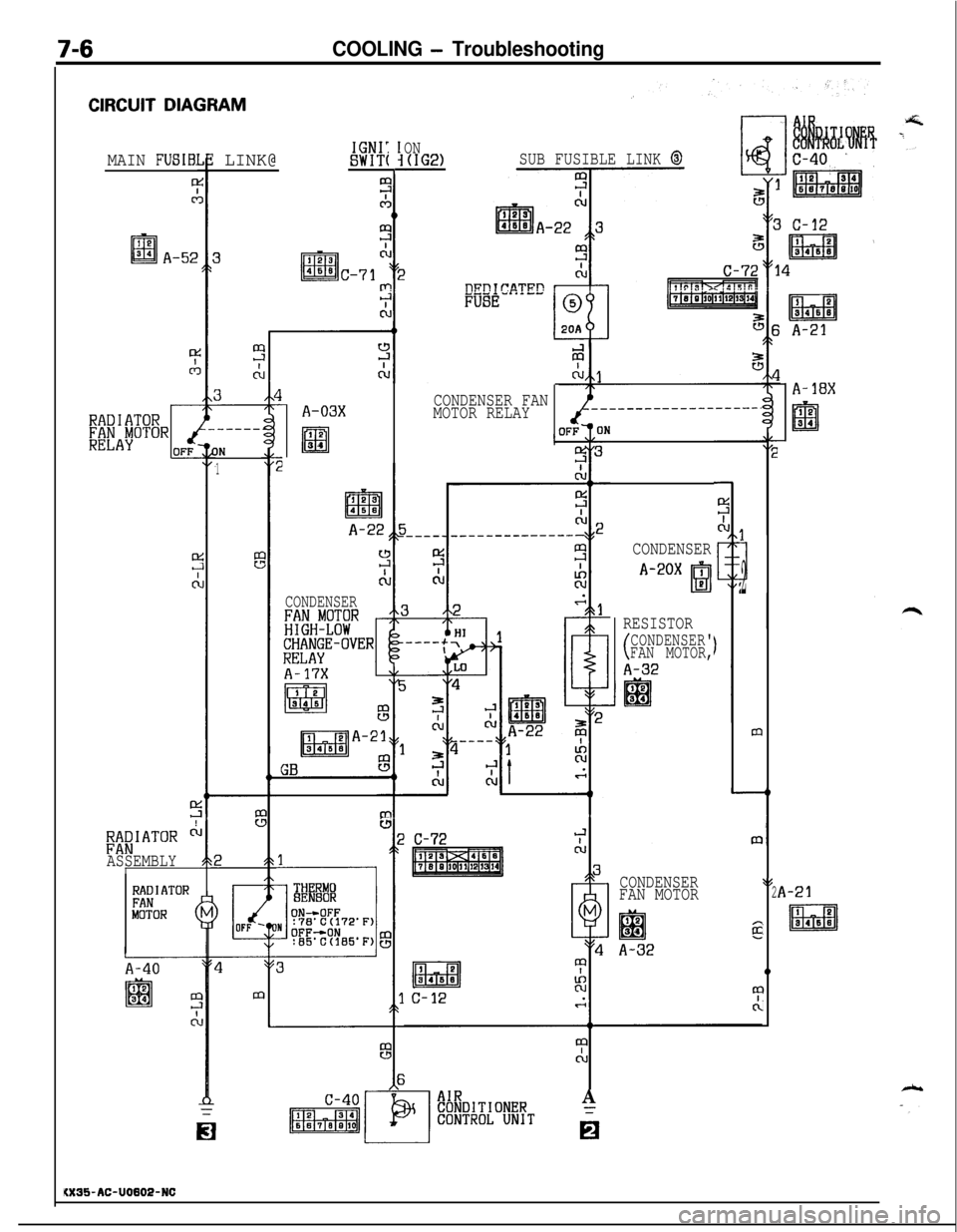
CIRCUIT DIAGRAM
ON(IG2)SUB FUSIBLE LINK @IGNI:SWIT(: LINK@MAIN FUSIB:
0
.-----
IN
1
A-18X
1CONDENSER
A-20X ,
I!31P2
RESISTOR
(CONDENSER'
FAN MOTOR,
A-32
m
A-21
IQ
Ed3B4SB
CONDENSER$l
FAN MOTOR2
12
lal34I
A-32
0
I
I
CONDENSER FAN
MOTOR RELAYA-03X
I 2lm34
A-22
CONDENSER
t----lTH RMOBE 80R
;;aIATOR ci
ASSEMBLY'
C-72
RADIATORFANMOTOR (
A-40
II
i0
A
6
KX35-AC-U0802-NC