MITSUBISHI ECLIPSE 1991 Workshop Manual
ECLIPSE 1991
MITSUBISHI
MITSUBISHI
https://www.carmanualsonline.info/img/19/57104/w960_57104-0.png
MITSUBISHI ECLIPSE 1991 Workshop Manual
Page 468 of 1216
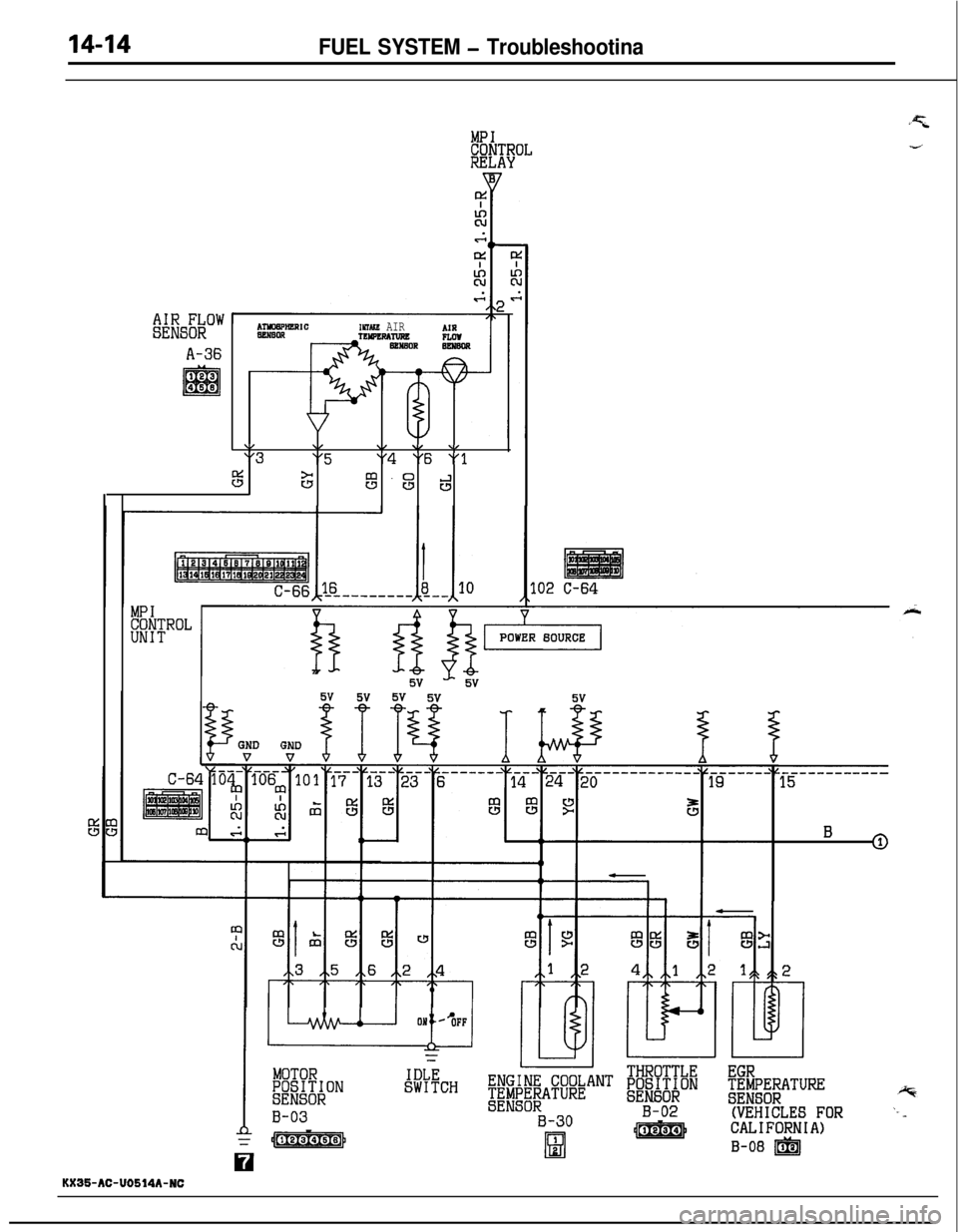
FUEL SYSTEM - Troubleshootina
MPICONTROLRELAY
k%sEiow
A-36
INMKR AIRAIRnormmcR RRRew
\/\/\/ \/ \/"3"5"4 "6 “13
sc3m -sd
.02 C-64
MPICONTROLUNIT
MOTORW3P;;ONIDLESWITCHBE"&@-j@"T f#nibi
B-03SENSORB-30B-02
=y-Qgg&q/Y[81
j-1
H
EGR;;i;;;ATURE
(VEHICLES FORCALIFORNIA)
B-06 m
KX35-AC-U0614A-NC
Page 469 of 1216
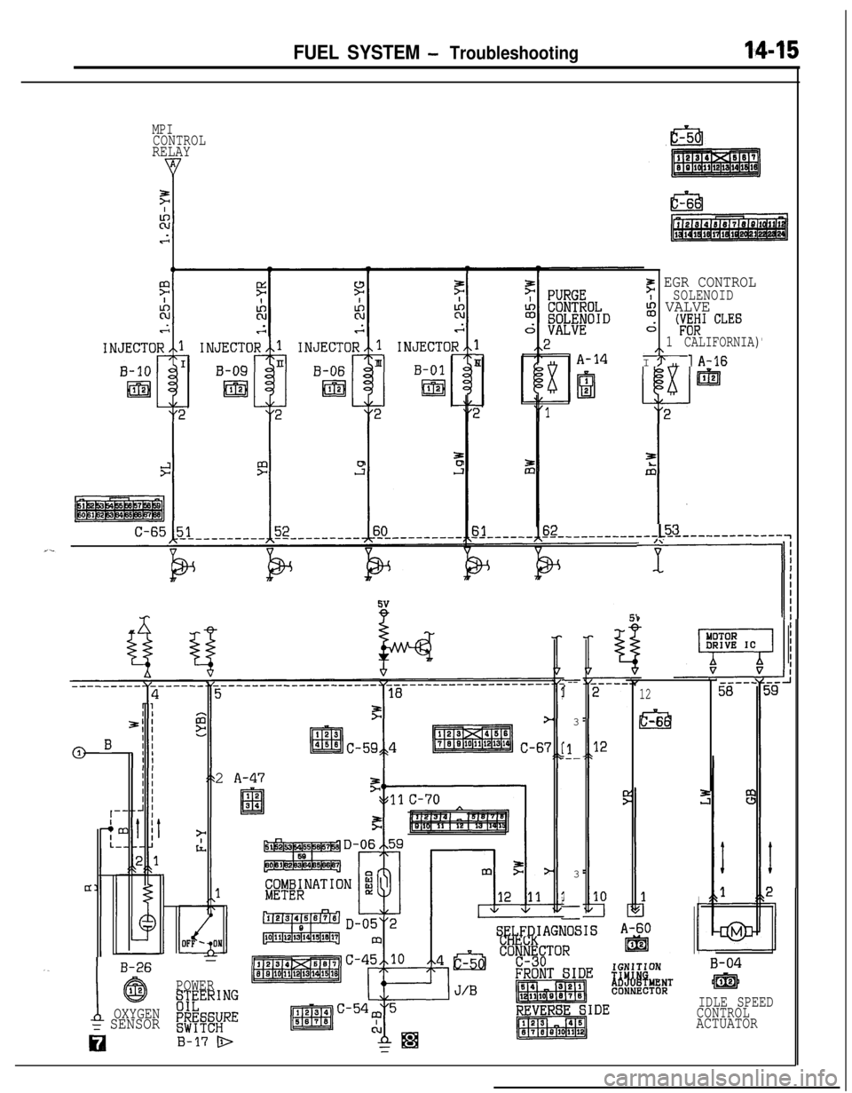
FUEL SYSTEM - Troubleshooting14-15
MPICONTROLRELAY
F EGR CONTROLSOLENOIDi VALVEd
'W CLES
”
1 CALIFORNIA)
I :‘, lo-16
xEDI
2
r3
.&
-L
,
8,
P
1
-.--I3
I1.--3
I--
12
al-62
A-47
SELFDIAGNOSISu
,.
1
B-26
@12
OXYGEN= SENSOR
cz1
B-04
Em
IDLE SPEED
CONTROL
ACTUATOR POWER
i;EERING
F'tF=;;RE
B-17 D
Page 471 of 1216
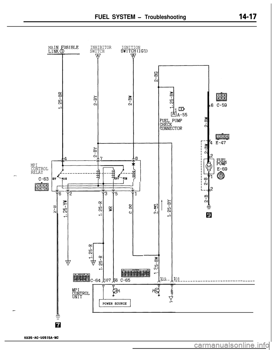
FUEL SYSTEM - Troubleshooting
INHIBITORSWITCHIGNITIONSWITCHtIGl)MALI:-
JSIBLE
FF- 0
I
;;;bKPUMP
:ONNECTOR
MPICONTROL
RELAY
J
1
3J
3
6
t?N
09----
ca
c:
C-64
c1r
6 C-6508,__-__--____--____-_-------------
KXIS-AC-UOSlSA-NC
Page 474 of 1216
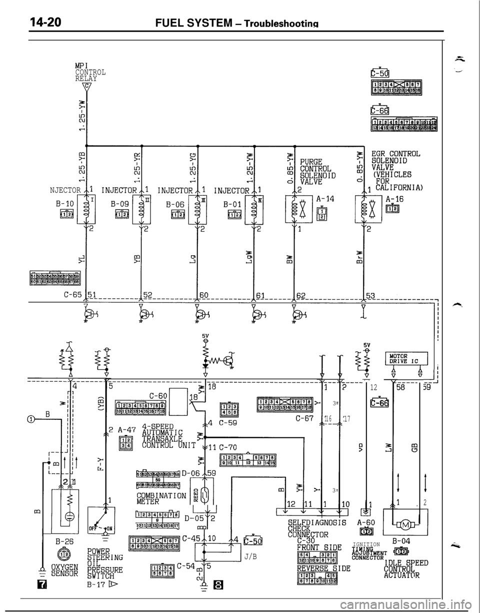
14-20FUEL SYSTEM - Troubleshootinn
MPICONTROLRELAY
gr
NJECTORrB-10
ml1
C-65
E
12
lc-6
E
.----)
17
5
7" [
TORIVE ICi-II
33
I
2
1
”_------------------------------_-------------)
pjiFBGgn<‘“,:
C-67
.--I3
16.--3
-----588
I
1 ,
I II I
f I,-- J ;
jmt itL-- -
i21I
B-26=
ry121314j5i61;fi;) D-05 2lolllll2lY3114115llell7~
‘7 1I Im
Ial-5
J/B
IGNITIONB-04
i6%hENT mQ
coNNEcToR~#~R'~EED
ACTUAT@R
Page 487 of 1216
FUEL SYSTEM - Troubleshooting
MPICONTROLRELAY
_ 1.25-R1
ck:IY
FtLocu;cc;2
SPEEDCONTROLI
ACTUATORd4
/\2
-Ii
x
JI---
A-32
mp (
6
0
i7--_
2
1
1 A-513
al-6
22i8--.
A-36
3
i9---4 2
m
7-rE-im5v
FWD !AWD
KX35-AC-UOBlBA-NC
1
1TIFF
[$G!6$$MPERATURE E#iiTTHROTTLE
(VEHICLES FORCALIFORNIA)
p%4F&mJRE !ggpN
B-30 1
l!!d
B-02
B-08 mj@&g
IDLESWITCH
B-05q
Page 492 of 1216
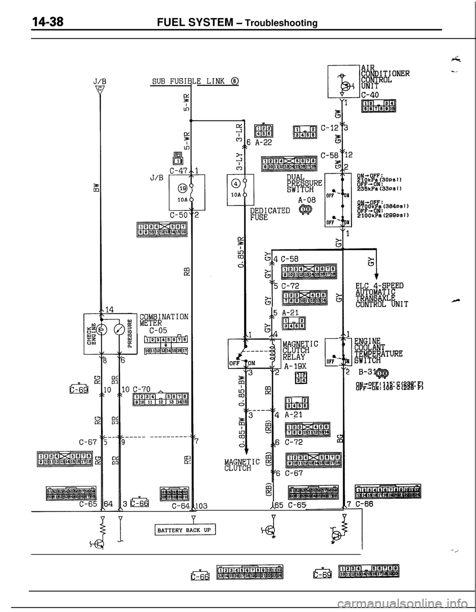
14-38FUEL SYSTEM - Troubleshooting
a-6
ISUB FUSII
52
IA
3
E
10
E
---5
:
COMBINATIONMETERc-05
______ -_-----_-.3
s
3&iC-64
3L
tc
E LINK @
i A-22
C-58
P
5 A-21
t‘s1 !L
pgm&1c
RELAY
\' A-19XCOF?
103A65 C-65
ELC 4-SPEEDAUTOMATICTRANSAXLECONTROL UNIT
1
1
ENGINE
Fb&&iiTUREI SWITCH
? B-31 12CQ
-/
Page 493 of 1216
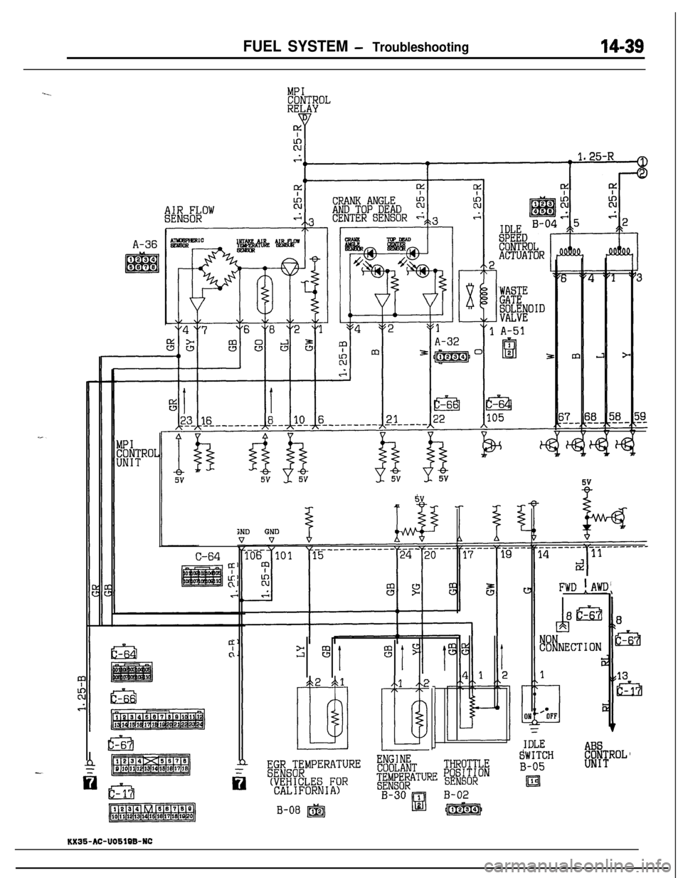
FUEL SYSTEM - Troubleshooting
A-3612IAK6 AI2AIR PLOI
MPICONTROLRELAY
C-64
4:
if
“:clp %JF3
12
”ABS-__SWITCHCONTROLTHROTTLEUNIT
c-17n
~~[GiT~MPERATURE ;;f$;$TPOSITIONB-05
(VEHICLES FOR~i#$j~TuRE SENSOR!aCALIFORNIA)B-30 1
Id
B-02
pj%imzqB-08 @JJ(m\
E3J-65v
FWD !AWD
KX35-AC-UOSlBB-NC
Page 515 of 1216
FUEL SYSTEM - MPI System Inspection <1.8L Engine>
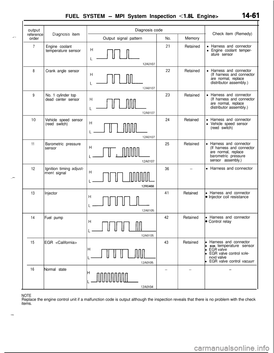
outputDiagnosis code
referenceDiagnosis itemCheck item (Remedy)
orderOutput signal patternNo.Memory
7Engine coolantRetainedl Harness and connectortemperature sensor
:-rlrLn- 2’
l Engine coolant temper-
ature sensor
12A0107
8Crank angle sensor
:nn 22
Retainedl Harness and connector
(If harness and connector
are normal, replacedistributor assembly.)
12A0107
9No. 1 cylinder top
dead center sensorH
Lnn 23
Retainedl Harness and connector
(If harness and connector
are normal, replacedistributor assembly.)
12A0107
10Vehicle speed sensor24Retainedl Harness and connector
(reed switch)H
Lu 1 nnJln
l Vehicle speed sensor
(reed switch)
12A0107
11Barometric pressure25Retainedl Harness and connector
sensorH
u I nl-uvln
(If harness and connector
are normal, replace
Lbarometric pressure
12A0107sensor assembly.)
12Ignition timing adjust-36-l Harness and connectorment signalH
LUUI nluvuuL
12R0468
13Injector
:m 41
Retainedl Harness and connector0 Injector coil resistance
12A0105
14Fuel pump42Retainedl Harness and connectorH0 Control relay
LUUUI nn
12A0105
15EGR 43Retainedl Harness and connectorl EGR temperature sensor
H
u u u u-inn
l EGRvalvel EGR valve control sole-Lnoid valve
12A0105l EGR valve control vacuurr
16Normal state---H
Ln
12A0104
NOTEReplace the engine control unit if a malfunction code is output although the inspection reveals that there is no problem with the check
items.
Page 520 of 1216
14-66FUEL SYSTEM -MPI System Inspection 4.8L Engine>
6FU1253
-1 Batterv
I6FUO751
03AOO50
03AOO57(3) Connect
6V DC between terminal @ and terminal @ of the
idle speed control servo connector, and check to be sure
that the idle speed control servo operates.
CautionApply only a 6V DC or lower voltage. Application of
higher voltage could cause locking of the servo gears.
(4)
If not, replace idle speed control servo as an assembly.
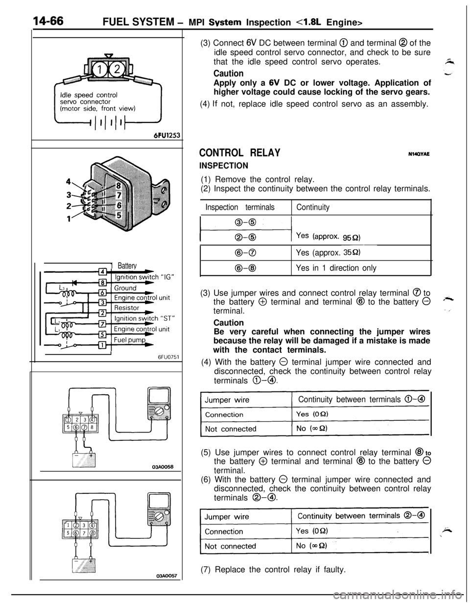
CONTROL RELAY
INSPECTION
NWWAE(1) Remove the control relay.
(2) Inspect the continuity between the control relay terminals.
Inspection terminalsContinuity
l---$+-l Yes (approx. 9552)
B-0
@-@
~~~
Yes (approx. 35Q)
Yes in 1 direction only(3) Use jumper wires and connect control relay terminal
@ to
the battery
@ terminal and terminal @ to the battery @
terminal.Caution
Be very careful when connecting the jumper wires
because the relay will be damaged if a mistake is made
with the contact terminals.
(4) With the battery
0 terminal jumper wire connected and
disconnected, check the continuity between control relay
terminals @-@I.
Continuity between terminals 0-B(5) Use jumper wires to connect control relay terminal
@I to
the battery
@ terminal and terminal @ to the battery 0
terminal.(6) With the battery
0 terminal jumper wire connected and
disconnected, check the continuity between control relay
terminals @-@I.
Continuity between terminals 0-a
1(7) Replace the control relay if faulty.
Page 521 of 1216
FUEL SYSTEM - MPI System Inspection <1.8L Engine>
POWER TRANSISTOR
Refer to GROUP 8
- Ignition System
14-67
NlQRCGAAIR CONDITIONER POWER RELAY
Refer to GROUP 24
- Air Conditioner.
N14RCLBPURGE CONTROL SOLENOID VALVE
N14RCKARefer to GROUP 25
- Evaporative Emission Control System.
EGR CONTROL SOLENOID VALVE
N14RCLARefer to GROUP 25
- Exhaust Gas Recirculation System.
