air condition MITSUBISHI ECLIPSE 1991 Workshop Manual
[x] Cancel search | Manufacturer: MITSUBISHI, Model Year: 1991, Model line: ECLIPSE, Model: MITSUBISHI ECLIPSE 1991Pages: 1216, PDF Size: 67.42 MB
Page 508 of 1216
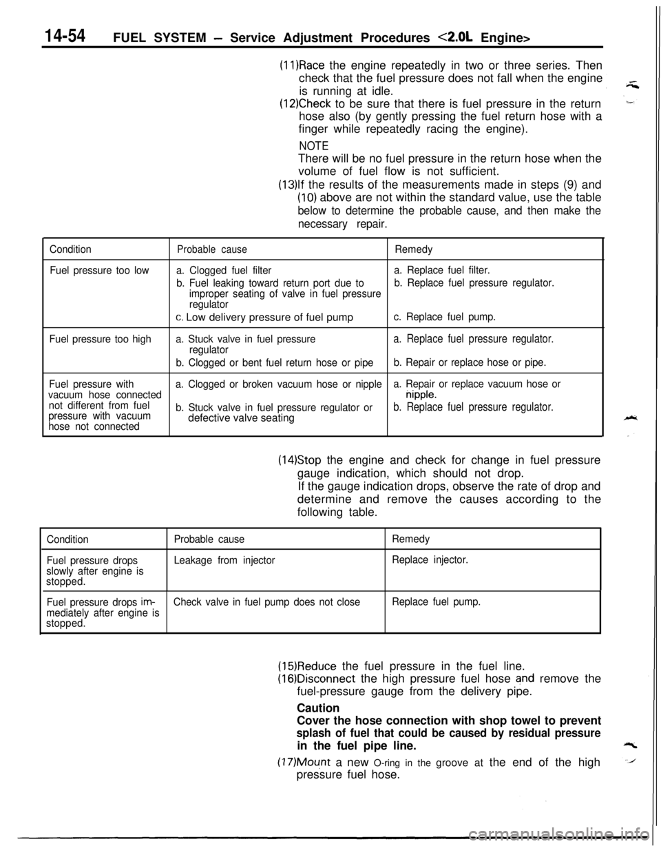
14-54FUEL SYSTEM - Service Adjustment Procedures <2.0L Engine>
(11)Race the engine repeatedly in two or three series. Then
check that the fuel pressure does not fall when the engine
is running at idle.
(12)Check to be sure that there is fuel pressure in the return
hose also (by gently pressing the fuel return hose with a
finger while repeatedly racing the engine).
NOTEThere will be no fuel pressure in the return hose when the
volume of fuel flow is not sufficient.
(13)lf the results of the measurements made in steps (9) and
(10) above are not within the standard value, use the table
below to determine the probable cause, and then make the
necessary repair.
Condition
Fuel pressure too lowProbable causeRemedy
a. Clogged fuel filtera. Replace fuel filter.
b. Fuel leaking toward return port due tob. Replace fuel pressure regulator.
improper seating of valve in fuel pressure
regulator
c. Low delivery pressure of fuel pumpc. Replace fuel pump.
Fuel pressure too higha. Stuck valve in fuel pressure
a. Replace fuel pressure regulator.regulator
b. Clogged or bent fuel return hose or pipeb. Repair or replace hose or pipe.
Fuel pressure witha. Clogged or broken vacuum hose or nipplea. Repair or replace vacuum hose or
vacuum hose connected
nipple.
not different from fuel
pressure with vacuumb. Stuck valve in fuel pressure regulator or
b. Replace fuel pressure regulator.
hose not connecteddefective valve seating
(14)Stop the engine and check for change in fuel pressure
gauge indication, which should not drop.
If the gauge indication drops, observe the rate of drop and
determine and remove the causes according to the
following table.
Condition
Fuel pressure drops
slowly after engine is
stopped.Probable cause
Leakage from injectorRemedy
Replace injector.
Fuel pressure drops
im-Check valve in fuel pump does not closeReplace fuel pump.
mediately after engine is
stopped.
(15)Reduce the fuel pressure in the fuel line.
(16)Disconnect the high pressure fuel hose and remove the
fuel-pressure gauge from the delivery pipe.
Caution
Cover the hose connection with shop towel to prevent
splash of fuel that could be caused by residual pressurein the fuel pipe line.
(17)Mount a new O-ring in the groove at the end of the high
pressure fuel hose.
Page 509 of 1216
FUEL SYSTEM - Service Adjustment Procedures <2.0L Engine>14-55
(18)Connect the high-pressure fuel hose,,to the delivery pipe
and tighten the screws to the specified torque.
(19)Check for fuel leaks.
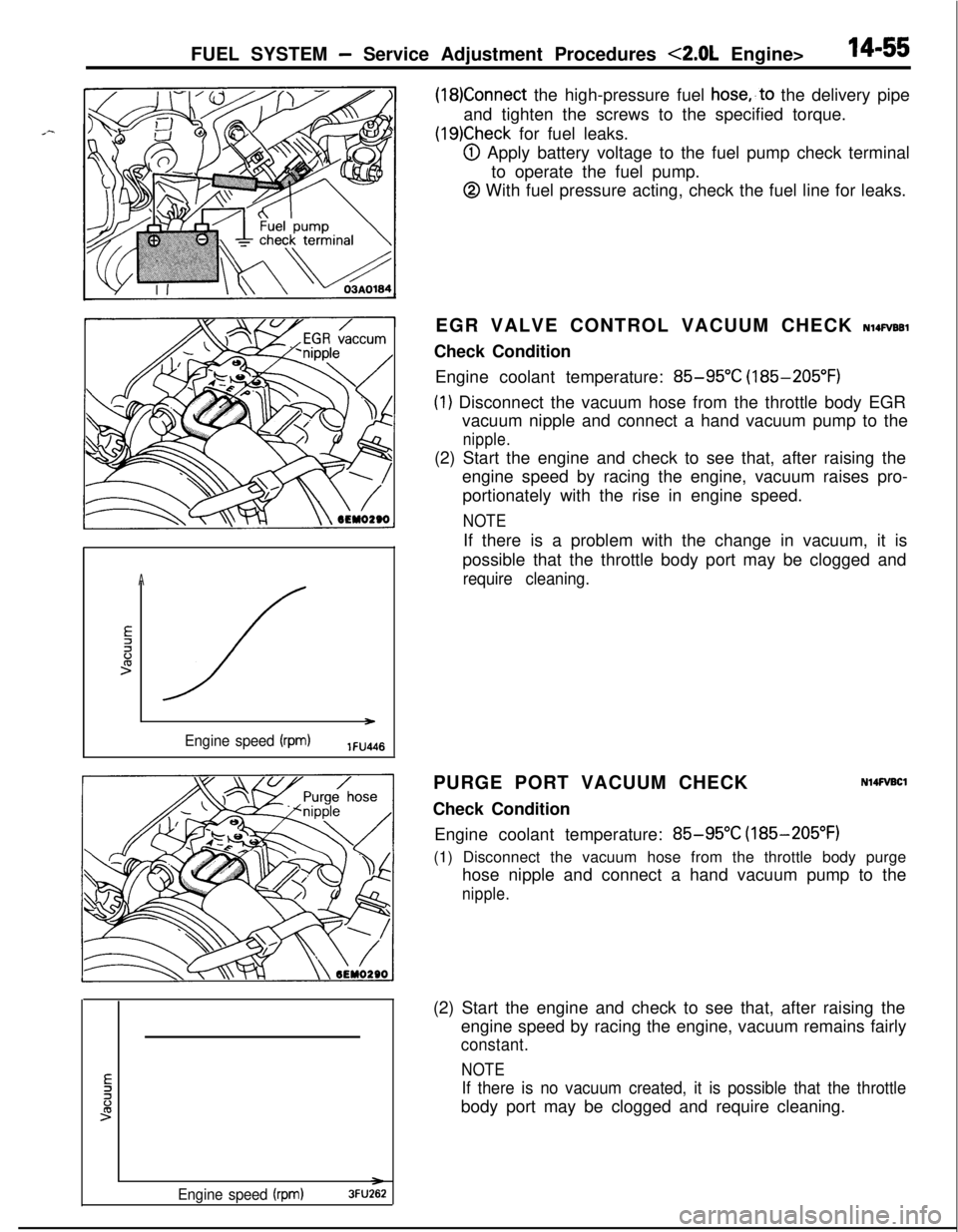
@I Apply battery voltage to the fuel pump check terminal
to operate the fuel pump.
@ With fuel pressure acting, check the fuel line for leaks.
A
E2li:>
/ )
Engine speed (rpm)lFU4l6EGR VALVE CONTROL VACUUM CHECK
NlQFVBBlCheck Condition
Engine coolant temperature:
85-95°C (185-205°F)
(1) Disconnect the vacuum hose from the throttle body EGR
vacuum nipple and connect a hand vacuum pump to the
nipple.(2) Start the engine and check to see that, after raising the
engine speed by racing the engine, vacuum raises pro-
portionately with the rise in engine speed.
NOTEIf there is a problem with the change in vacuum, it is
possible that the throttle body port may be clogged and
require cleaning.PURGE PORT VACUUM CHECK
Check Condition
N14FVBClEngine coolant temperature:
85-95°C (185-205°F)
(1) Disconnect the vacuum hose from the throttle body purge
hose nipple and connect a hand vacuum pump to the
nipple.
Engine speed (rpm)3FU262(2) Start the engine and check to see that, after raising the
engine speed by racing the engine, vacuum remains fairly
constant.
NOTE
If there is no vacuum created, it is possible that the throttlebody port may be clogged and require cleaning.
Page 512 of 1216
14-58FUEL SYSTEM -MPI System Inspection <1.8L Engine>
MALFUNCTION INDICATOR LIGHTNWQAB
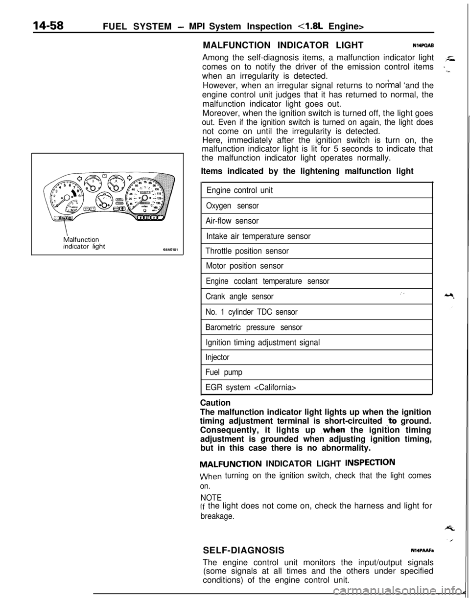
Among the self-diagnosis items, a malfunction indicator light
comes on to notify the driver of the emission control items
when an irregularity is detected.
However, when an irregular signal returns to
notmal ‘and the
engine control unit judges that it has returned to normal, the
malfunction indicator light goes out.
Moreover, when the ignition switch is turned off, the light goes
out. Even if the ignition switch is turned on again, the light doesnot come on until the irregularity is detected.
Here, immediately after the ignition switch is turn on, the
malfunction indicator light is lit for 5 seconds to indicate that
the malfunction indicator light operates normally.
Items indicated by the lightening malfunction light
Engine control unit
Oxygen sensor
Air-flow sensor
Intake air temperature sensor
Throttle position sensor
Motor position sensor
Engine coolant temperature sensor
Crank angle sensor
No. 1 cylinder TDC sensor
Barometric pressure sensor
Ignition timing adjustment signal
Injector
Fuel pump
EGR system
The malfunction indicator light lights up when the ignition
timing adjustment terminal is short-circuited
,‘t’o ground.
Consequently, it lights up ,when the ignition timing
adjustment is grounded when adjusting ignition timing,
but in this case there is no abnormality.
MALFUNCTION INDICATOR LIGHT INSPECTlON
When turning on the ignition switch, check that the light comes
on.
NOTElf the light does not come on, check the harness and light for
breakage.SELF-DIAGNOSIS
Nl4PMFaThe engine control unit monitors the input/output signals
(some signals at all times and the others under specified
conditions) of the engine control unit.
Page 514 of 1216
14-60FUEL SYSTEM - MPI Svstem lnwection <1.8L Engine>
7 MPI
diagnosis
LGround
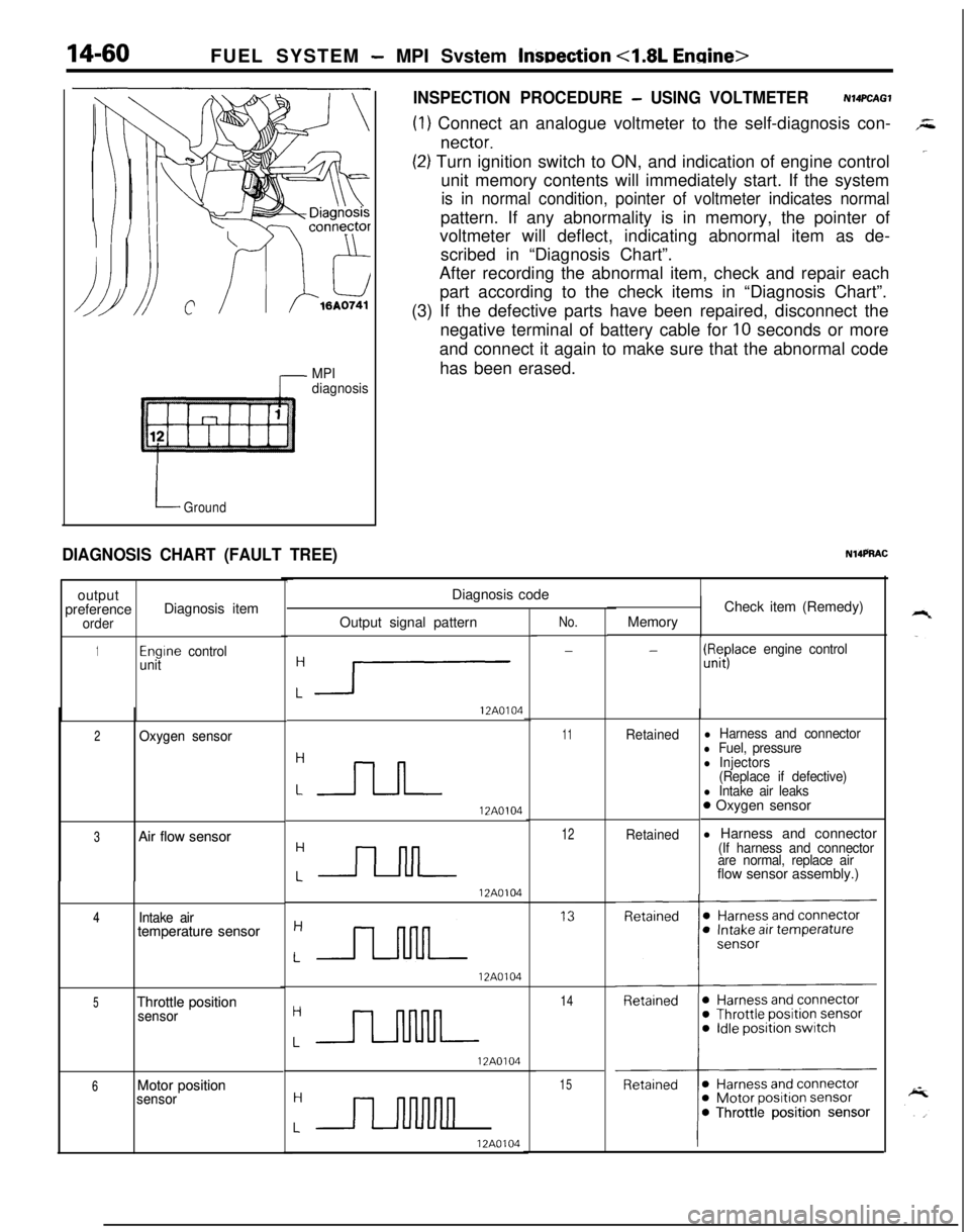
DIAGNOSIS CHART (FAULT TREE)output
preference
orderDiagnosis item
1Engrne control
unit
2 2Oxygen sensor Oxygen sensor
3 3Air flow sensor Air flow sensor
4 4Intake air Intake airtemperature sensor temperature sensor
5 5Throttle position Throttle positionsensor sensor
6 6Motor position Motor positionsensor sensor
INSPECTION PROCEDURE - USING VOLTMETERN14PCAGl
(1) Connect an analogue voltmeter to the self-diagnosis con-,z
nectar.
‘~(2) Turn ignition switch to ON, and indication of engine control
unit memory contents will immediately start. If the system
is in normal condition, pointer of voltmeter indicates normalpattern. If any abnormality is in memory, the pointer of
voltmeter will deflect, indicating abnormal item as de-
scribed in “Diagnosis Chart”.
After recording the abnormal item, check and repair each
part according to the check items in “Diagnosis Chart”.
(3) If the defective parts have been repaired, disconnect the
negative terminal of battery cable for
10 seconds or more
and connect it again to make sure that the abnormal code
has been erased.
N14PRACDiagnosis code
Output signal pattern
:1
12A0104
12A0104
12A0104
12A0104
:JJlJJ--
12A0104
LII
12A0104
No.
-
11Retained
12Retained
14
15MemoryCheck item (Remedy)
-(ll#ace engine control
l Harness and connectorl Fuel, pressurel Injectors
(Replace if defective)
l Intake air leaks0 Oxygen sensor
l Harness and connector
(If harness and connector
are normal, replace airflow sensor assembly.)
Page 518 of 1216
14-64FUEL SYSTEM -MPI System Inspection <1.8L Engine>
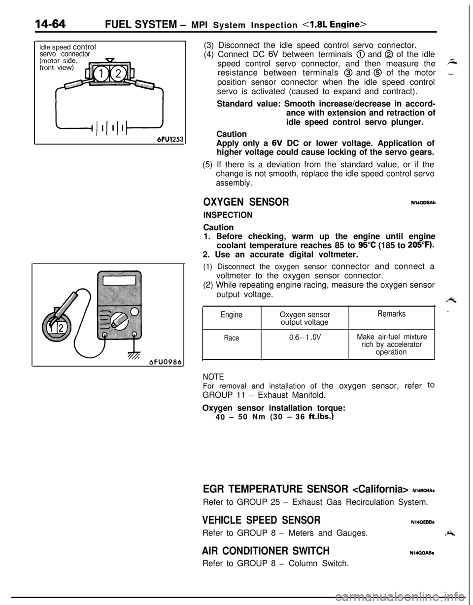
Idle speed controlservo connector
6FU098t(3) Disconnect the idle speed control servo connector.
(4) Connect DC
6V between terminals @) and @ of the idle
speed control servo connector, and then measure the
resistance between terminals
@ and @ of the motor
position sensor connector when the idle speed control
servo is activated (caused to expand and contract).
Standard value: Smooth increase/decrease in accord-
ance with extension and retraction of
idle speed control servo plunger.
Caution
Apply only a 6V DC or lower voltage. Application of
higher voltage could cause locking of the servo gears.
(5) If there is a deviation from the standard value, or if the
change is not smooth, replace the idle speed control servo
assembly.
OXYGEN SENSORN14QDBAb
INSPECTIONCaution
1. Before checking, warm up the engine until engine
coolant temperature reaches 85 to
95°C (185 to 205°F).2. Use an accurate digital voltmeter.
(1) Disconnect the oxygen sensor connector and connect a
voltmeter to the oxygen sensor connector.
(2) While repeating engine racing, measure the oxygen sensor
output voltage.
EngineOxygen sensor
output voltageRemarks
Race0.6- 1 .OVMake air-fuel mixture
rich by accelerator
operation
NOTEFor removal and installation of the oxygen sensor, refer
toGROUP 11
- Exhaust Manifold.
Oxygen sensor installation torque:
40
-50 Nm (30 - 36 klbs.)
EGR TEMPERATURE SENSOR
- Exhaust Gas Recirculation System.
VEHICLE SPEED SENSORN14QEEBaRefer to GROUP 8
- Meters and Gauges.
AIR CONDITIONER SWITCHRefer to GROUP 8
- Column Switch.
N14QQABa
Page 521 of 1216

FUEL SYSTEM - MPI System Inspection <1.8L Engine>
POWER TRANSISTOR
Refer to GROUP 8
- Ignition System
14-67
NlQRCGAAIR CONDITIONER POWER RELAY
Refer to GROUP 24
- Air Conditioner.
N14RCLBPURGE CONTROL SOLENOID VALVE
N14RCKARefer to GROUP 25
- Evaporative Emission Control System.
EGR CONTROL SOLENOID VALVE
N14RCLARefer to GROUP 25
- Exhaust Gas Recirculation System.
Page 528 of 1216
FUEL SYSTEM- MPI Svstem InsDection <2.0L DOHC Engine>
MPI
diagnosis
I Ground
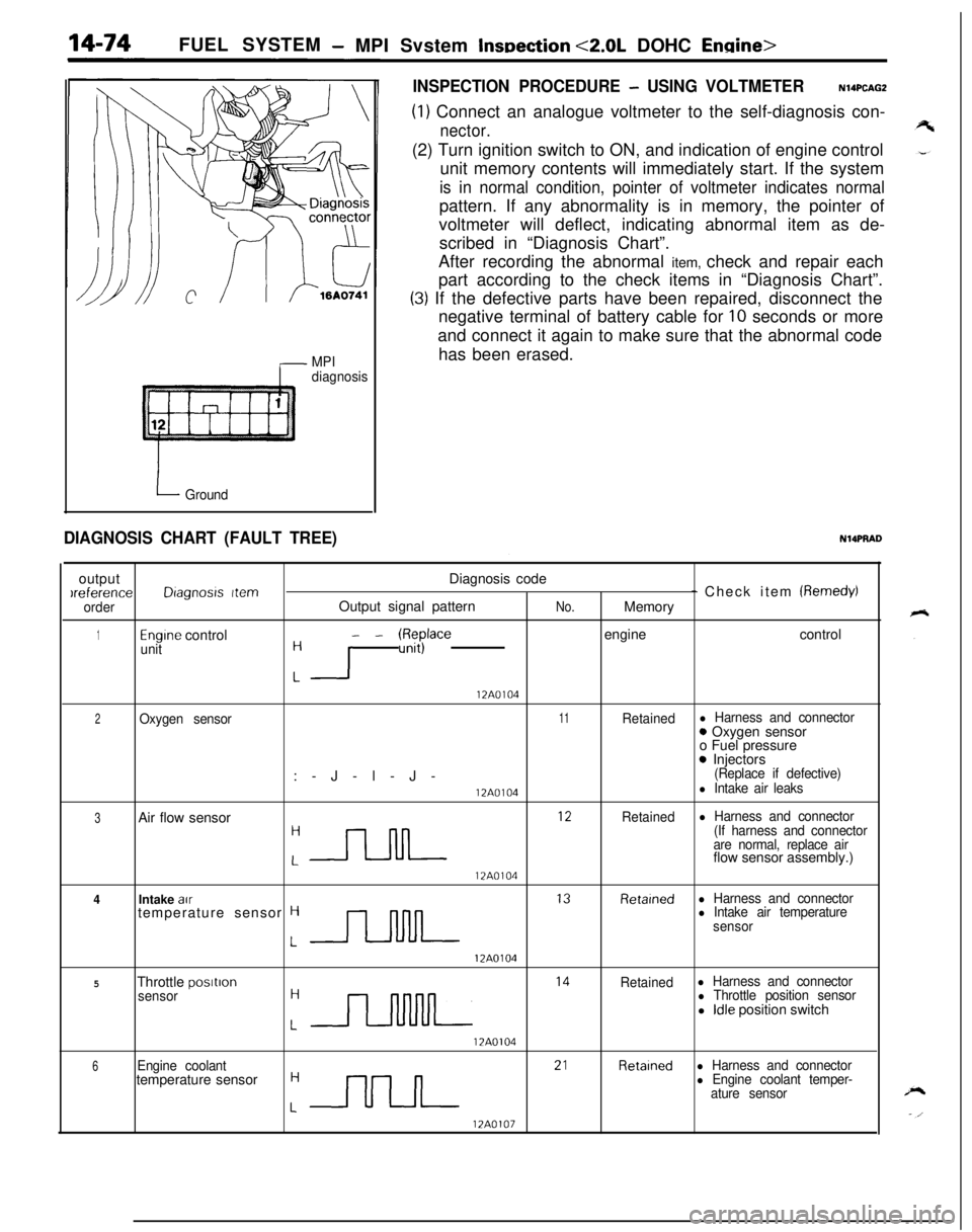
INSPECTION PROCEDURE - USING VOLTMETERN14PCAGZ
(1) Connect an analogue voltmeter to the self-diagnosis con-
nector.(2) Turn ignition switch to ON, and indication of engine control
unit memory contents will immediately start. If the system
is in normal condition, pointer of voltmeter indicates normalpattern. If any abnormality is in memory, the pointer of
voltmeter will deflect, indicating abnormal item as de-
scribed in “Diagnosis Chart”.
After recording the abnormal item, check and repair each
part according to the check items in “Diagnosis Chart”.
(3) If the defective parts have been repaired, disconnect the
negative terminal of battery cable for
10 seconds or more
and connect it again to make sure that the abnormal code
has been erased.
DIAGNOSIS CHART (FAULT TREE)NlQPRADoutputDiagnosis codeIreference
Dragnosrs Item- Check item (Remedy)
orderOutput signal patternNo.Memory
1Engine controlunit- - W$$ace engine control: I
12A0104
2Oxygen sensor11Retainedl Harness and connector:-J-l-J-0 Oxygen sensor
o Fuel pressure
0 Injectors(Replace if defective)
12A0104l Intake air leaks
3Air flow sensor
:-rLJL ‘*
Retainedl Harness and connector
(If harness and connector
are normal, replace airflow sensor assembly.)
12A0104
4Intake au
J--lNlL l3
Retarnedl Harness and connectortemperature sensor Hl Intake air temperature
sensor
12A0104
5Throttle postron
:n l4
Retainedl Harness and connector
sensorl Throttle position sensorl Idle position switch
17A0104
6Engine coolant
:nn 2’
Retainedl Harness and connectortemperature sensorl Engine coolant temper-
ature sensor
12A0107
Page 533 of 1216
FUEL SYSTEM - MPI System Inspection <2.0L QOHC Engine>14-79EGR TEMPERATURE SENSOR
N14RCHAaRefer to GROUP 25
- Exhaust Gas Recirculation System.
VEHICLE SPEED SENSOR
Refer to GROUP 8
- Meters and Gauges.
N140EBBaAIR CONDITIONER SWITCH
Nl4QQAEaRefer to GROUP 8
- Column Switch.
POWER STEERING OIL PRESSURE SWITCH
N14RCJBRefer to GROUP 19 for power steering system inspection.
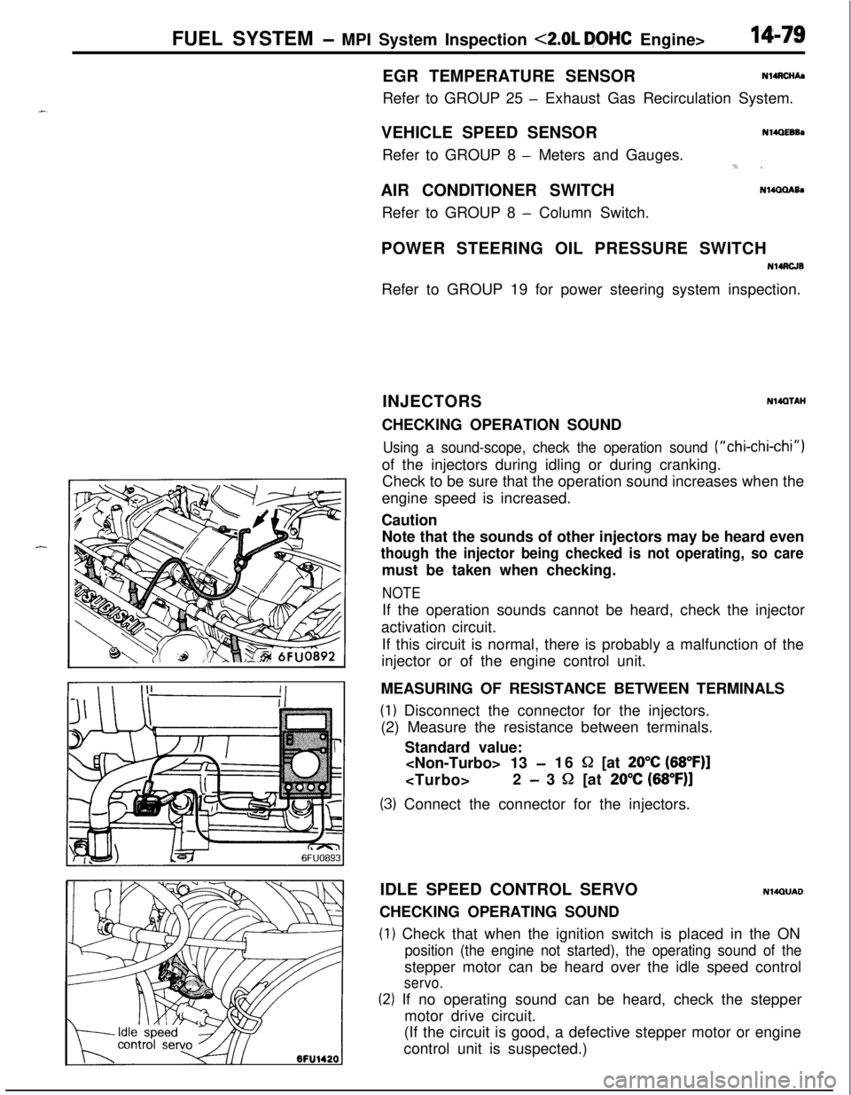
INJECTORS
NWXAHCHECKING OPERATION SOUND
Using a sound-scope, check the operation sound (“chi-chi-chi”)of the injectors during idling or during cranking.
Check to be sure that the operation sound increases when the
engine speed is increased.
Caution
Note that the sounds of other injectors may be heard even
though the injector being checked is not operating, so caremust be taken when checking.
NOTEIf the operation sounds cannot be heard, check the injector
activation circuit.
If this circuit is normal, there is probably a malfunction of the
injector or of the engine control unit.
MEASURING OF RESISTANCE BETWEEN TERMINALS
(1) Disconnect the connector for the injectors.
(2) Measure the resistance between terminals.
Standard value:
-16 S2 [at 20°C (68”F)]
- 3 52 [at 20% (68”F)]
(3) Connect the connector for the injectors.
IDLE SPEED CONTROL SERVO
N14QUADCHECKING OPERATING SOUND
(1) Check that when the ignition switch is placed in the ON
position (the engine not started), the operating sound of thestepper motor can be heard over the idle speed control
servo.
(2) If no operating sound can be heard, check the stepper
motor drive circuit.
(If the circuit is good, a defective stepper motor or engine
control unit is suspected.)
Page 536 of 1216
14-82FUEL SYSTEM - MPI System Inspection <2.0L DOHC Engine>
\ \\I \3FUO352
,\ \
\I \3FUO353
,\ ‘\R/
\ \\I \3FUo354
POWER TRANSISTORRefer to GROUP 8
- Ignition System
NlIAcQAl
a-4
AIR CONDITIONER POWER RELAYN14NCl.a -Refer to GROUP 24
- Air Conditioner.
PURGE CONTROL SOLENOID VALVEN14RCKARefer to GROUP 25
- Evaporative Emission Control System.
EGR CONTROL SOLENOID VALVE
N14NCURefer to GROUP 25
- Exhaust Gas Recirculation System.
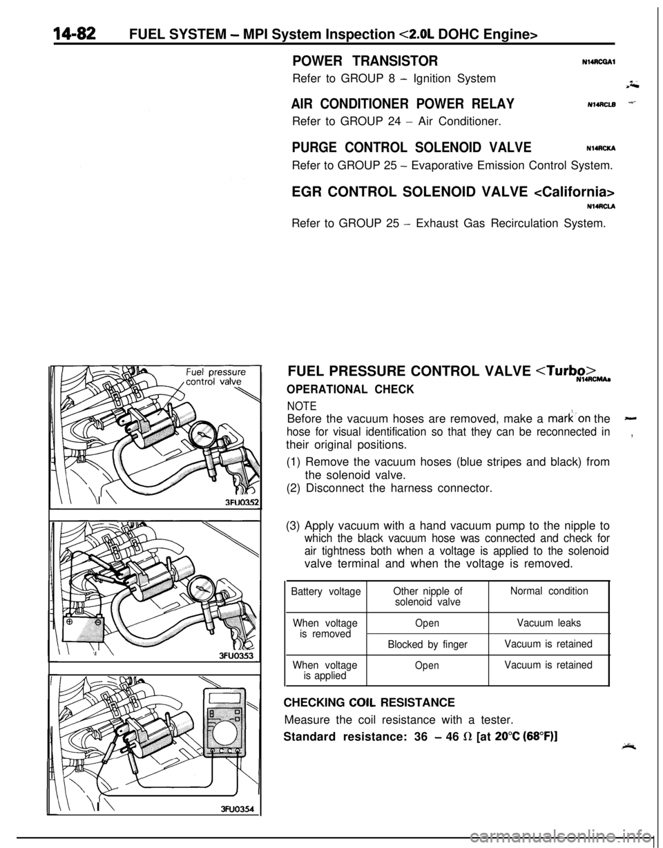
FUEL PRESSURE CONTROL VALVE
NOTEBefore the vacuum hoses are removed, make a mark’on the
-
hose for visual identification so that they can be reconnected in,their original positions.
(1) Remove the vacuum hoses (blue stripes and black) from
the solenoid valve.
(2) Disconnect the harness connector.
(3) Apply vacuum with a hand vacuum pump to the nipple to
which the black vacuum hose was connected and check for
air tightness both when a voltage is applied to the solenoidvalve terminal and when the voltage is removed.
Battery voltageOther nipple of
solenoid valveNormal condition
When voltage
is removed
When voltage
is applied
OpenVacuum leaks
Blocked by fingerVacuum is retained
OpenVacuum is retainedCHECKING
COIL RESISTANCE
Measure the coil resistance with a tester.
Standard resistance: 36
- 46 R [at 20°C (68”F)]
Page 560 of 1216
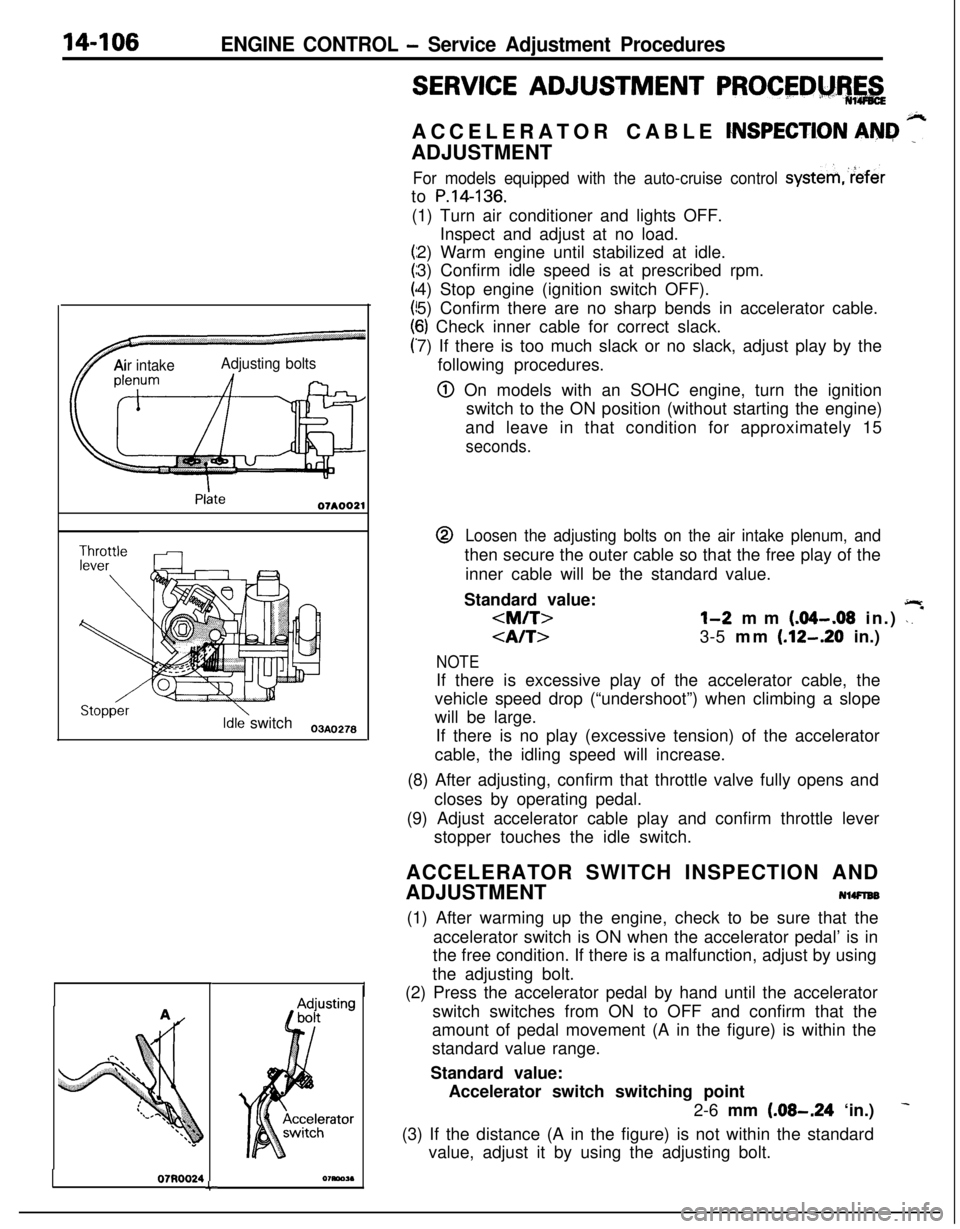
14-106ENGINE CONTROL - Service Adjustment Procedures
TAir intakeAdjusting bolts
Idle switch03A,,2.8
07RQ024L
I
SERVICE ADJUSTMENT PROCEDM%,&ACCELERATOR CABLE
CNSPECTION AN&I ”ADJUSTMENT
For models equipped with the auto-cruise control systemreferto
P.14-136.(1) Turn air conditioner and lights OFF.
Inspect and adjust at no load.
2) Warm engine until stabilized at idle.
3) Confirm idle speed is at prescribed rpm.
4) Stop engine (ignition switch OFF).
5) Confirm there are no sharp bends in accelerator cable.
6) Check inner cable for correct slack.
7) If there is too much slack or no slack, adjust play by the
following procedures.
@ On models with an SOHC engine, turn the ignition
switch to the ON position (without starting the engine)
and leave in that condition for approximately 15
seconds.@
Loosen the adjusting bolts on the air intake plenum, andthen secure the outer cable so that the free play of the
inner cable will be the standard value.
Standard value:
jlr
3-5 mm (.12-.20 in.)
NOTEIf there is excessive play of the accelerator cable, the
vehicle speed drop (“undershoot”) when climbing a slope
will be large.
If there is no play (excessive tension) of the accelerator
cable, the idling speed will increase.
(8) After adjusting, confirm that throttle valve fully opens and
closes by operating pedal.
(9) Adjust accelerator cable play and confirm throttle lever
stopper touches the idle switch.
ACCELERATOR SWITCH INSPECTION AND
ADJUSTMENT
NlWlEB(1) After warming up the engine, check to be sure that the
accelerator switch is ON when the accelerator pedal’ is in
the free condition. If there is a malfunction, adjust by using
the adjusting bolt.
(2) Press the accelerator pedal by hand until the accelerator
switch switches from ON to OFF and confirm that the
amount of pedal movement (A in the figure) is within the
standard value range.
Standard value:
Accelerator switch switching point
2-6 mm
(.08-.24 ‘in.)
(3) If the distance (A in the figure) is not within the standard
value, adjust it by using the adjusting bolt.