air condition MITSUBISHI ECLIPSE 1991 Workshop Manual
[x] Cancel search | Manufacturer: MITSUBISHI, Model Year: 1991, Model line: ECLIPSE, Model: MITSUBISHI ECLIPSE 1991Pages: 1216, PDF Size: 67.42 MB
Page 455 of 1216
14-IFUEL SYSTEM
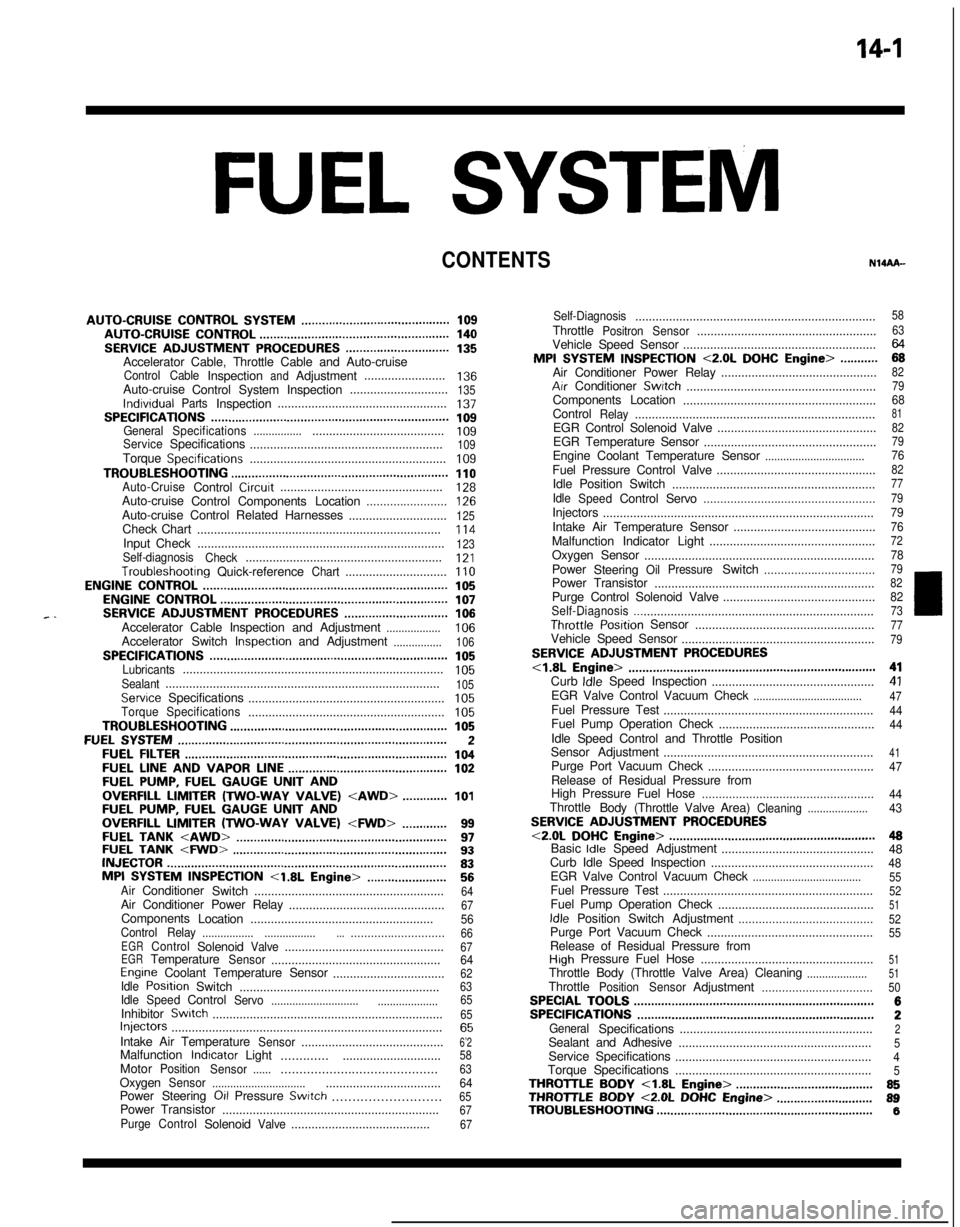
CONTENTS
AUTO-CRUISECONTROLSYSTEM...........................................109AUTO-CRUISECONTROL.......................................................140SERVICEADJUSTMENTPROCEDURES..............................135Accelerator Cable, Throttle Cable and Auto-cruise
ControlCableInspectionandAdjustment........................136Auto-cruise
ControlSystemInspection.............................135lndrvrdualPartsInspection..................................................137SPECIFICATIONS.....................................................................109GeneralSpecifications.......................................................109ServiceSpecifications
.........................................................109Torque Specrfications..........................................................109TROUBLESHOOTING...............................................................110Auto-CruiseControlCircurt................................................128Auto-cruise
ControlComponentsLocation........................126Auto-cruise Control Related Harnesses
.............................125Check Chart
........................................................................114Input Check.........................................................................123Self-diagnosis
Check..........................................................121Troubleshootrng
Quick-referenceChart..............................110ENGINECONTROL.......................................................................105ENGINECONTROL..................................................................107--SERVICEADJUSTMENTPROCEDURES..............................106Accelerator Cable Inspection and Adjustment..................106Accelerator Switch Inspectron and Adjustment................106SPECIFICATIONS.....................................................................105Lubricants.............................................................................105Sealant.................................................................................105ServiceSpecifications
..........................................................105TorqueSpecifications..........................................................105TROUBLESHOOTING...............................................................105FUELSYSTEM..............................................................................2FUELFILTER............................................................................104FUELLINEANDVAPORLINE..............................................102FUEL PUMP, FUEL GAUGE UNIT ANDOVERFILL LIMITER(TWO-WAY VALVE)
Switch........................................................64Air Conditioner Power Relay
..............................................67Components
Location......................................................56
ControlRelay
.................................................................66EGRControlSolenoidValve...............................................67EGRTemperatureSensor..................................................64Engine Coolant Temperature Sensor
.................................62IdlePosrtionSwitch
...........................................................63IdleSpeedControlServo
.............................
....................65InhibitorSwitch....................................................................65hjeCtOrS................................................................................65IntakeAirTemperatureSensor..........................................6’2MalfunctionlndtcatorLight
..........................................58MotorPosition
Sensor................................................63OxygenSensor
.................................................................64Power Steering 011 Pressure Swatch...........................65PowerTransistor
................................................................67PurgeControlSolenoidValve.........................................67
Self-Diagnosis.......................................................................
ThrottlePositronSensor.....................................................
Vehicle Speed Sensor.........................................................MPI
SYSTEMINSPECTION<2.0L DOHCEngine>...........Air Conditioner Power Relay..............................................
Arr Conditioner Swatch........................................................
Components Location
.........................................................
Control
Relay.......................................................................
EGR Control Solenoid Valve...............................................
EGR Temperature Sensor
...................................................
Engine Coolant Temperature Sensor
.................................Fuel Pressure Control Valve...............................................
Idle Position Switch
............................................................
Idle
SpeedControlServo...................................................Injectors
................................................................................
Intake Air Temperature Sensor..........................................
Malfunction Indicator Light.................................................
Oxygen Sensor
....................................................................
Power
Steering
OilPressureSwitch.................................Power Transistor
.................................................................
Purge Control Solenoid Valve.............................................
Self-Diaanosis.......................................................................
58
63
2382
79
688182
79
7682
77
79
79
76
727879
82
8273ThrottletiPosition Sensor
.....................................................77Vehicle Speed Sensor
.........................................................79SERVICE ADJUSTMENT PROCEDURES<1.8L Engine>........................................................................41Curb Idle Speed Inspection
................................................41EGR Valve Control Vacuum Check....................................47Fuel Pressure Test
..............................................................44Fuel Pump Operation Check
..............................................44Idle Speed Control and Throttle Position
Sensor Adjustment
..............................................................
41Purge Port Vacuum Check
.................................................47Release of Residual Pressure from
High Pressure Fuel Hose
...................................................
44Throttle
Body(Throttle Valve Area)Cleaning....................43SERVICE ADJUSTMENT PROCEDURES<2.0LDOHCEngine>............................................................48Basic Idle Speed Adjustment
.............................................
48
Curb Idle Speed Inspection
................................................48EGR Valve Control Vacuum Check....................................55Fuel Pressure Test
..............................................................52Fuel Pump Operation Check
..............................................51Idle Position Switch Adjustment........................................52Purge Port Vacuum Check
.................................................55Release of Residual Pressure from
High Pressure Fuel Hose
...................................................51Throttle Body (Throttle Valve Area) Cleaning....................51ThrottlePositionSensorAdjustment.................................50SPECIALTOOLS......................................................................6SPECIFICATIONS.....................................................................2GeneralSpecifications.........................................................2Sealant and Adhesive
.........................................................5Service Specifications
..........................................................4Torque Specifications
..........................................................5THROlTLEBODY<1.8LEngine>........................................85THROlTLE BODY <2.0L DOHC Engine>............................89TROUBLESHOOTING...............................................................6
Page 458 of 1216
FUEL SYSTEM- Specifications
ItemsSpecifications
Fuel pressure regulator
Regulated pressurekPa (psi)
255 (36.3)
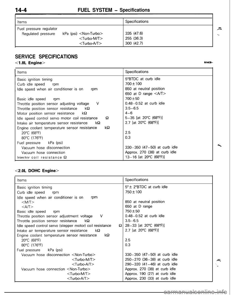
SERVICE SPECIFICATIONS
<1.8L Engine>N14CB-
ItemsSpecifications
Basic ignition timing~
Curb idle speedvm
, Idle speed when air conditioner is onrpm
Basic idle speedwm
Throttle position sensor adjusting voltageV
Throttle position sensor resistancekQMotor position
sensor resistancek&
Idle speed control servo motor coil resistance
Intake air temperature sensor resistancekQ
Engine coolant temperature sensor resistance
20°C (68°F)
80°C (176°F)
Fuel pressurekPa (psi)
Vacuum hose disconnection
Vacuum hose connection
Iniectnr coil resistance Q
52
k8
5”BTDC at curb idle
700f 100
850 at neutral position
650 at D range
700 f 50
0.48-0.52 at curb idle
3.5-6.5
4-6
5-35 [at 20°C (68”F)l
2.7 [at 20°C (68”F)I
2.5
0.3
330-350 (47-50) at curb idleApprox.
270 (38) at curb idle
13-16 [at 20°C (68”F)l
<2.0L DOHC Engine>
Items( Specifications
Basic ignition timing
Curb idle speedrpm
Idle speed when air conditioner is onrpm
al-r>
Basic idle speedrpm
Throttle position sensor adjustment voltageVThrottle position
sensor resistancekQ
Idle speed control servo (stepper motor) coil resistance
Intake air temperature sensor resistancekQ
Engine coolant temperature sensor resistancek0
20°C (68°F)
80°C (176°F)
Fuel pressurekPa (psi)
Vacuum hose disconnection
Vacuum hose connection
Q
5”+ 2”BTDC at curb idle
750+ 100
850 at neutral position
650 at D range
750 f 50
0.48-0.52 at curb idle
3.5-6.5
28-33 [at 20°C (68”F)l
2.7 [at 20°C (68”F)I
2.5
0.3
330-350 (47-50) at curb idle
250-270 (36-38) at curb idle
290-320 (41-46) at curb idleApprox.
270 (38) at curb idle
Approx. 190 (27) at curb idle
Approx. 230 (33) at curb idle
Page 461 of 1216
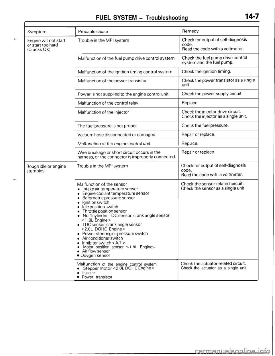
FUEL SYSTEM - Troubleshooting14-7
Symptom
Engine will not startor start too hard(Cranks OK)
Rough idle or engine
stumbles
Trouble in the MPI systemCheck for output of self-diagnosis
code.Read the code with a voltmeter.Malfunction
of the fuel pump drive control systemCheck the fuel pump drive controlsystem
and the fuel pump.Malfunction
of the ignition timing control systemMalfunction
of the power transistor
Check the ignition timing.
Check the power transistor as a single
unit.
Power is not supplied to the engine control unit.Check the power supply circuit.Malfunction
of the control relayMalfunction
of the injector
Replace.
Check the injector drive circuit.
Check the injector as a single unit.
The fuel pressure is not proper.Check the fuel pressure.
I
Vacuum hose disconnected or damagedRepair or replace.IMalfunction of
the engine control unit) Replace.
Wire breakage or short circuit occurs in theRepair or replace.
harness, or the connector is improperly connected.
Trouble in the MPI systemCheck for output of self-diagnosis
code.Read the code with a voltmeter.Malfunction
of the sensor
l Intake air temperature sensor
Check the sensor-related circuit.
Check the sensor as a single unit
Probable causeRemedy
l Engine coolant temperature sensorl Barometric pressure sensor
l Ignition switchl Idle position switchl Throttle position sensorl No. 1 cylinder TDC sensor, crank angle sensor
l TDC sensor, crank angle sensor<2.0L DOHC Engine>
l Power steering oil pressure switch
l Air conditioner switch
l Inhibitor switch l Motor position sensor <1.8L Engine>l Air flow sensor0 Oxygen sensorMalfunction of the engine control system
l
Stepper motor <2.0L DOHC Engine>l Injector0 Power transistor
Check the actuator-related circuit.Check the actuator as a single unit.
Page 462 of 1216
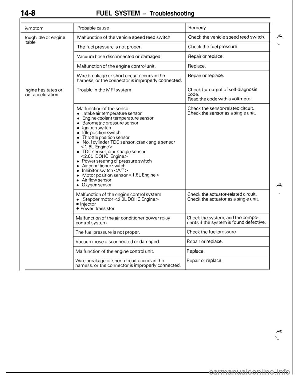
14-8FUEL SYSTEM - Troubleshootingiymptom
Probable causeMalfunction
of the vehicle speed reed switch
Remedy
Check the vehicle speed reed switch.
The fuel pressure is not proper.Check the fuel pressure.
Vacuum hose disconnected or damaged.Repair or replace.Malfunction
of the engine control unit.Replace.
Wire breakage or short circuit occurs in theRepair or replace.
harness, or the connector is improperly connected.
.ngine hesrtates oroor accelerationTrouble in the MPI systemCheck for output of self-diagnosiscode.Read the code with a voltmeter.
Malfunction of the sensorl Intake air temperature sensor
l Engine coolant temperature sensor
l Barometric pressure sensorl Ignition switch
l Idle position switchl Throttle position sensor
Check the sensor-related circuit.Check the sensor as a single unit.l
No. 1 cylinder TDC sensor, crank angle sensor
l TDC sensor, crank angle sensor<2.0L DOHC Engine>
l Power steering oil pressure switchl Air conditioner switchl Inhibitor switch l Motor position sensor
l Air flow sensor
l Oxygen sensorMalfunction
of the engine control system
l
Stepper motor <2.0L DOHC Engine>
0 Injector0 Power transistor
Check the actuator-related circuit.
Check the actuator as a single unit.Malfunction
of the air conditioner power relayCheck the system, and the compo-
control systemnents if the system is found defective.
The fuel pressure is not proper.Check the fuel pressure.
Vacuum hose disconnected or damaged.Repair or replace.Malfunction
of the engine control unit.Replace.
Wrre breakage or short circuit occurs in theRepair or replace.
harness, or the connector is improperly connected.
Page 463 of 1216
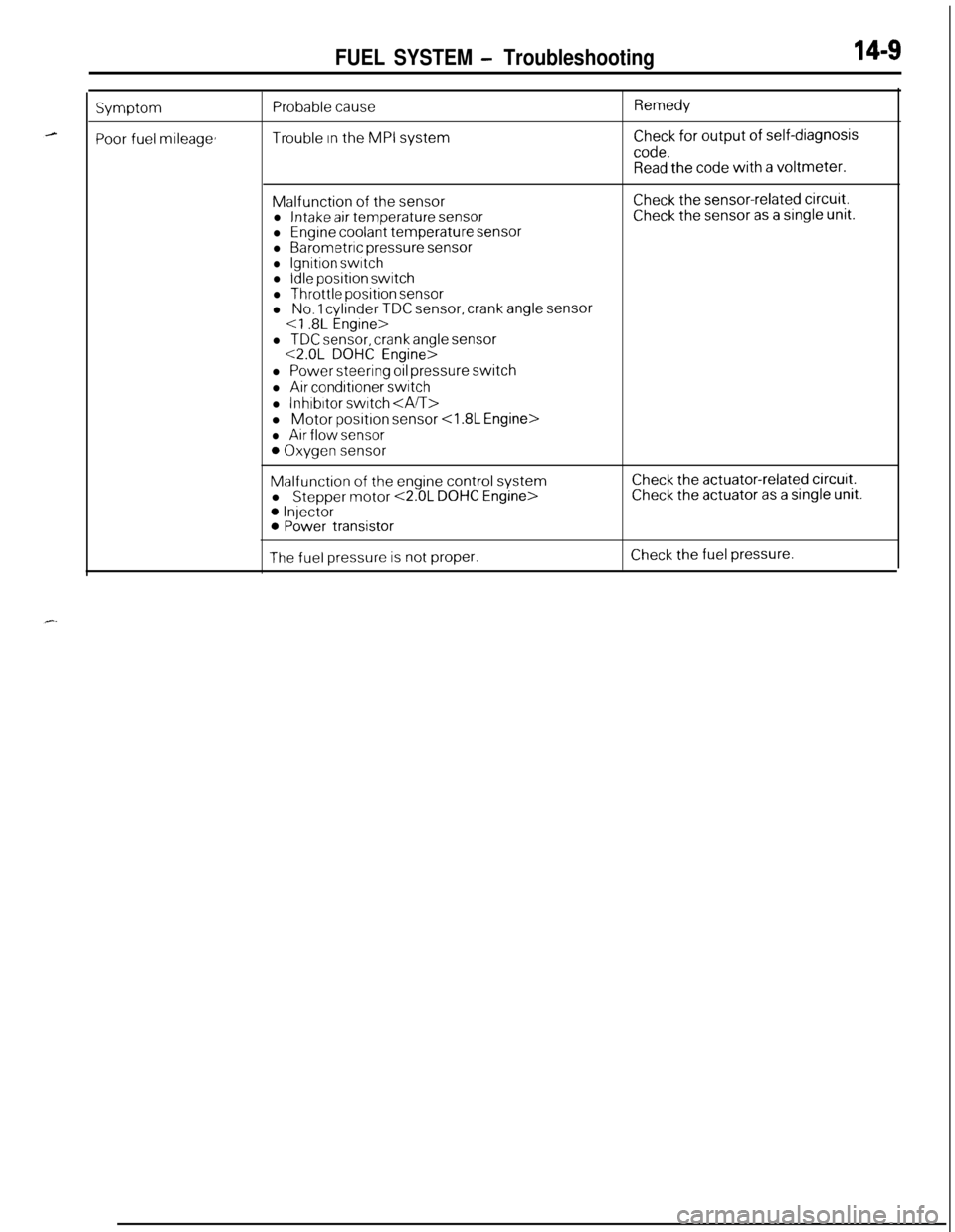
FUEL SYSTEM - Troubleshooting14-S
Symptom
Poor fuel mileage,
Probable cause
Trouble In the MPI system
Remedy
Check for output of self-diagnosis
code.Read the code with a voltmeter.Malfunction
of the sensorl Intake air temperature sensorl Engine coolant temperature sensorl Barometric pressure sensorl Ignition switchl Idle position switch
l Throttle position sensorl No. 1 cylinder TDC sensor, crank angle sensor
Check the sensor-related circuit.Check the sensor as a single unit.
l TDC sensor, crank angle sensor<2.0L DOHC Engine>
l Power steering oil pressure switch
l Air conditioner switch
l lnhrbrtor switch l Motor
position sensor
l Air flow sensor
0 Oxygen sensor
Malfunction of the engine control system
l Stepper motor <2.0L DOHC Engine>
0 Injector0 Power transistor
Check the actuator-related circurt.Check the actuator as a single unit.
The fuel pressure is not proper.Check the fuel pressure.
Page 464 of 1216
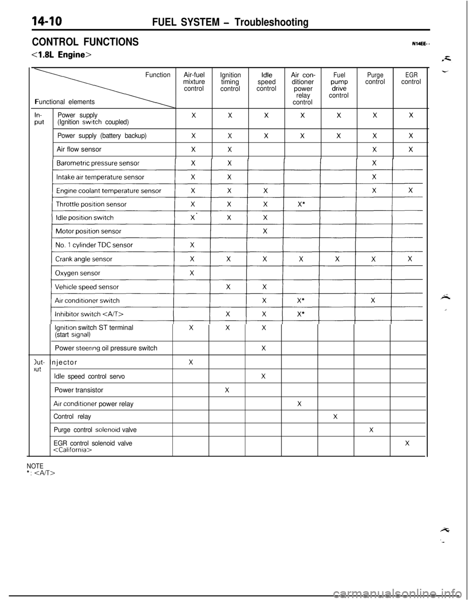
CONTROL FUNCTIONS
<1.8L Engine>
NWEEE- -
FunctionAir-fuelIgnitionIdleAir con-FuelPurgeEGRmixture
timingspeedditionercontrol
controlcontrolpower“d”,i2controlcontrol
relaycontrol
Functional elements
control
In-Power supplyXXXXXXX
Put(Ignition switch coupled)
Power supply (battery backup)
XXXXXXXAir flow sensor
XXXX
lgnitron switch ST terminalXXX(start srgnal)Power
steenng oil pressure switchX
Jut- InjectorXlutIdle speed control servoXPower transistor
X
Arr conditioner power relayX
Control relayX
Purge control solenord valveX
EGR control solenoid valveX
NOTE*:
FUEL SYSTEM - Troubleshooting
Page 465 of 1216
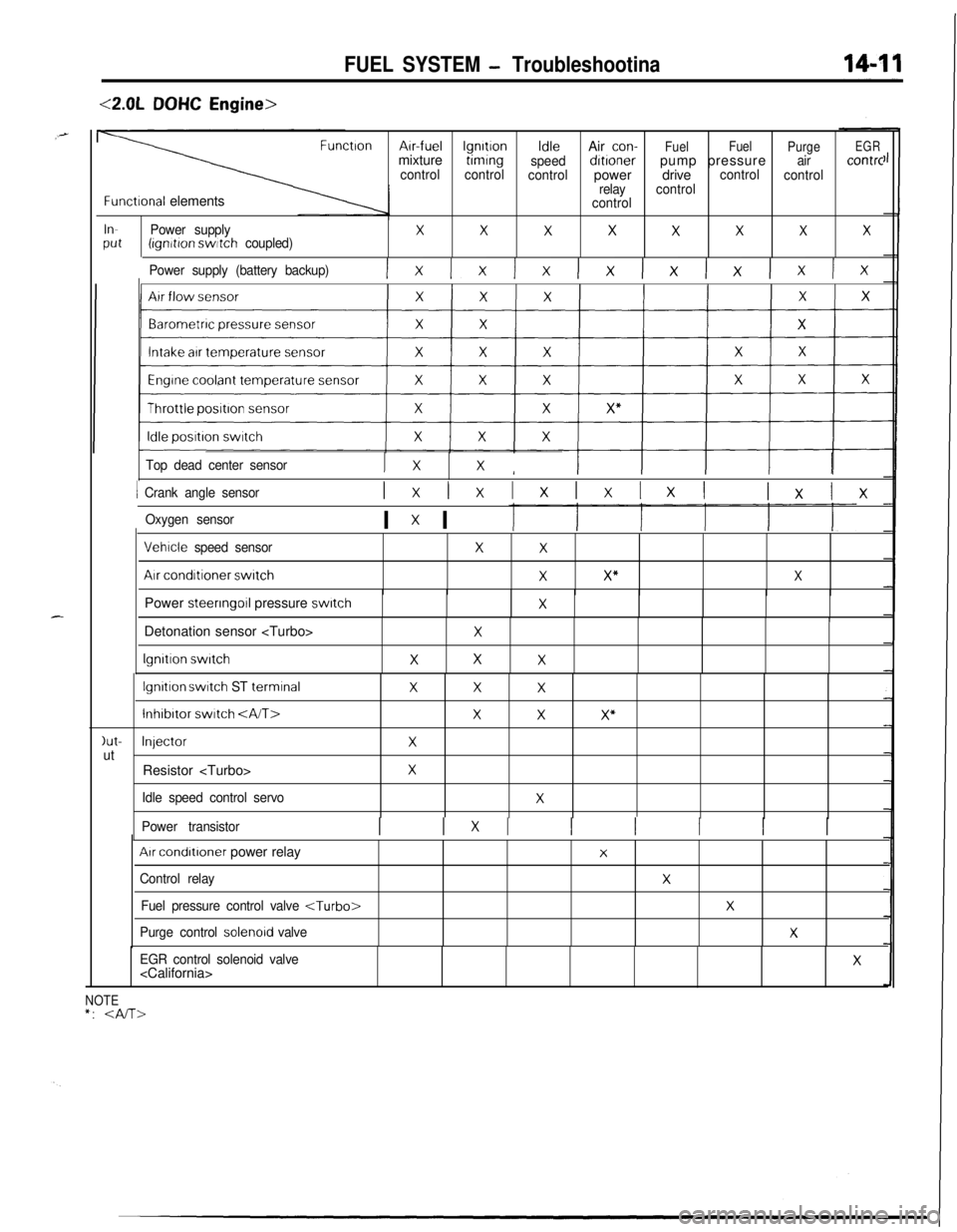
FUEL SYSTEM - Troubleshootina
<2.0LDOHC Engine>
FunctronArr-fuellgnrtronIdleAir con-
FuelFuel
PurgeEGRmixturetimrng
speeddrtronerpump pressureaircontrc
controlcontrol
controlpowerdrivecontrol
control
relaycontrol
Functronal elementscontrol
InPower supplyXXXXXXXXPut(ignrtron switch coupled)
Power supply (battery backup)
Ix Ix Ix lx lx lx lx Ix
Top dead center sensorI xXI
1 Crank angle sensorIxlxIxIxIxI lxlx
Oxygen sensorI x I
Vehrcle speed sensor
Air conditioner switch
XX
XX”XPower steering
011 pressure switchXIDetonation sensor
lgnrtron switch
X
XXX
lgnrtron switch ST terminalXXX
lnhibrtor switch XXX”
)ut-InjectorXutResistor
Idle speed control servoX
Power transistorI 1x1 I I I I I
Arr condrtroner power relay
Control relay
Fuel pressure control valve
Purge control solenord valve
X
X
X
X
EGR control solenoid valve
NOTE*:
Page 500 of 1216
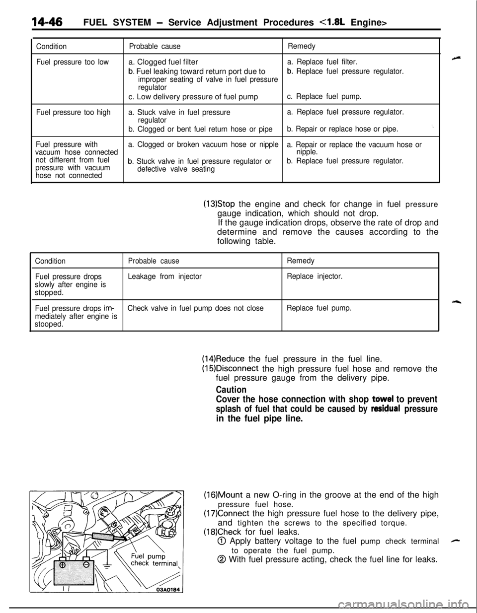
14-46FUEL SYSTEM - Service Adjustment Procedures <1.8L Engine>
Condition
Fuel pressure too low
Fuel pressure too highProbable causea. Clogged fuel filter
b. Fuel leaking toward return port due to
Remedy
a. Replace fuel filter.
improper seating of valve in fuel pressure
b. Replace fuel pressure regulator.
regulatorc. Low delivery pressure of fuel pump
c. Replace fuel pump.
a. Stuck valve in fuel pressurea. Replace fuel pressure regulator.
regulator
b. Clogged or bent fuel return hose or pipeb. Repair or replace hose or pipe.
‘.
Fuel pressure witha. Clogged or broken vacuum hose or nipple
a. Repair or replace the vacuum hose or
vacuum hose connectednipple.
not different from fuel
pressure with vacuum
b. Stuck valve in fuel pressure regulator orb. Replace fuel pressure regulator.
hose not connecteddefective valve seating
(13)Stop the engine and check for change in fuel pressure
gauge indication, which should not drop.
If the gauge indication drops, observe the rate of drop and
determine and remove the causes according to the
following table.
ConditionProbable causeRemedy
Fuel pressure dropsLeakage from injectorReplace injector.
slowly after engine is
stopped.
rqFuel pressure drops im-Check valve in fuel pump does not closeReplace fuel pump.
mediately after engine is
stooped.
(14)Reduce the fuel pressure in the fuel line.
(16)Disconnect the high pressure fuel hose and remove the
fuel pressure gauge from the delivery pipe.
Caution
Cover the hose connection with shop tdwel to prevent
splash of fuel that could be caused by residual pressure
in the fuel pipe line.
(16)Mount a new O-ring in the groove at the end of the high
pressure fuel hose.
(17)Connect the high pressure fuel hose to the delivery pipe,
and tighten the screws to the specified torque.
(18)Check for fuel leaks.
@ Apply battery voltage to the fuel pump check terminal
to operate the fuel pump.
@ With fuel pressure acting, check the fuel line for leaks.
-
Page 501 of 1216
FUEL SYSTEM - Service Adjustment Procedures <1.8L Engine>14-47
A
E3x>
/ )Engine speed
(rpm)1 FU446Engine speed (rpm)
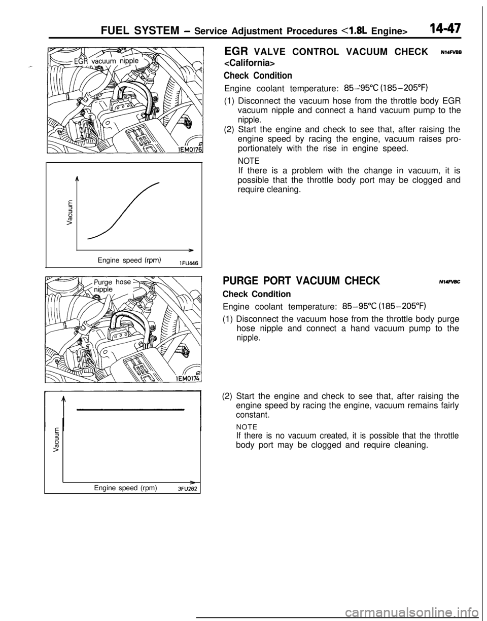
>3FU262EGR VALVE CONTROL VACUUM CHECK
Check ConditionEngine coolant temperature: 85-‘95”C (185-205°F)
(1) Disconnect the vacuum hose from the throttle body EGR
vacuum nipple and connect a hand vacuum pump to the
nipple.(2) Start the engine and check to see that, after raising the
engine speed by racing the engine, vacuum raises pro-
portionately with the rise in engine speed.
NOTEIf there is a problem with the change in vacuum, it is
possible that the throttle body port may be clogged and
require cleaning.
PURGE PORT VACUUM CHECKCheck ConditionN14FvBcEngine coolant temperature:
85-95°C (185-205°F)
(1) Disconnect the vacuum hose from the throttle body purge
hose nipple and connect a hand vacuum pump to the
nipple.(2) Start the engine and check to see that, after raising the
engine speed by racing the engine, vacuum remains fairly
constant.NOTE
If there is no vacuum created, it is possible that the throttlebody port may be clogged and require cleaning.
Page 503 of 1216
FUEL SYSTEM - Service Adjustment Procedures <2.0L Engine>14-49
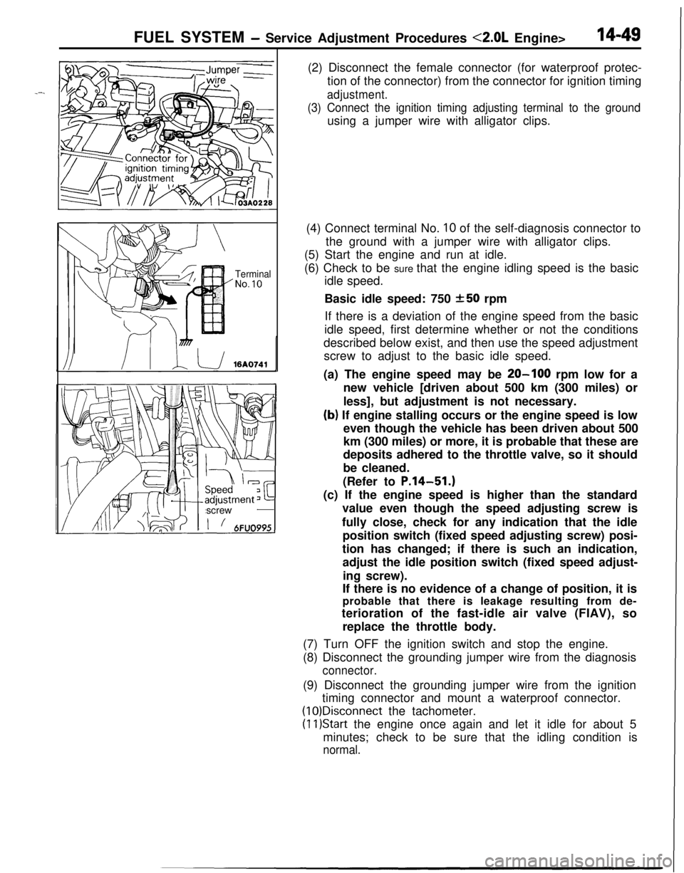
TerminalNo.10screw(2) Disconnect the female connector (for waterproof protec-
tion of the connector) from the connector for ignition timing
adjustment.
(3) Connect the ignition timing adjusting terminal to the groundusing a jumper wire with alligator clips.
(4) Connect terminal No.
10 of the self-diagnosis connector to
the ground with a jumper wire with alligator clips.
(5) Start the engine and run at idle.
(6) Check to be sure that the engine idling speed is the basic
idle speed.
Basic idle speed: 750
250 rpm
If there is a deviation of the engine speed from the basic
idle speed, first determine whether or not the conditions
described below exist, and then use the speed adjustment
screw to adjust to the basic idle speed.
(a) The engine speed may be
20-100 rpm low for a
new vehicle [driven about 500 km (300 miles) or
less], but adjustment is not necessary.
(b) If engine stalling occurs or the engine speed is low
even though the vehicle has been driven about 500
km (300 miles) or more, it is probable that these are
deposits adhered to the throttle valve, so it should
be cleaned.
(Refer to
P.14-51.)(c) If the engine speed is higher than the standard
value even though the speed adjusting screw is
fully close, check for any indication that the idle
position switch (fixed speed adjusting screw) posi-
tion has changed; if there is such an indication,
adjust the idle position switch (fixed speed adjust-
ing screw).
If there is no evidence of a change of position, it is
probable that there is leakage resulting from de-
terioration of the fast-idle air valve (FIAV), so
replace the throttle body.
(7) Turn OFF the ignition switch and stop the engine.
(8) Disconnect the grounding jumper wire from the diagnosis
connector.(9) Disconnect the grounding jumper wire from the ignition
timing connector and mount a waterproof connector.
(1O)Disconnect the tachometer.
(11)Star-t the engine once again and let it idle for about 5
minutes; check to be sure that the idling condition is
normal.