light MITSUBISHI ECLIPSE 1991 Repair Manual
[x] Cancel search | Manufacturer: MITSUBISHI, Model Year: 1991, Model line: ECLIPSE, Model: MITSUBISHI ECLIPSE 1991Pages: 1216, PDF Size: 67.42 MB
Page 552 of 1216
14-98FUEL SYSTEM -Fuel Tank
W636
Positioning projection03AO257
\03A0256SERVICE POINTS OF REMOVAL
N14G6AHl6. DISCONNECTION OF HIGH PRESSURE FUEL
HGSECaution
Cover the hose connection with rags to prevent splash
of fuel that could be caused by some residual pressure
in the fuel pipe line.
INSPECTIONN14GCAHl Check the hoses and the pipes for crack or damage.
l Check the fuel tank cap for malfunction.
l Check the fuel tank for deformation, corrosion or crack.
l Check the fuel tank for dust or foreign material.
NOTE
If the inside of the fuel tank is to be cleaned, use any one ofthe following:
(1) Kerosene
(2) Trichloroethylene
(3) A neutral emulsion type detergent
OVERFILL LIMITER (TWO-WAY VALVE)
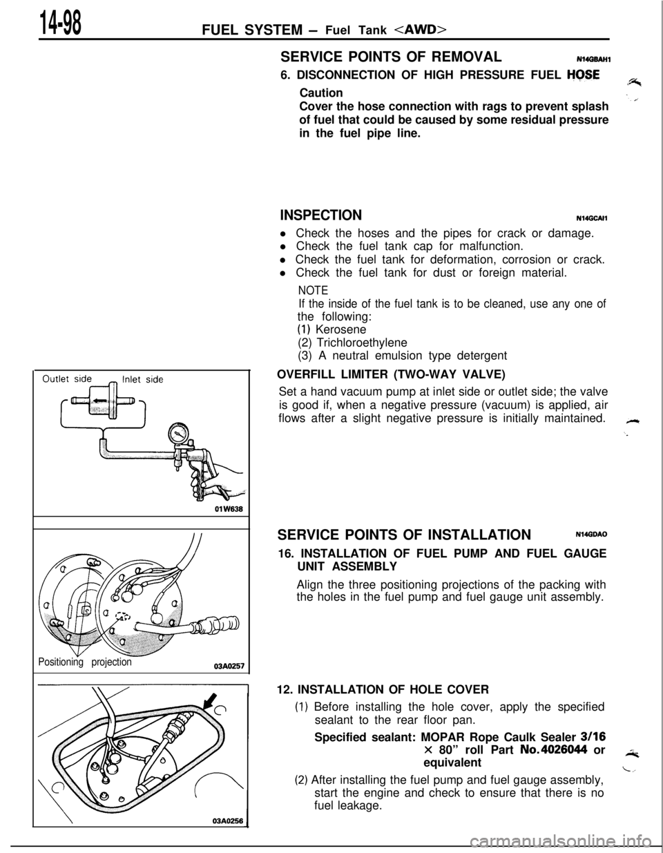
Set a hand vacuum pump at inlet side or outlet side; the valve
is good if, when a negative pressure (vacuum) is applied, air
flows after a slight negative pressure is initially maintained.
SERVICE POINTS OF INSTALLATION
N14GDAO16. INSTALLATION OF FUEL PUMP AND FUEL GAUGE
UNIT ASSEMBLY
Align the three positioning projections of the packing with
the holes in the fuel pump and fuel gauge unit assembly.
12. INSTALLATION OF HOLE COVER
) Before installing the hole cover, apply the specified
sealant to the rear floor pan.
Specified sealant: MOPAR Rope Caulk Sealer
3116
x 80” roll Part No.4026044 or
equivalent
!) After installing the fuel pump and fuel gauge assembly,
start the engine and check to ensure that there is no
fuel leakage.
Page 560 of 1216
14-106ENGINE CONTROL - Service Adjustment Procedures
TAir intakeAdjusting bolts
Idle switch03A,,2.8
07RQ024L
I
SERVICE ADJUSTMENT PROCEDM%,&ACCELERATOR CABLE
CNSPECTION AN&I ”ADJUSTMENT
For models equipped with the auto-cruise control systemreferto
P.14-136.(1) Turn air conditioner and lights OFF.
Inspect and adjust at no load.
2) Warm engine until stabilized at idle.
3) Confirm idle speed is at prescribed rpm.
4) Stop engine (ignition switch OFF).
5) Confirm there are no sharp bends in accelerator cable.
6) Check inner cable for correct slack.
7) If there is too much slack or no slack, adjust play by the
following procedures.
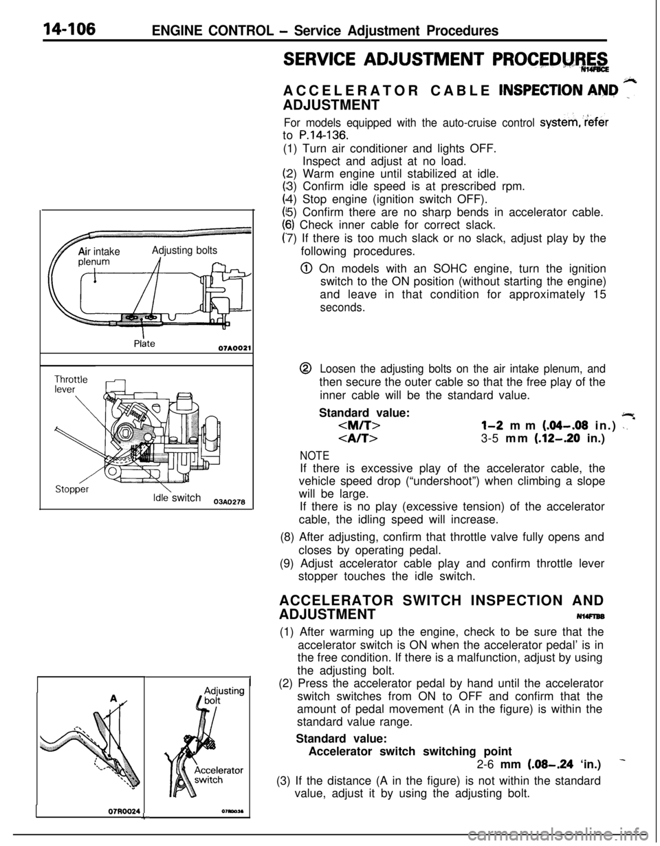
@ On models with an SOHC engine, turn the ignition
switch to the ON position (without starting the engine)
and leave in that condition for approximately 15
seconds.@
Loosen the adjusting bolts on the air intake plenum, andthen secure the outer cable so that the free play of the
inner cable will be the standard value.
Standard value:
jlr
3-5 mm (.12-.20 in.)
NOTEIf there is excessive play of the accelerator cable, the
vehicle speed drop (“undershoot”) when climbing a slope
will be large.
If there is no play (excessive tension) of the accelerator
cable, the idling speed will increase.
(8) After adjusting, confirm that throttle valve fully opens and
closes by operating pedal.
(9) Adjust accelerator cable play and confirm throttle lever
stopper touches the idle switch.
ACCELERATOR SWITCH INSPECTION AND
ADJUSTMENT
NlWlEB(1) After warming up the engine, check to be sure that the
accelerator switch is ON when the accelerator pedal’ is in
the free condition. If there is a malfunction, adjust by using
the adjusting bolt.
(2) Press the accelerator pedal by hand until the accelerator
switch switches from ON to OFF and confirm that the
amount of pedal movement (A in the figure) is within the
standard value range.
Standard value:
Accelerator switch switching point
2-6 mm
(.08-.24 ‘in.)
(3) If the distance (A in the figure) is not within the standard
value, adjust it by using the adjusting bolt.
Page 563 of 1216
AUTO-CRUISE CONTROL SYSTEM - Snecifications14-109
AUTO-CRUISE CONTROL SYSTEM
.-4.
SPECIFICATIONS
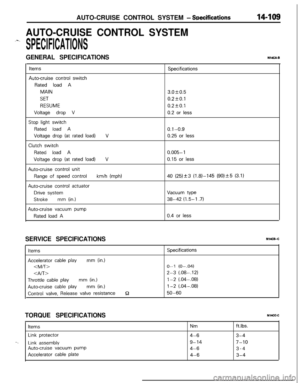
GENERAL SPECIFICATIONSNUCA-B
ItemsSpecifications
Auto-cruise control switch
Rated load AMAIN3.OkO.5
SET0.2fO.l
RESUME0.2kO.l
Voltage drop V0.2 or less
Stop light switch
Rated load A0.1-0.9
Voltage drop (at rated load)V0.25 or less
Clutch switch
Rated load A0.005-l
Voltage drop (at rated load)V0.15 or less
Auto-cruise control unit
Range of speed controlkm/h (mph)40 (25)_+3 (1.81-145 (90)_+5 (3.1)
Auto-cruise control actuator
Drive systemVacuum type
Strokemm (in.)38-42 (1.5-I .7)
Auto-cruise vacuum pump
Rated load A0.4 or less
SERVICE SPECIFICATIONSItems
Accelerator cable playmm (in.)
4l-bThrottle
cable playmm (in.)
Auto-cruise cable playmm (in.)
Control valve, Release valve resistanceQ
Specifications
O-l (O-.04)
2-3 (.08-,121
1-2 (.04-.08)
1-2 (.04-.08)
50-60
TORQUE SPECIFICATIONSN14CGCItems
Nmftlbs.
Link protector4-63-4-.
Link assembly9-147-10
Auto-cruise vacuum pump4-63-4
Accelerator cable plate4-63-4
Page 565 of 1216
AUTO-CRUISE CONTROL SYSTEM - Troubleshooting144w
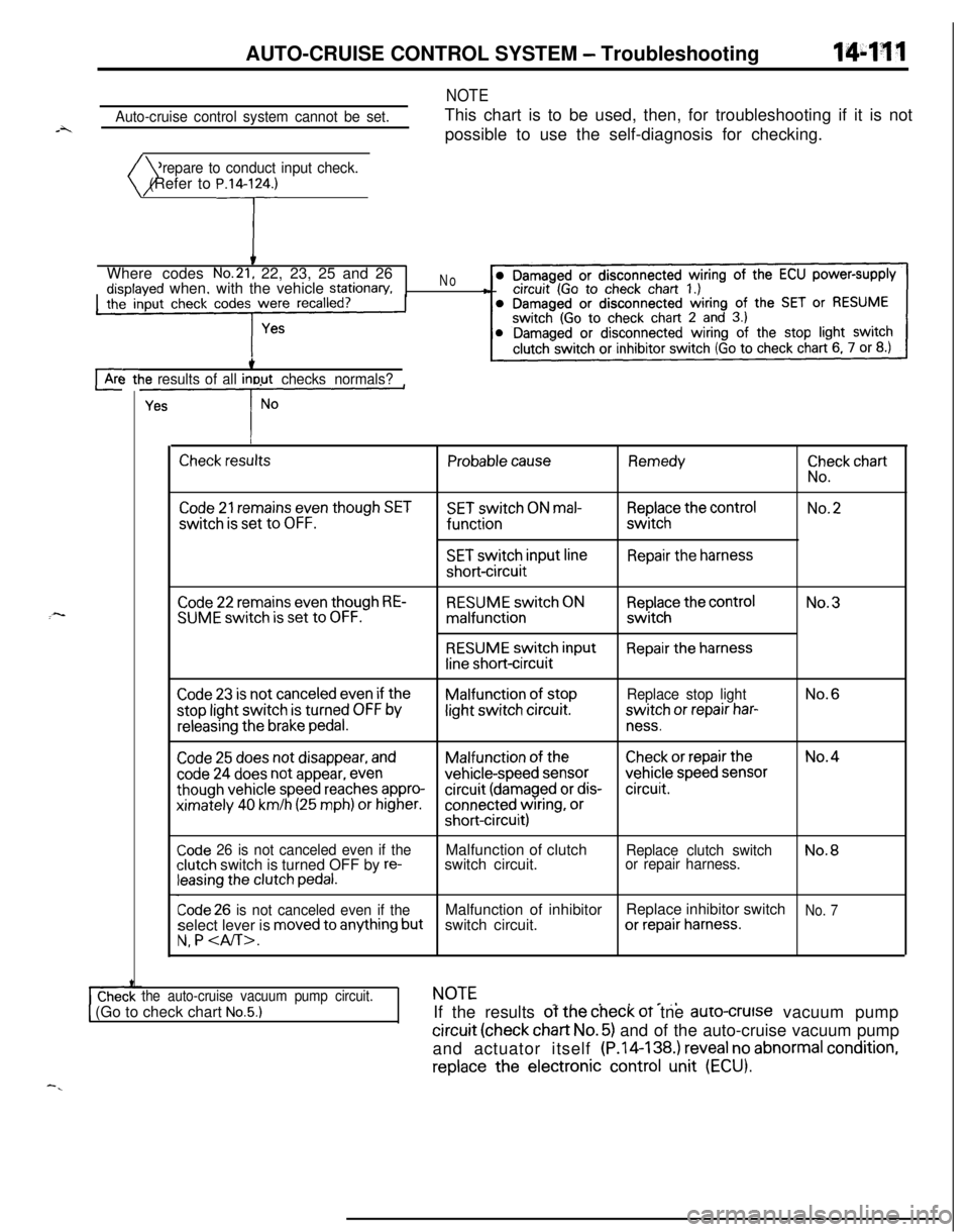
Auto-cruise control system cannot be set.
NOTEThis chart is to be used, then, for troubleshooting if it is not
possible to use the self-diagnosis for checking.
Prepare to conduct input check.
)( (Refer to P.14lrWhere codes
No.21, 22, 23, 25 and 26disolaved when, with the vehicle stationary,the’ input check codes were recalled?
‘#
No-8
cArc-3 ttie results of all inout checks normals?
L--y--
I
Check resultsProbable causeRemedy
ii”,:” chart
Code 21 remains even though SETSET switch ON mal-Replace the controlNo.2switch
is set to OFF.functionswitch
SET switch input lineRepair the harnessshort-circuit
:-Code 22 remains even though RE-SUME switch is set to OFF.RESUME switch ONmalfunction
RESUME switch input
line short-circuit
Replace the controlswitch
Repair the harnessNo.3
Code 23 is not canceled even if theMalfunction of stopReplace stop lightNo.6stop light switch
is turned OFF bylight switch circuit.switch or repair har-
releasing the brake pedal.ness.
Code 25 does not disappear, andMalfunction of theCheck or repair theNo.4
code 24 does not appear, evenvehicle-speed sensorvehicle speed sensor
though vehicle speed reaches appro-circuit (damaged or dis-circuit.ximately
40 km/h (25 mph) or higher.connected wiring, orshort-circuit)
Code 26 is not canceled even if theclutch switch is turned OFF by re-leasing the clutch pedal.Malfunction of clutch
switch circuit.
Replace clutch switchNo.8or repair harness.
Code 26 is not canceled even if theMalfunction of inhibitorReplace inhibitor switchNo. 7select lever is moved to anything butswitch circuit.or repair harness.
N, P
the auto-cruise vacuum pump circuit.NOTE_. . . e_,1 (Go to check chart No.5.)IIf the results of the check oT tne auro-crutse vacuum pump
circuit (check chart No. 5) and of the auto-cruise vacuum pump
and actuator itself (P.14-138.) reveal no abnormal
condition,replace
the electronic control unit (ECU).
-.
Page 566 of 1216

14-112AUTO-CRUISE CONTROL SYSTEM - Troubleshootina
Trouble symptomProbable causeCheck chart No.Remedy
l The set vehicle speed variesMalfunction of the vehi-No.4Repair the vehicle speec
greatly upward or downward.cle speed sensor circuitsensor system, or re-l “Hunching”
(repeated alternatingplace the part.
acceleration and deceleration)Malfunction of the
occurs after setting is made.speedometer cable orspeedometer drive gearAuto-cruise
vacuumNo.5Repair the auto-cruise
pump circuit poor con-vacuum pump, ortactreplace the part.Malfunction of the
auto-
cruise vacuum pumpMalfunction of the
ECU-Replace the ECU.
The auto-cruise control system is notDamaged or discon-If the input check codeRepair the harness or
canceled when the brake pedal isnetted wiring of theNo. 23 indicates a mal-replace the stop light
depressed.stop light switch inputfunction. No. 6switch.circuit; brake switch (forauto-cruise control) mal-function (short-circuit)Auto-cruise
vacuumNo. 5Repair the harness or
pump drive circuit short-replace the auto-cruisecircuitvacuum pump.Malfunction of the
ECU-Replace the ECU.
The auto-cruise control system is notDamaged or discon-If the input check codeRepair the harness, or
canceled when the clutch pedal isnetted wiring of clutchNo. 26 indicates a mal-repair or replace the
depressed. (vehicles with a manualswitch input circuitfunction. No. 8clutch switch.
transaxle)(It is canceled, however, when theClutch switch improper
brake pedal is depressed.)installation (won’tswitch ON)Malfunction of the
ECU-Replace the ECU.
The auto-cruise control system is notDamaged or discon-If the input check codeRepair the harness, orcanceled when the shift lever isnetted wiring of inhibi-No. 26 indicates a mal-repair or replace the in-
moved to the “N” position. (vehiclestor switch input circuitfunction. No.7hibitor switch.llvith an automatic transaxle)
[It is canceled, however, when theImproper adjustment of
Drake pedal is depressed.)inhibitor switchMalfunction of the
ECU-Replace the ECU.
Cannot decelerate by using the SETTemporary damaged orNo. 2Repair the harness orswitchdisconnected wiring ofreplace the SET switch.SET switch input circuitAuto-cruise
vacuumNo.5Repair the harness orpump circuit poor con-replace the auto-cruisetactvacuum pump andactuator.Malfunction of the auto-cruise vacuum pump
and actuator (includingclogging of negativepressure passage)Malfunction of the
ECU-Replace the ECU.
Page 567 of 1216
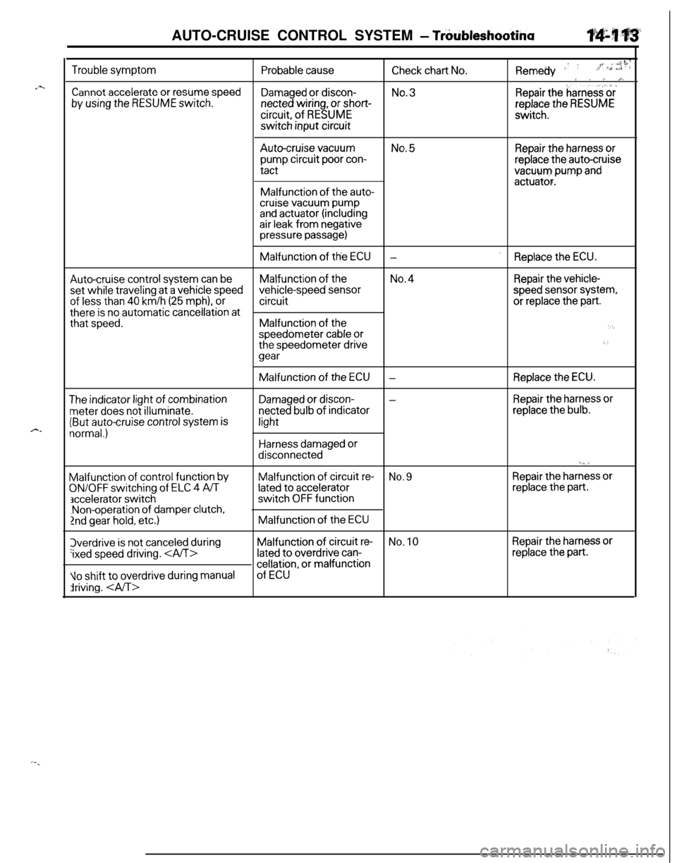
.z
c-AUTO-CRUISE CONTROL SYSTEM
- Tr6ubleshootina
Trouble symptom
Cannot accelerate or resume speed
by using the RESUME switch.
Probable cause
Damaged or discon-netted wiring, or short-circuit, of
RESUMEswitch input circuit
Remedy .’ ’-c liiCheck chart No.,;+ >,, a”:; : :
9 . /~ A%No.3.Repair theharness‘&
replace the RESUMEswitch.Auto-cruise
vacuumNo. 5Repair the harness orpump circuit poor con-replace the auto-cruisetact
vacuum,pump andactuator.Malfunction of the auto-cruise vacuum pumpand actuator (includingair leak from negativepressure passage)Malfunction of the
ECU.-Replace the ECU.
Auto-cruise control system can beMalfunction of theNo.4Repair the vehicle-set while
traveling at a vehicle speedvehicle-speed sensorspeed sensor system,
of less than 40 km/h (25 mph), orcircuitor replace the part.there
is no automatic cancellation atthat
speed.Malfunction of the‘I,speedometer cable orthe speedometer drive6 i
gear
The indicator light of combination
meter does not illuminate.
(But auto-cruise control system is
normal.)Malfunction
of control function by
ON/OFF switching of ELC 4 A/T
accelerator switch,Non-operation of damper clutch,
2nd gear hold, etc.)3verdrive
is not canceled during
‘ixed speed driving.
10 shift to overdrive during manual
driving. Malfunction of the
ECU-Replace the ECU.
Damaged or discon--Repair the harness or
netted bulb of indicatorreplace the bulb.light
Harness damaged ordisconnected
‘._,.Malfunction of circuit
re-No. 9Repair the harness or
lated to acceleratorreplace the part.switch
OFF functionMalfunction of the
ECUMalfunction of circuit
re-No. 10Repair the harness or
lated to overdrive can-replace the part.
cellation, or malfunction
of ECU
Page 571 of 1216
i-._AUTO-CRUISE CONTROL SYSTEM
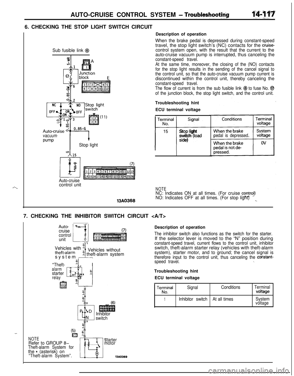
- Troubltyshootf$6. CHECKING THE STOP LIGHT SWITCH CIRCUIT
Sub fusible link @
vacuum
w-vStop light
Auto-cruisecontrol unit13A0366Description of operation
When the brake pedal is depressed during constant-speedtravel, the stop light switch’s (NC) contacts for the cruise-control system open, with the result that the current to the
auto-cruise vacuum pump is interrupted, thus canceling the
constant-speed travel.
At the same time, moreover, the closing of the (NO) contacts
for the stop light results in the sending of the cancel signal to
the control unit, so that the auto-cruise vacuum pump current is
discontinued within the control unit, thereby canceling the
constant-speed travel.
The flow of current is from the sub fusible link
@I to fuse No. @
of the junction block, the stop light switch, and the control unit.Troubleshooting hint
ECU terminal voltage
TerminalSignal
No.
15
t-i-
Stop light
switch (load
side)pedal is depressed.
NOTENC: Indicates ON at all times. (For cruise contra!)NO: Indicates OFF at all times. (For stop light)l,_7. CHECKING THE INHIBITOR SWITCH CIRCUIT
Auto-
cruise
controlunit
Vehicles with x
theft-alarmIVehicles without5 theft-alarm systemsystem br
*Theft-’ nI Ialarm, ._I
starterz
relayQlOF: N A_ 3
Inhibitor
switchDescription of operation
The inhibitor switch also functions as the switch for the starter.If the selector lever is moved to the “N” position during
constant-speed travel, current flows to the control unit, inhibitorswitch, theft-alarm starter relay (vehicles with theft-alarm
system), starter motor, and to ground; the cancel signal istherefore input to the control unit, thus canceling the constant-speed travel.5Troubleshooting hint
ECU terminal voltage
TeE!alSignalConditionsTerminalvoltage
1Inhibitor switchAt all timesSystemvoltage
C.starter
motor13A036BNOTERefer to GROUP 8-Theft-alarm System forthe + (asterisk) on“Theft-alarm System”.
Page 575 of 1216

AUTO-CRUISE CONTROL SYSTEM - Troubleshooting'14421
16A065i
Auto-cruise
16LOOS
SELF-DIAGNOSIS CHECKSelf-diagnosis checking is performed when there has been an
automatic cancellation, without cancel switch
operati’on.(1) The following method can be used for checking the
diagnosis. Note that the diagnosis check connector is
located under the driver’s side instrument panel.
Connect a voltmeter between the ground terminal and the
terminal for auto-cruise control of the diagnosis check
connector.It is possible to discover which circuit is the cause of the
cancellation by verifying the indication shown by the
voltmeter with the display patterns shown on the next
page.(2) When the diagnosis code No. is displayed, inspect accord-
ing to the inspection chart No. related to each code No.
NOTECanceling the diagnosis codes
The diagnosis codes remain in memory until the battery is
turned off but they can be canceled in the following ways
without disconnecting the battery terminals.
1. By turning on the ignition switch
2.By turning the cruise switch ON while the SET switch is ONand then, within 1 second, turning the RESUME switch
ON. (Put into condition for input check reception)
3.By turning ON set SET switch and stop light switch at the
same time and continuing the ON condition for 5 seconds
or more.
4.By checking that the diagnosis codes are canceled using avoltmeter.
Page 578 of 1216
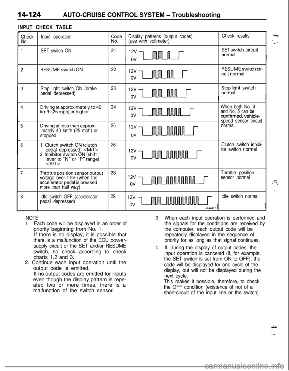
14-124AUTO-CRUISE CONTROL SYSTEM - Troubleshooting
INPUT CHECK TABLE
CheckInput operationiI!eDisplay patterns (output codes)Check results
No.(use with voltmeter)
1SET switch ON21X:Gayitch circuit
2RESUME switch ON2212vRESUME switch cir-cuit
normalov
3Stop light switch ON (brake23
pedal depressed)
;;pl;yht switch
4Driving at approximately to 4024When both No. 4
km/h (25 mph) or higherand No. 5 can be
co,nfirmed, vehicle-.speed sensor circuit
5Driving at less than approx-2512vnormal.
imately 40 km/h (25 mph) or
stopped
ov
61. Clutch switch ON (clutch26Clutch switch inhibi-
pedal depressed)
2. Inhibitor switch ON (shift12vlever to “N” or “P” range)ov
-aIT>
7Throttle position sensor output28
voltage over 1.5V (when theThrottle positionsensor normal
accelerator pedal is pressedmore than half way)
?Idle switch OFF (accelerator29Idle switch normal
pedal depressed)
NOTE
1.Each code will be displayed in an order ofpriority beginning from No. 1.
If there is no display, it is possible that
there is a malfunction of the ECU power-
supply circuit or the SET and/or RESUMEswitch, so check according to check
charts
1,2 and 3.
2. Continue each input operation until the
output code is emitted.
If no output codes are emitted for inputs
even though the display pattern is repe-
ated two or more times, there is a
malfunction of the switch sensor.
3.When each input operation is performed and
the signals for the conditions are received by
the computer, each output code will be
repeatedly displayed in the sequence of
priority for as long as that signal continues.
4.If, during the display of output codes, the
input operation is canceled (if, for example,
the SET switch is set from ON to OFF), the
code will be displayed for one cycle of the
display, but will not be displayed during the
next cycle.
This makes it possible, therefore, to check
the OFF condition (existence of not of a
short-circuit of the input line or the switch).
Page 579 of 1216
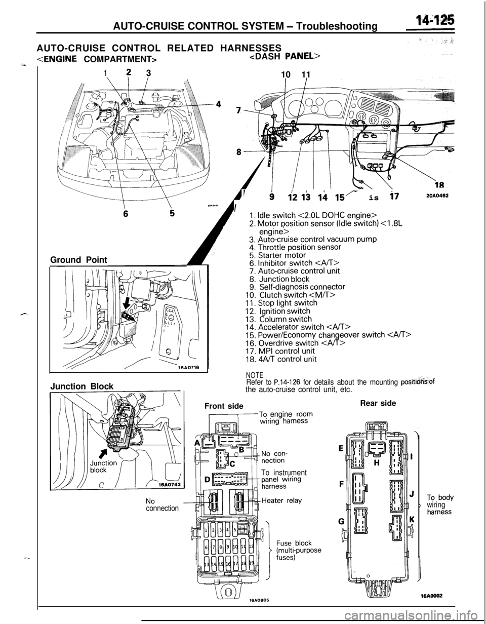
AUTO-CRUISE CONTROL SYSTEM - Troubleshooting
AUTO-CRUISE CONTROL RELATED HARNESSES
1? 3
10 11
Ground Point
--
, ’
112 I$ ii 15r is i72OAO402
1. Idle switch <2.0L DOHC engine>
2. Motor position sensor (Idle switch)
11. Stop light switch12.Ignition switch
13.Column switch14. Accelerator switch 15. Power/Economy changeover switch
16. Overdrive switch
18. 4Aff control unit
NOTERefer to P.14-126 for details about the mounting positicjkof
the auto-cruise control unit, etc.Junction Block
NoconnectionFront side
,-To engineroom
To instrumentRear side
)To bodywiringharness