light MITSUBISHI ECLIPSE 1991 Manual PDF
[x] Cancel search | Manufacturer: MITSUBISHI, Model Year: 1991, Model line: ECLIPSE, Model: MITSUBISHI ECLIPSE 1991Pages: 1216, PDF Size: 67.42 MB
Page 580 of 1216
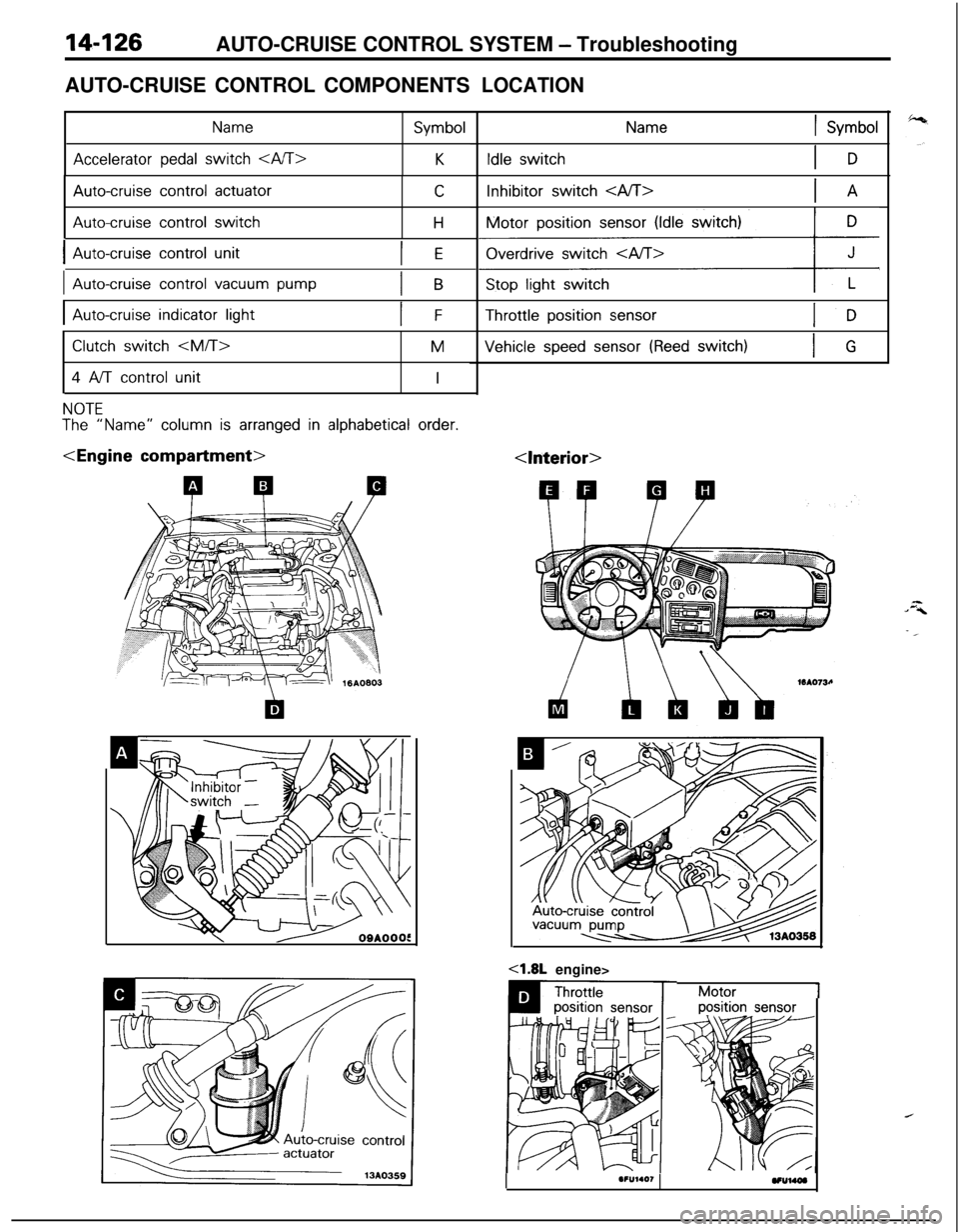
14-126AUTO-CRUISE CONTROL SYSTEM - Troubleshooting
AUTO-CRUISE CONTROL COMPONENTS
Name
Accelerator pedal switch
Symbol
K
Auto-cruise control actuator
Auto-cruise control switch
C
H
IAuto-cruise control unitIE
IAuto-cruise control vacuum pumpIB
IAuto-cruise indicator lightIF
Clutch switch
4 A/T control unit
M
I
NOTE
The “Name” column is arranged in alphabetical order.
LOCATION
1 Symbol
Idle switchIDInhibitor switch
Motor position
sensor (Idle switch)
ziz&Gy+Throttle position
sensor
Vehicle speed sensor (Reed switch)IG
Motor1position sensor
I.F”l.O,VUUW
Page 581 of 1216
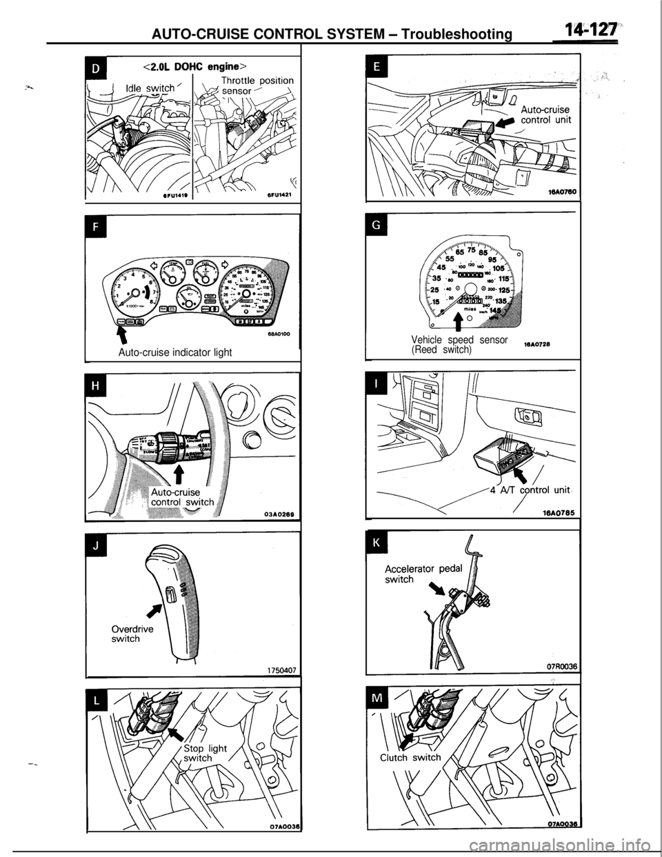
AUTO-CRUISE CONTROL SYSTEM - Troubleshooting
--
Auto-cruise indicator light
Vehicle speed sensor
(Reed switch)WA0728
l/4’NTj$trol unit-
Page 586 of 1216

14-132AUTO-CRUISE CONTROL SYSTEM - Troubleshooting
4ci
IGNITIONSWITCHtlGl)
CR”
I
AUTO-CRUISE
CONTROL UNIT
c-01
B
1COLUMN SWITCH
AUTO-CRUISE
>CONTROL SWITCH
T C-06
I
\,4
STOPLIGHT '~------
"ITCH OP?“ONc-03ON
+I1
2
hS3 O
0
s0.65-G
SUB 1LINK
!i
L!
0
L15A
I0.85-GW-0.85-GW1
!5
OPEN
CONNECTORc-02
1IQI2E
;SIBLE
qB
1 d-47
J/B6
C-55
16
AUTO-CRUISEc-01CONTROL UNIT
Page 589 of 1216
AUTO-CRUISE CONTROL SYSTEM L service Adjustkt Procedw&
03A0258
YSET
03AO258
03AO250
SET
03A025t
JI
SERVICE ADJUSTMENT PROCEDURESNl4FUU
AUTO-CRUISE CONTROL SYSTEM INSPECTION
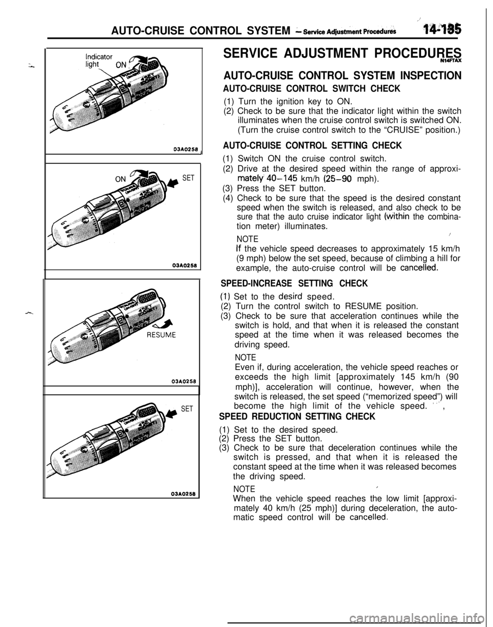
AUTO-CRUISE CONTROL SWITCH CHECK(1) Turn the ignition key to ON.
(2) Check to be sure that the indicator light within the switch
illuminates when the cruise control switch is switched ON.
(Turn the cruise control switch to the “CRUISE” position.)
AUTO-CRUISE CONTROL SETTING CHECK(1) Switch ON the cruise control switch.
(2) Drive at the desired speed within the range of approxi-
mately 40-145 km/h (25-90 mph).
(3) Press the SET button.
(4) Check to be sure that the speed is the desired constant
speed when the switch is released, and also check to be
sure that the auto cruise indicator light (tithin the combina-tion meter) illuminates.
NOTE1(
If the vehicle speed decreases to approximately 15 km/h
(9 mph) below the set speed, because of climbing a hill for
example, the auto-cruise control will be
cancelled.
SPEED-INCREASE SETTING CHECK
(‘1) Set to the desird speed.
(2) Turn the control switch to RESUME position.
(3) Check to be sure that acceleration continues while the
switch is hold, and that when it is released the constant
speed at the time when it was released becomes the
driving speed.
NOTEEven if, during acceleration, the vehicle speed reaches or
exceeds the high limit [approximately 145 km/h (90
mph)], acceleration will continue, however, when the
switch is released, the set speed (“memorized speed”) will
become the high limit of the vehicle speed.
’ ” ,
SPEED REDUCTION SETTING CHECK(1) Set to the desired speed.
(2) Press the SET button.
(3) Check to be sure that deceleration continues while the
switch is pressed, and that when it is released the
constant speed at the time when it was released becomes
the driving speed.
NOTEIWhen the vehicle speed reaches the low limit [approxi-
mately 40 km/h (25 mph)] during deceleration, the auto-
matic speed control will be
cancelled.
Page 592 of 1216
14-138AUTO-CRUISE CONTROL SYSTEM - Service Adjustment Procedures
07A0051
07AOO50
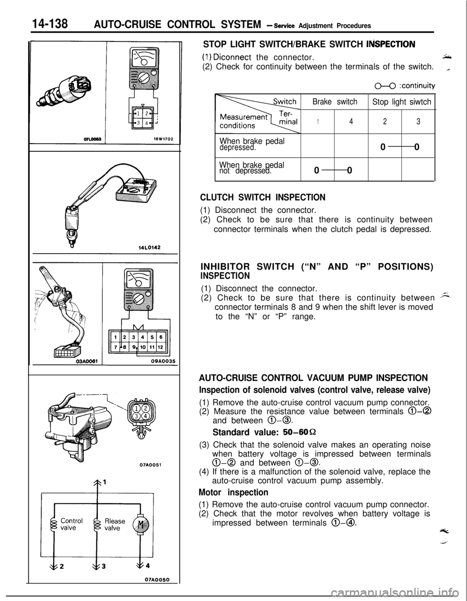
STOP LIGHT SWITCH/BRAKE SWITCH ItiSPECTlON
(1) Diconnect the connector.66(2) Check for continuity between the terminals of the switch.
_
When brake pedaldepressed.
When brake pedalnot depressed.
m :continuity
Brake switch
Stop light siwtch
142300
00
CLUTCH SWITCH INSPECTION(1) Disconnect the connector.
(2) Check to be sure that there is continuity between
connector terminals when the clutch pedal is depressed.
INHIBITOR SWITCH (“N” AND “P” POSITIONS)
INSPECTION(1) Disconnect the connector.
(2) Check to be sure that there is continuity between
Aconnector terminals 8 and 9 when the shift lever is moved
to the “N” or “P” range.
AUTO-CRUISE CONTROL VACUUM PUMP INSPECTION
Inspection of solenoid valves (control valve, release valve)(1) Remove the auto-cruise control vacuum pump connector.
(2) Measure the resistance value between terminals
0-0and between
0-0.
Standard value: 50-6OQ
(3) Check that the solenoid valve makes an operating noise
when battery voltage is impressed between terminals
0-0 and between 0-0.(4) If there is a malfunction of the solenoid valve, replace the
auto-cruise control vacuum pump assembly.
Motor inspection(1) Remove the auto-cruise control vacuum pump connector.
(2) Check that the motor revolves when battery voltage is
impressed between terminals @-@I.
@k
Page 594 of 1216
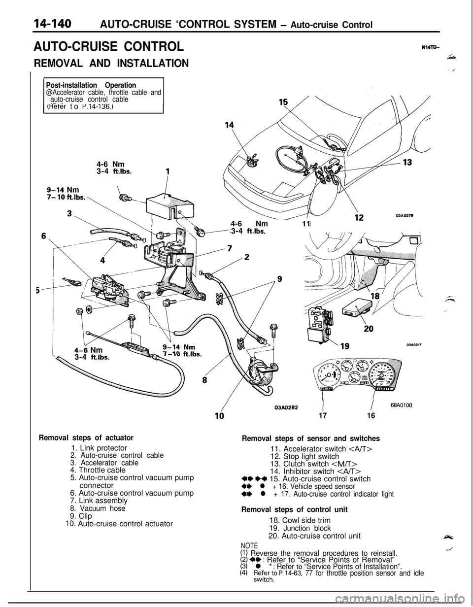
14-140AUTO-CRUISE ‘CONTROL SYSTEM - Auto-cruise Control
AUTO-CRUISE CONTROLN14TLL
REMOVAL AND INSTALLATION
Post-installation Operation@Accelerator cable, throttle cable andauto-cruise control cableI- _1 (Keter to P.14-136.)4-6 Nm
3-4
ft:lbs.
9-14 Nm7- 10 ft.lbs. \
\ I- \ ‘.\-4-6 Nm - 11
3-4 ft.lbs.
4-6 Nmw3-4 ft.lbs.--Qc ‘”
Removal steps of actuator1. Link protector
2. Auto-cruise control cable
3. Accelerator cable4. Throttle cable
5. Auto-cruise control vacuum pump
connector
6. Auto-cruise control vacuum pump
7. Link assembly
8. Vacuum hose9. Clip
IO. Auto-cruise control actuator
/03AO28210II68AOlOO
1716
Removal steps of sensor and switches11. Accelerator switch
12. Stop light switch
13. Clutch switch
Removal steps of control unit18. Cowl side trim
19. Junction block20. Auto-cruise control unit
NOTE(1) Reverse the removal procedures to reinstall.(2) +* : Refer to “Service Points of Removal”(3) l * : Refer to “Service Points of Installation”.(4)%l;;to P. 14-63, 77 for throttle position sensor and idle
Page 595 of 1216
AUTO-CRUISE CONTROL SYSTEM - Auto-cruise Control14-141
SERVICE POINTS OF REMOVAL?trmNWpBC
15. REMOVAL OF AUTO-CRUISE CONTROL SWITCHRefer to GROUP
8-Column Switch.
16. REMOVAL OF VEHICLE SPEED SENSORRefer to GROUP
8-Meters and Gauges.
17. REMOVAL OF AUTO-CRUISE CONTROL INDICATOR
LIGHTRefer to GROUP
8-Meters and Gauges.
INSPECTIONN14lDCEl Check the inner and outer cable for damage.
l Check the cable for smooth movement.
l Check the link protector for damage.
CHECKING THE AUTO-CRUISE CONTROL ACTUATORRefer to
P.14-138.
SERVICE POINTS OF INSTALLATIONN14TDDDD
17. INSTALLATION OF AUTO-CRUISE CONTROL INDICA-
TOR LIGHTRefer to GROUP
8-Meters and Gauges.
16. INSTALLATION OF AUTO-CRUISE CONTROL SWITCHRefer to GROUP
8-Column Switch.
15. INSTALLATION OF VEHICLE SPEED SENSORRefer to GROUP
8-Meter and Gauges.
Page 612 of 1216
17-2REAR SUSPENSION
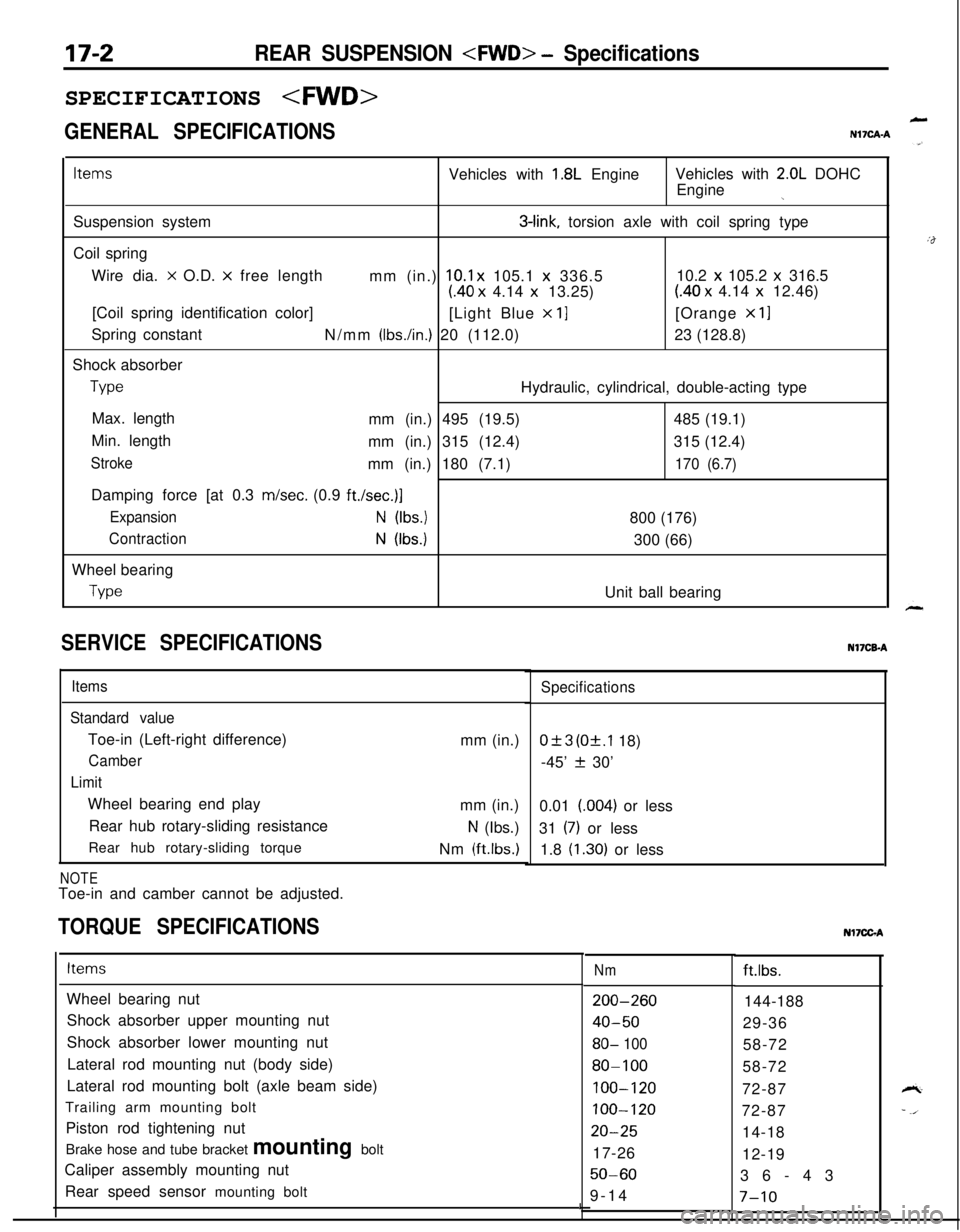
GENERAL SPECIFICATIONS
LN17CAA
ItemsVehicles with 1.8L EngineVehicles with 2.0L DOHC
Engine
jSuspension system
3-link, torsion axle with coil spring type
Coil spring
Wire dia.
x O.D. x free length
mm (in.) 10.1 x 105.1 x 336.510.2 x 105.2 x 316.5
(40 x 4.14 x 13.25)(40 x 4.14 x 12.46)
[Coil spring identification color]
[Light Blue
x 11[Orange x 11Spring constant
N/mm
(Ibs./in.) 20 (112.0)23 (128.8)
Shock absorber
TypeHydraulic, cylindrical, double-acting type
Max. length
mm (in.) 495 (19.5)485 (19.1)
Min. length
mm (in.) 315 (12.4)315 (12.4)
Strokemm (in.) 180 (7.1)170 (6.7)Damping force [at 0.3 m/set. (0.9
ft./set.)]
ExpansionN (Ibs.)800 (176)
ContractionN (Ibs.)300 (66)
Wheel bearing
TypeUnit ball bearing
SERVICE SPECIFICATIONS
Items
Standard valueToe-in (Left-right difference)
Camber
LimitWheel bearing end play
Rear hub rotary-sliding resistance
Rear hub rotary-sliding torque
NOTEToe-in and camber cannot be adjusted.mm (in.)
mm (in.)
N (Ibs.)
Nm
(ftlbs.)
TORQUE SPECIFICATIONS
Specifications
0+3 (Of.1 18)
-45’
f 30’
0.01 (004) or less
31
(7) or less
1.8
(1.30) or lessNI’ICB-A
ItemsNmft.lbs.
Wheel bearing nut
Shock absorber upper mounting nut
Shock absorber lower mounting nut
Lateral rod mounting nut (body side)
Lateral rod mounting bolt (axle beam side)
Trailing arm mounting bolt
Piston rod tightening nut
Brake hose and tube bracket mounting bolt
Caliper assembly mounting nut
Rear speed sensor mounting bolt
200-260
40-50
80- 100
80-100
100-120
100-120
20-2517-26
50-609-14144-188
29-36
58-72
58-72
72-87
72-87
14-18
12-19
36-43
I7-10
Nl7CGA
Page 616 of 1216
17-6REAR SUSPENSION
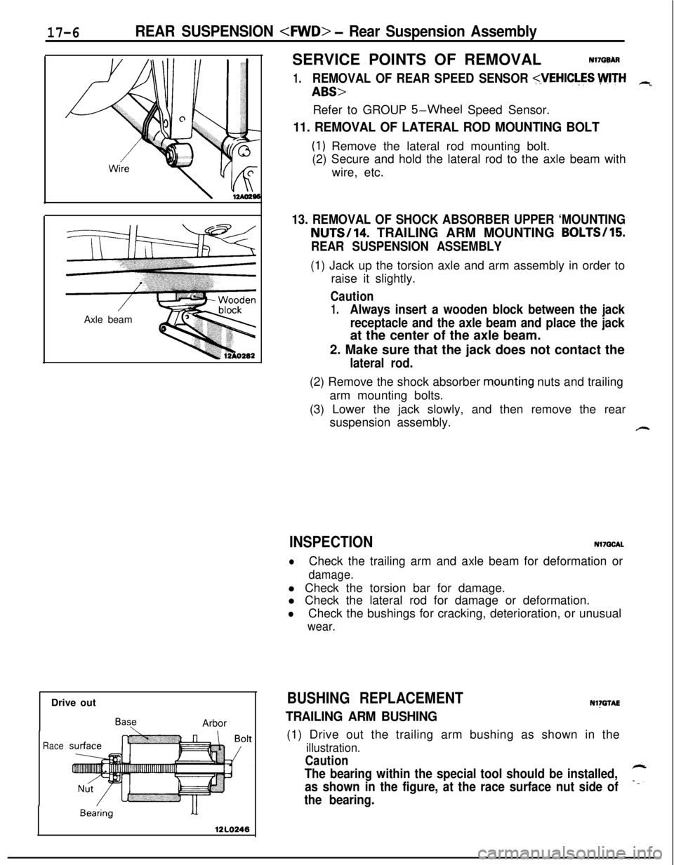
Drive out
BayArbor
Race
BearingSERVICE POINTS OF REMOVAL
Nl7QBh
1.REMOVAL OF REAR SPEED SENSOR
5-Wheel Speed Sensor.
11. REMOVAL OF LATERAL ROD MOUNTING BOLT
(1) Remove the lateral rod mounting bolt.
(2) Secure and hold the lateral rod to the axle beam with
wire, etc.
13. REMOVAL OF SHOCK ABSORBER UPPER ‘MOUNTINGNUTS/14. TRAILING ARM MOUNTING BOLTS/15
REAR SUSPENSION ASSEMBLY(1) Jack up the torsion axle and arm assembly in order to
raise it slightly.
Caution
1.Always insert a wooden block between the jack
receptacle and the axle beam and place the jackat the center of the axle beam.
2. Make sure that the jack does not contact the
lateral rod.(2) Remove the shock absorber
m,ounting nuts and trailing
arm mounting bolts.
(3) Lower the jack slowly, and then remove the rear
suspension assembly.
#-
INSPECTIONNl7QCAL
lCheck the trailing arm and axle beam for deformation or
damage.l Check the torsion bar for damage.
l Check the lateral rod for damage or deformation.
lCheck the bushings for cracking, deterioration, or unusual
wear.
BUSHING REPLACEMENTNl)GTAE
TRAILING ARM BUSHING(1) Drive out the trailing arm bushing as shown in the
illustration.
Caution
The bearing within the special tool should be installed,
as shown in the figure, at the race surface nut side of7
the bearing.
Page 618 of 1216
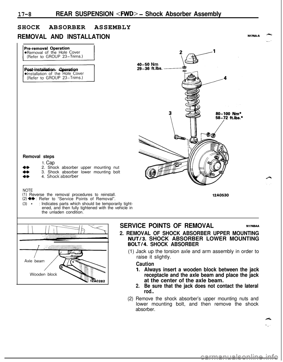
17-8REAR SUSPENSION
REMOVAL AND INSTALLATIONN17NA-A
Post-installation Operation
Removal steps
1. Cap
::2. Shock absorber upper mounting nut
3. Shock absorber lower mounting bolta*4. Shock.absorber
NOTE(I) Reverse the removal procedures to reinstall.(2) ** : Refer to “Service Points of Removal”.
(3) *: Indicates parts which should be temporarily tight-
ened, and then fully tightened with the vehicle in
the unladen condition.
40-50 Nm29-36 ft.lbs.
12A0530
SERVICE POINTS OF REMOVALNI’INBAA
2. REMOVAL OF SHOCK ABSORBER UPPER MOUNTINGNUT/3. SHOCK ABSORBER LOWER MOUNTING
BOLT/4. SHOCK ABSORBER(1) Jack up the torsion axle and arm assembly in order to
raise it slightly.
Caution
1.Always insert a wooden block between the jack
receptacle and the axle beam and place the jackat the center of the axle beam.
2.Be sure that the jack does not contact the lateral
rod..
(2) Remove the shock absorber’s upper mounting nuts andlower mounting bolt, and then remove the shock
absorber.