light MITSUBISHI ECLIPSE 1991 Service Manual
[x] Cancel search | Manufacturer: MITSUBISHI, Model Year: 1991, Model line: ECLIPSE, Model: MITSUBISHI ECLIPSE 1991Pages: 1216, PDF Size: 67.42 MB
Page 898 of 1216
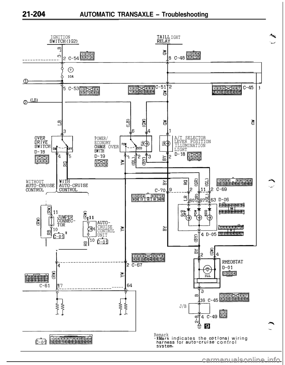
21-204AUTOMATIC TRANSAXLE - Troubleshooting
c;_----__---___-.
IGNITIONSWITCH(IG2)0
?
3E-7r
0
1UA
\IEjC-53mJ
ca (LB)
POWER/
ECONOMY
;$;;E OVER "r-
D-19A, .
12l!i3Fl3453$
,F
IGHT
3 19 ~lo~ll~l2~la~lq1qls
E
A/T SELECTOR
LEVER POSITION
ILLUMINATIONLIGHT
WITHOUTAU;iUi~;UISE
hf---
II
sP5 11
LIEI
AUTO-
CRUISE
CONTROL
UNIT
Y
-t
______--___---__--------
4
gF
C-61 57_______-__-----_---_-----
J/B
Remark**Mark indicates the oPtional wiringFEI~~I;S for auto-cruise control
Page 905 of 1216
AUTOMATIC TRANSAXLE - Service Adjustment Procedures21-21109A0146
OQMOO45
control lever
control lever
5 mm
Section A-A
(2 in.)Manual
controllever
Switch body
SHIFT LOCK MECHANISM CHECKN21FVAA
1.
2.
3.
4.Check to be sure that, under the following conditions, the
select lever cannot be moved from the
“P” position to any
other position.
Ignition key position: “ACC”
Brake pedal: Not depressedButton: Pressed
Check to be sure that, under the following conditions, the
select lever can be moved smoothly from the “P” position
to other position.
Ignition key position: “ACC”
Brake pedal: Depressed
Button: Pressed
Check to be sure that, under the following conditions, the
select lever can be moved smoothly from the “R” position
to the “P” position.
Ignition key position: “ACC”
Brake pedal: Released
Button: Pressed
If a malfunction is discovered when following the above
checking procedures, either adjust or check the shift lock
cable mechanism. (Refer to
P.21-220.)
INHIBITOR SWITCH ADJUSTMENTNZlFKAJ
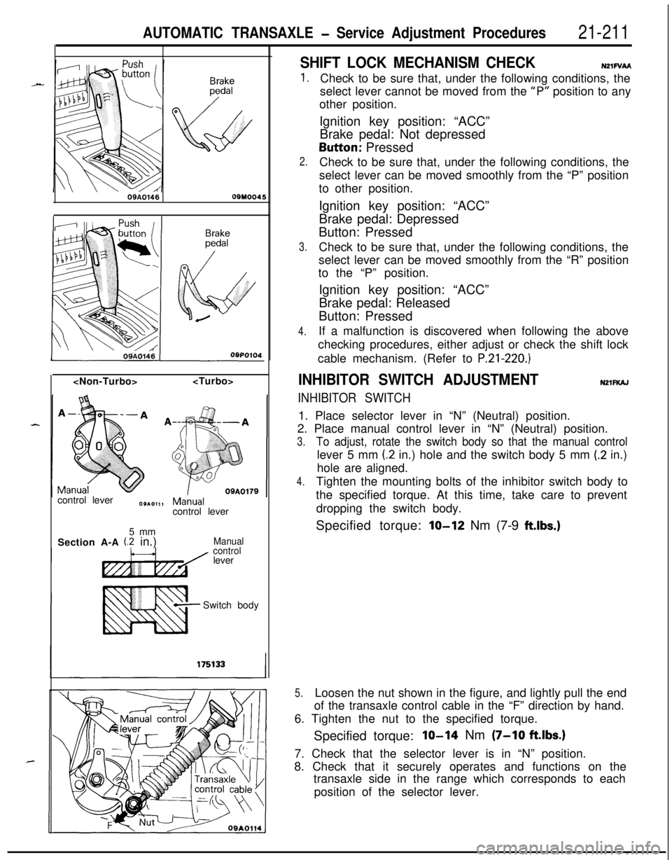
INHIBITOR SWITCH1. Place selector lever in “N” (Neutral) position.
2. Place manual control lever in “N” (Neutral) position.
3.To adjust, rotate the switch body so that the manual controllever 5 mm
(2 in.) hole and the switch body 5 mm (.2 in.)
hole are aligned.
4.Tighten the mounting bolts of the inhibitor switch body to
the specified torque. At this time, take care to prevent
dropping the switch body.
Specified torque:
lo-12 Nm (7-9 ftlbs.)
5.Loosen the nut shown in the figure, and lightly pull the end
of the transaxle control cable in the “F” direction by hand.
6. Tighten the nut to the specified torque.
Specified torque:
IO-14 Nm (7-10 ftlbs.)7. Check that the selector lever is in “N” position.
8. Check that it securely operates and functions on the
transaxle side in the range which corresponds to each
position of the selector lever.
Page 914 of 1216
AUTOMATIC TRANSAXLE - Transaxle Control
:lemotJnt
\\ \09R0058
09AO143
/’
\
’ CoverCoverKey interlock cableOSA0125
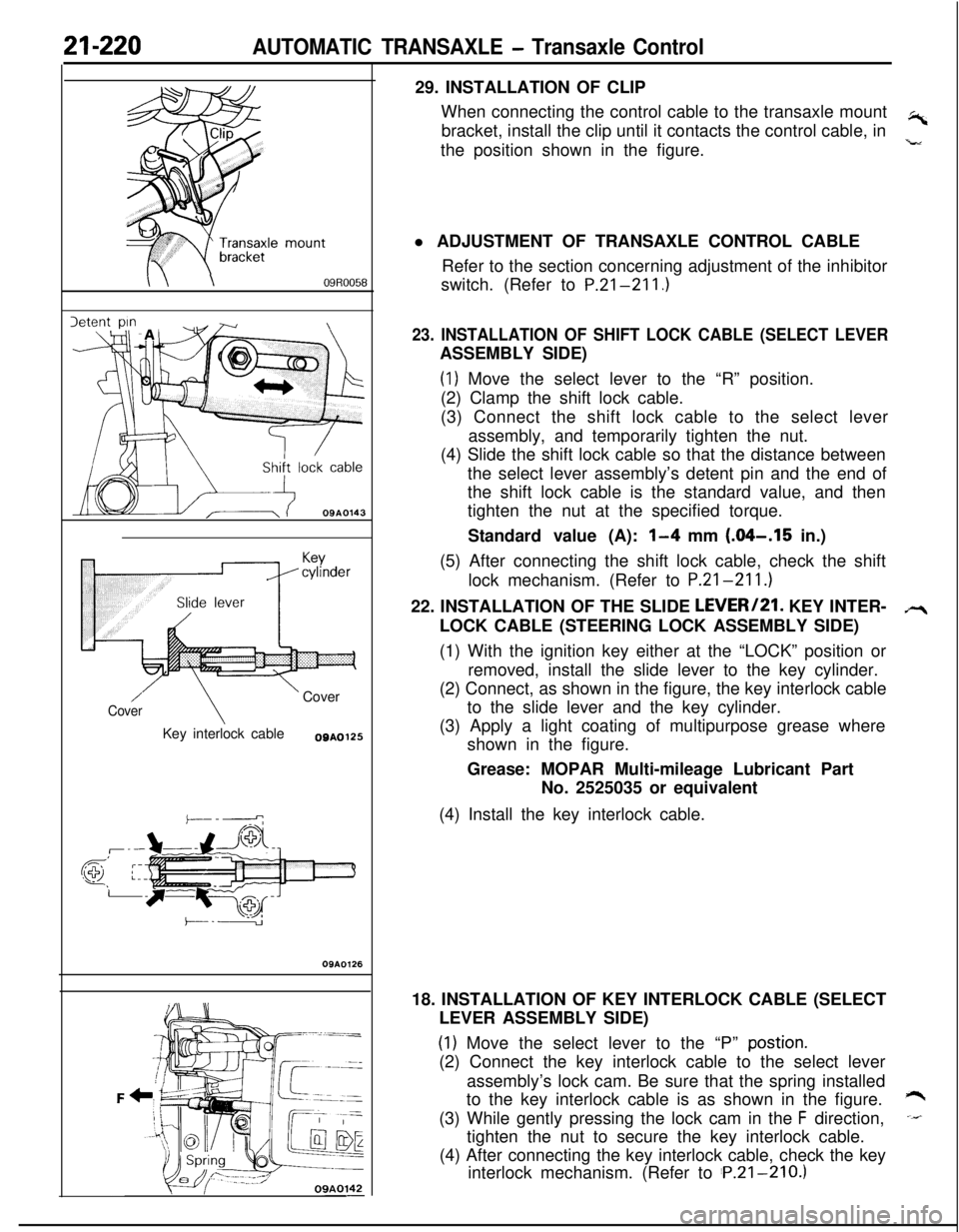
OSAO12629. INSTALLATION OF CLIP
When connecting the control cable to the transaxle mount
,-bracket, install the clip until it contacts the control cable, in
the position shown in the figure.
,”l ADJUSTMENT OF TRANSAXLE CONTROL CABLE
Refer to the section concerning adjustment of the inhibitor
switch. (Refer to P.21-211.)
23. INSTALLATION OF SHIFT LOCK CABLE (SELECT LEVERASSEMBLY SIDE)
(1) Move the select lever to the “R” position.
(2) Clamp the shift lock cable.
(3) Connect the shift lock cable to the select lever
assembly, and temporarily tighten the nut.
(4) Slide the shift lock cable so that the distance between
the select lever assembly’s detent pin and the end of
the shift lock cable is the standard value, and then
tighten the nut at the specified torque.
Standard value (A):
l-4 mm (.04-.I5 in.)
(5) After connecting the shift lock cable, check the shift
lock mechanism. (Refer to P.21-211.)
22. INSTALLATION OF THE SLIDE LEVERI21. KEY INTER-
LOCK CABLE (STEERING LOCK ASSEMBLY SIDE)
(1) With the ignition key either at the “LOCK” position or
removed, install the slide lever to the key cylinder.
(2) Connect, as shown in the figure, the key interlock cable
to the slide lever and the key cylinder.
(3) Apply a light coating of multipurpose grease where
shown in the figure.
Grease: MOPAR Multi-mileage Lubricant Part
No. 2525035 or equivalent
(4) Install the key interlock cable.
18. INSTALLATION OF KEY INTERLOCK CABLE (SELECT
LEVER ASSEMBLY SIDE)
(1) Move the select lever to the “P” postion.(2) Connect the key interlock cable to the select lever
assembly’s lock cam. Be sure that the spring installed
to the key interlock cable is as shown in the figure.
*(3) While gently pressing the lock cam in the
F direction,-tighten the nut to secure the key interlock cable.
(4) After connecting the key interlock cable, check the key
interlock mechanism. (Refer to ‘P.21-210.)
Page 948 of 1216
AUTOMATIC TRANSAXLE - Transaxle Assemblv
Solder
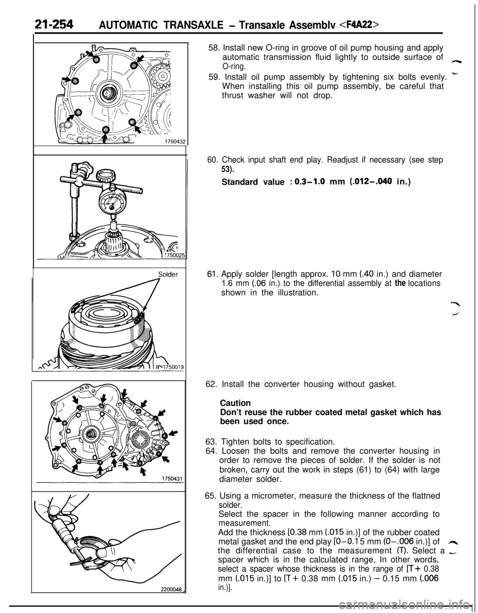
220004858. Install new O-ring in groove of oil pump housing and apply
automatic transmission fluid lightly to outside surface of
O-ring.e59. Install oil pump assembly by tightening six bolts evenly.
i-When installing this oil pump assembly, be careful that
thrust washer will not drop.
60. Check input shaft end play. Readjust if necessary (see step
53).Standard value
: 0.3-1.0 mm (.012-,040 in.)
61, Apply solder [length approx. 10 mm (40 in.) and diameter
1.6 mm (.06 in.) to the differential assembly at the locationsshown in the illustration.
“I
-4--J62. Install the converter housing without gasket.
Caution
Don’t reuse the rubber coated metal gasket which has
been used once.
63. Tighten bolts to specification.
64. Loosen the bolts and remove the converter housing in
order to remove the pieces of solder. If the solder is not
broken, carry out the work in steps (61) to (64) with large
diameter solder.
65. Using a micrometer, measure the thickness of the flattned
solder.Select the spacer in the following manner according to
measurement.Add the thickness
[0.38 mm (015 in.)] of the rubber coated
metal gasket and the end play
LO-O.1 5 mm (O-.006 in.)] ofi4the differential case to the measurement
(T). Select a -spacer which is in the calculated range, In other words,
select a spacer whose thickness is in the range of n+ 0.38mm
(.015 in.)] to [T+ 0.38 mm (.015 in.) - 0.15 mm (.006
in.)].
Page 957 of 1216
AUTOMATR: TRANSAXLE - Transaxle Assemblv
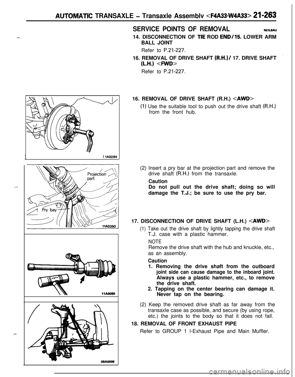
SERVICE POINTS OF REMOVALNZlL8AU14. DISCONNECTION OF
TIE ROD END/15 LOWER ARM
BALL JOINT
Refer to
P.21-227.16. REMOVAL OF DRIVE SHAFT
(R.H.)/ 17. DRIVE SHAFT
(L.H.)
P.21-227.16. REMOVAL OF DRIVE SHAFT (R.H.)
(1) Use the suitable tool to push out the drive shaft (R.H.]from the front hub.
I1 lA0288(2) Insert a pry bar at the projection part and remove the
drive shaft
(R.H.) from the transaxle.
Caution
Do not pull out the drive shaft; doing so will
damage the T.J.; be sure to use the pry bar.
17. DISCONNECTION OF DRIVE SHAFT (L.H.)
(1) Take out the drive shaft by lightly tapping the drive shaftT.J. case with a plastic hammer.
NOTERemove the drive shaft with the hub and knuckle, etc.,
as an assembly.
Caution
1. Removing the drive shaft from the outboard
joint side can cause damage to the inboard joint.Always use a plastic hammer, etc., to remove
the drive shaft.
2. Tapping on the center bearing can damage it.
Never tap on the bearing.
(2) Keep the removed drive shaft as far away from the
transaxle case as possible, and secure (by using rope,
etc.) the joints to the body so that it does not fall.
18. REMOVAL OF FRONT EXHAUST PIPE
Refer to GROUP 1 l-Exhaust Pipe and Main Muffler.
Page 1014 of 1216
21-320AUTOMATIC TRANSAXLE - Differential
TFA0231
Pinion, shaftPinion gear/
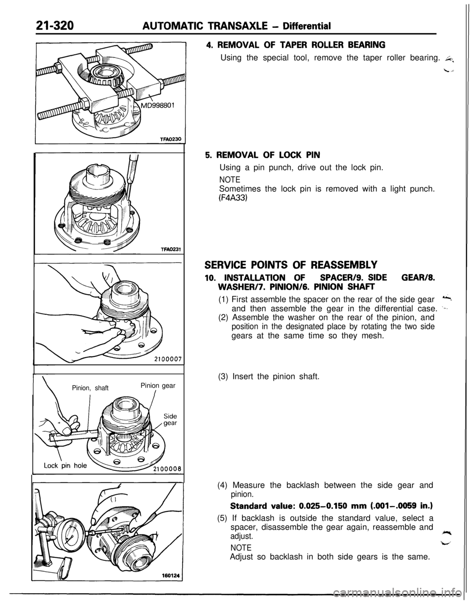
4. REMOVAL OF TAPER ROLLER BEARINGUsing the special tool, remove the taper roller bearing.
L+
5. REMOVAL OF LOCK PINUsing a pin punch, drive out the lock pin.
NOTESometimes the lock pin is removed with a light punch.
(F4A33)
SERVICE POINTS OF REASSEMBLY
10. INSTALLATION OFSPACER/S. SIDEGEAR/8.WASHERI7.
PINION/G. PINION SHAFT(1) First assemble the spacer on the rear of the side gear
&aand then assemble the gear in the differential case.
.--(2) Assemble the washer on the rear of the pinion, and
position in the designated place by rotating the two sidegears at the same time so they mesh.
(3) Insert the pinion shaft.
(4) Measure the backlash between the side gear and
pinion.Standard value:
0.025-0.150 mm (.OOl-.0059 in.)(5) If backlash is outside the standard value, select a
spacer, disassemble the gear again, reassemble and
adjust.
NOTELd
Adjust so backlash in both side gears is the same.
Page 1044 of 1216
22-6WHEELS AND TIRES - Wheel and Tire
INSTRUCTIONS FOR ALUMINUM TYPE
WHEELSUzzGfM
1. Aluminum is vulnerable to alkalies. If a vehicle
washing detergent has been used, or salt from
sea water or road chemicals has adhered, washthe vehicle as soon as possible. After washing
the vehicle, apply body or wheel wax to the
aluminum type wheels to prevent corrosion.
2. When cleaning the vehicle with steam, do not
direct steam onto the aluminum type wheels.
When tightening nuts for aluminum type
wheels, particularly observe the following:
(1) Clean the hub surface of aluminum type
wheels.(2) After finger-tightening wheel nuts, tighten
them to specifications.
(3) Do not use an impact wrench or push the
wrench by foot to tighten the wheel nuts.
(4) Do not apply oil to the threaded portions.
INSTRUCTIONS FOR TIRE CHAINS AND
SNOW TIRESNZZGGAA
1.Use tire chains only on front wheels. Do not usetire chains on rear wheels.
2. When using snow tires, use them on all four
wheels for maneuverability and safety.
INSTRUCTIONS FOR COMPACT SPARE
TIRE;c.1. The compact spare tire is designed to. save
space in the luggage compartment, and its
L’lighter weight makes it easier to use if a fiat tire
occurs.
2.The following instructions for the compact sparetire should be observed.
(1) Check the inflation pressure after installing
the spare, and adjust to the specified pres-
sure.(2) Avoid driving through automatic car washes
and over obstacles that could possibly dam-
age the vehicle’s undercarriage. Because
the tire is smaller than the original tire, car
ground clearance is slightly reduced.
(3) The compact spare tire should not be used
on any other wheels, nor should standard
tires, snow tires, wheel covers or trim rings
be used with the compact spare wheel. If
such use is attempted, damage to these
items or other vehicle components may
occur.
Page 1058 of 1216
23-14BODY - Troubleshooting
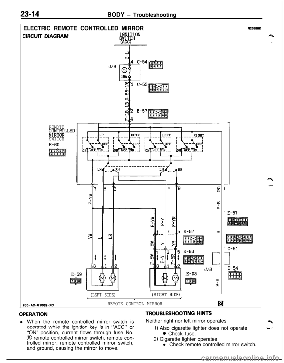
ELECTRIC REMOTE CONTROLLED MIRROR
CIRCUIT DIAGRAM
REMOTE&;;NT;LLED
SWITCH
MS-AC-UlSW-NC
L\/\I7
F
cl,,C
F
#
E-59
IpJJ%J
\/
3‘9g
4t
5
IL
;,,5 E-57m.--
!3
E-63
[z
J/BE-03
II
(LEFT SIDE)(RIGHT SIDE)LJt
REMOTE CONTROL MIRROR
1
-
i'
E-57
N23EBBD
OPERATIONl When the remote controlled mirror switch is
operated while the ignition key is in “ACC” or“ON” position, current flows through fuse No.@ remote controlled mirror switch, remote
con-trolled mirror, remote controlled mirror switch,
and ground, causing the mirror to move.
TROUBLESHOOTING HINTSNeither right nor left mirror operates
1) Also cigarette lighter does not operate0 Check fuse.
2) Cigarette lighter operates
l Check remote controlled mirror switch.
Page 1060 of 1216
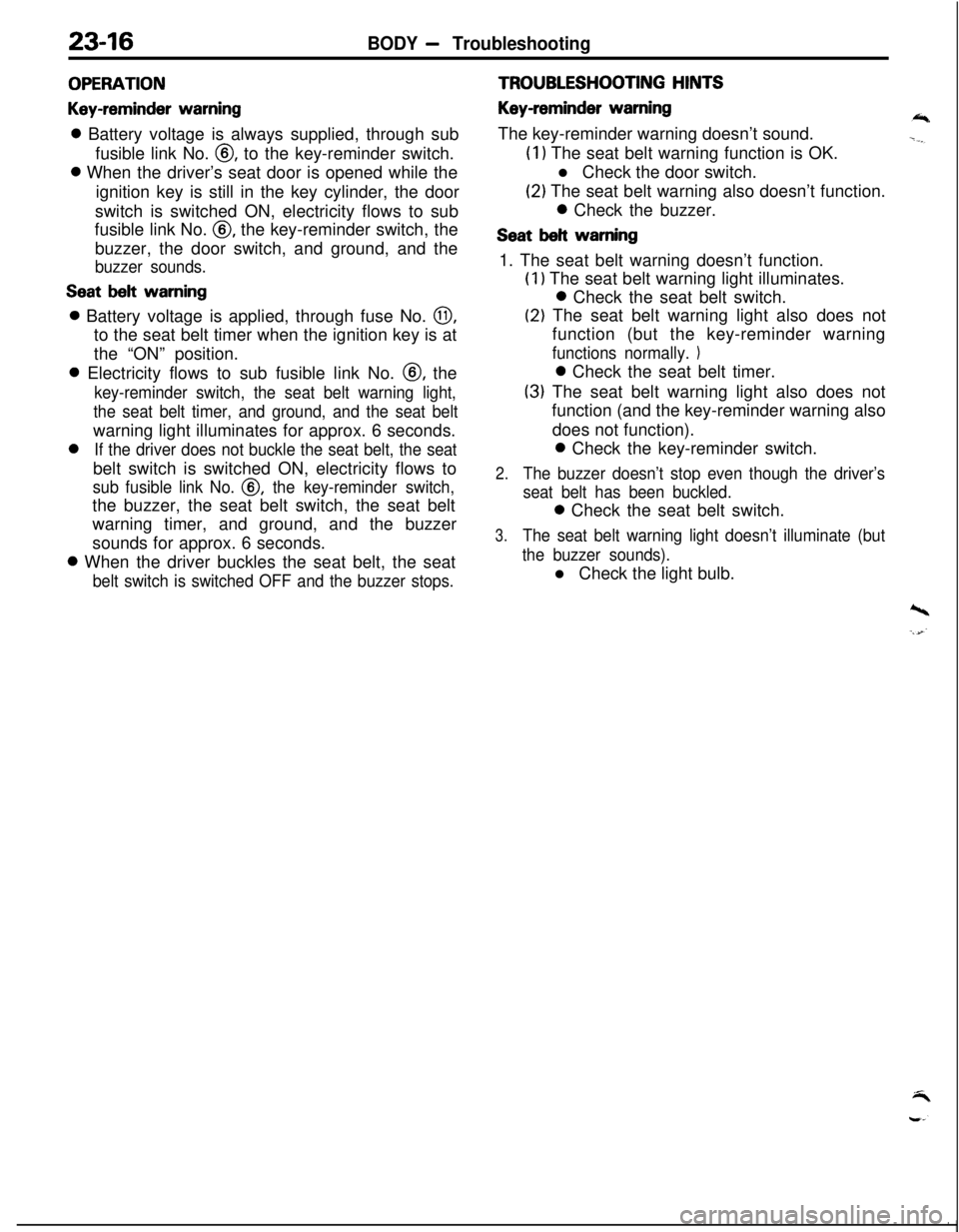
23-16BODY - Troubleshooting
OPERATION
Key-reminder warning0 Battery voltage is always supplied, through sub
fusible link No.
@, to the key-reminder switch.0 When the driver’s seat door is opened while the
ignition key is still in the key cylinder, the door
switch is switched ON, electricity flows to sub
fusible link No.
0, the key-reminder switch, the
buzzer, the door switch, and ground, and the
buzzer sounds.
Seat belt warning0 Battery voltage is applied, through fuse No.
0,to the seat belt timer when the ignition key is at
the “ON” position.0 Electricity flows to sub fusible link No. @, the
key-reminder switch, the seat belt warning light,
the seat belt timer, and ground, and the seat beltwarning light illuminates for approx. 6 seconds.0
If the driver does not buckle the seat belt, the seatbelt switch is switched ON, electricity flows to
sub fusible link No. @, the key-reminder switch,the buzzer, the seat belt switch, the seat belt
warning timer, and ground, and the buzzer
sounds for approx. 6 seconds.0 When the driver buckles the seat belt, the seat
belt switch is switched OFF and the buzzer stops.
TROUBLESHOOTING HINTS
Key-reminder warningThe key-reminder warning doesn’t sound.
(1) The seat belt warning function is OK.
l Check the door switch.
(2) The seat belt warning also doesn’t function.0 Check the buzzer.
Seat belt warning1. The seat belt warning doesn’t function.
(1) The seat belt warning light illuminates.0 Check the seat belt switch.
(2) The seat belt warning light also does not
function (but the key-reminder warning
functions normally. 10 Check the seat belt timer.
(3) The seat belt warning light also does not
function (and the key-reminder warning also
does not function).0 Check the key-reminder switch.
2.The buzzer doesn’t stop even though the driver’s
seat belt has been buckled.0 Check the seat belt switch.
3.The seat belt warning light doesn’t illuminate (but
the buzzer sounds).l Check the light bulb.
’ I
Page 1063 of 1216
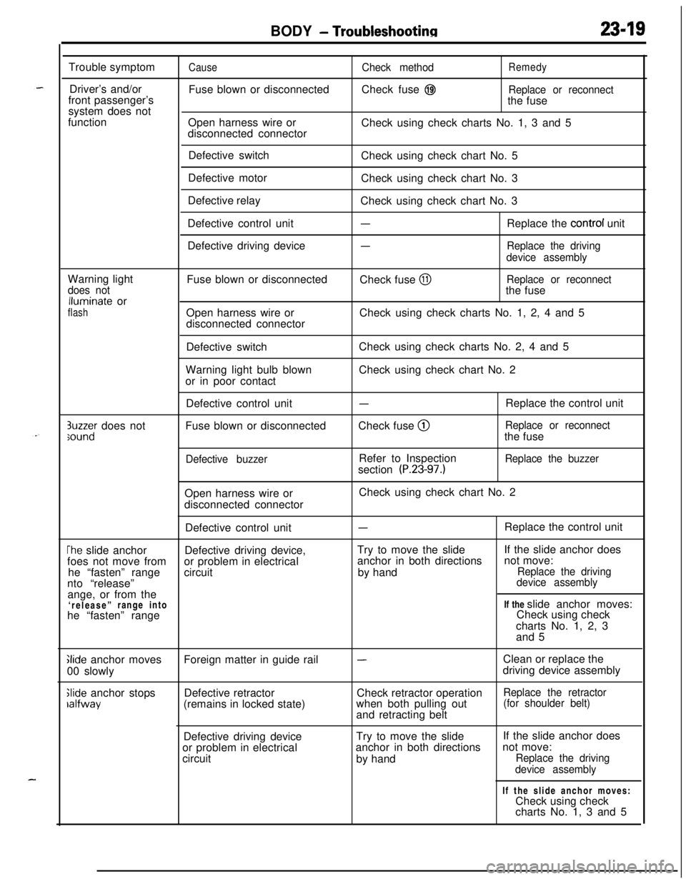
BODY - Troubleshootinn2349Trouble symptom
Driver’s and/or
front passenger’s
system does not
function
CauseFuse blown or disconnected
Open harness wire or
disconnected connectorCheck methodRemedyCheck fuse
@IReplace or reconnectthe fuse
Check using check charts No. 1, 3 and 5
Defective switch
Defective motor
Defective relay
Defective control unit
Defective driving deviceCheck using check chart No. 5
Check using check chart No. 3
Check using check chart No. 3
-Replace the control unit
-Replace the driving
device assemblyWarning light
does notlluminate or
flashFuse blown or disconnected
Open harness wire or
disconnected connectorCheck fuse
@IReplace or reconnectthe fuse
Check using check charts No. 1, 2, 4 and 5
Defective switch
Warning light bulb blown
or in poor contactCheck using check charts No. 2, 4 and 5
Check using check chart No. 2
3uzzer does notsoundDefective control unit
Fuse blown or disconnected
Defective buzzer
-Check fuse @
Refer to Inspection
section
(P.23-97.)Replace the control unit
Replace or reconnectthe fuse
Replace the buzzerOpen harness wire or
disconnected connectorCheck using check chart No. 2
Defective control unit
-Replace the control unit
The slide anchorDefective driving device,Try to move the slideIf the slide anchor does
foes not move fromor problem in electricalanchor in both directionsnot move:
he “fasten” rangecircuitby hand
Replace the drivingnto “release”device assemblyange, or from the
‘release”range intoIf the slide anchor moves:
he “fasten” rangeCheck using check
charts No. 1, 2, 3
and 5
Glide anchor moves
00 slowly
Slide anchor stopsralfwayForeign matter in guide rail
Defective retractor
(remains in locked state)
-Clean or replace the
driving device assembly
Check retractor operation
Replace the retractorwhen both pulling out(for shoulder belt)and retracting belt
Defective driving deviceTry to move the slide
or problem in electricalanchor in both directions
circuit
by handIf the slide anchor does
not move:
Replace the driving
device assemblyIf the slide anchor moves:
Check using check
charts No. 1, 3 and 5