light MITSUBISHI ECLIPSE 1991 Owners Manual
[x] Cancel search | Manufacturer: MITSUBISHI, Model Year: 1991, Model line: ECLIPSE, Model: MITSUBISHI ECLIPSE 1991Pages: 1216, PDF Size: 67.42 MB
Page 721 of 1216
MANUAL TRANSAXLE
206001E
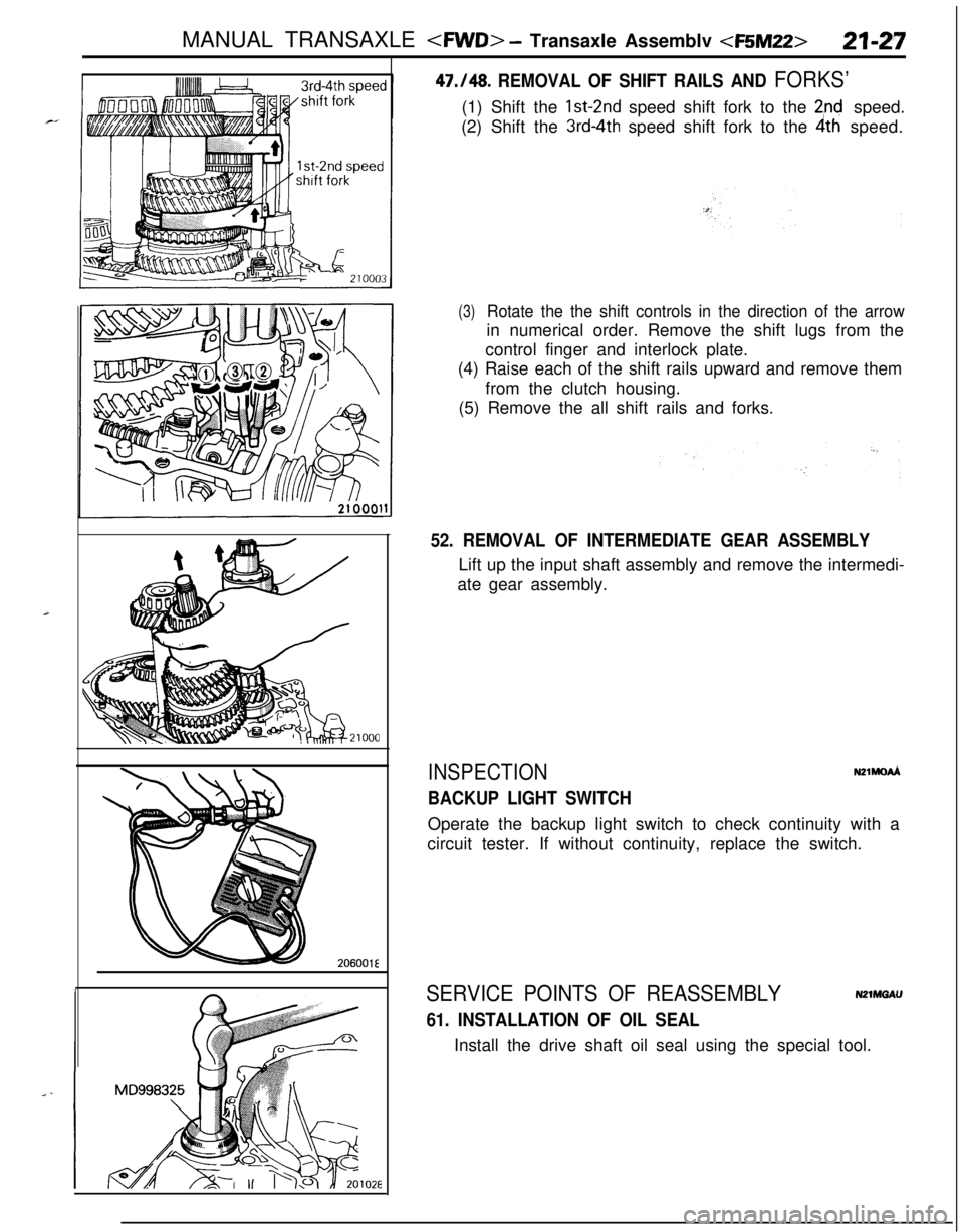
47./48. REMOVAL OF SHIFT RAILS AND FORKS’(1) Shift the Ist-2nd speed shift fork to the
2nd speed.
(2) Shift the
3rd~4th speed shift fork to the 4th speed.
(3)Rotate the the shift controls in the direction of the arrowin numerical order. Remove the shift lugs from the
control finger and interlock plate.
(4) Raise each of the shift rails upward and remove them
from the clutch housing.
(5) Remove the all shift rails and forks.
52. REMOVAL OF INTERMEDIATE GEAR ASSEMBLYLift up the input shaft assembly and remove the intermedi-
ate gear assembly.
INSPECTION
BACKUP LIGHT SWITCH
N21MOdOperate the backup light switch to check continuity with a
circuit tester. If without continuity, replace the switch.
SERVICE POINTS OF REASSEMBLYN2mnGAU
61. INSTALLATION OF OIL SEALInstall the drive shaft oil seal using the special tool.
Page 727 of 1216
MANUAL TRANSAXLE
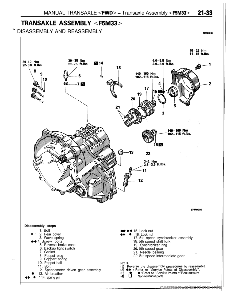
TRANSAXLE ASSEMBLY
3 DISASSEMBLY AND REASSEMBLYNZlME-6
--42 Nm
-30
ft.lbs.
\8I Q
30-35Nm
22-25ft.lbs.ml4
ff3d6 i
18
4.0-5.5Nm2.9-3.9ft.lbs.
-n
140-160 Nm102-115ft.&s.
3-5 Nm
16-22 Nm11-15 ft.lbs.1Disassembly steps
‘I. Bolt
l *2. Rear cover3.Wave springe4 4. Screw bolts5. Reverse brake cone6. Backup light switch
7.Gasket
8.Poppet plug9.Poppert spring
10.Poppet ball11.Bolt
12. Speedometer driven gear assembly
l 13. Air breather
4* l * 14. Spring pin
,I
2
TFMool6
4+ e4 15. Lock nut+e l 16. Lock nut17. 5th speed synchronizer assembly18. 5th speed shift fork19. Synchronizer ring20. 5th speed gear21. Needle bearing22.
5th speed intermediate gear.’
$?everse the disassembly procedures to reassemble.(2) +e : Refer to “Service Points of Disassembly:.(3) l C : Refer to “Service Points of Reassembly(4) q : Non-reusable parts
Page 731 of 1216
MANUAL TRANSAXLE
18
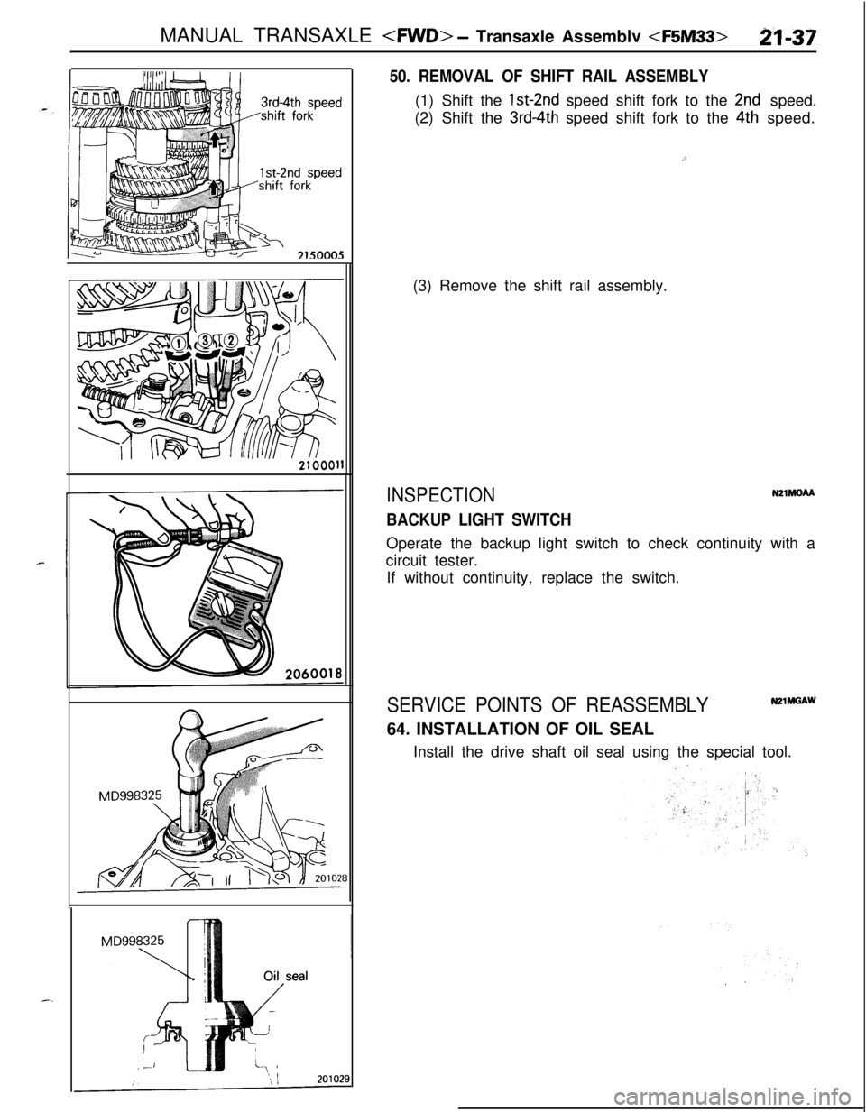
50. REMOVAL OF SHIFT RAIL ASSEMBLY(1) Shift the
1st~2nd speed shift fork to the 2nd speed.
(2) Shift the
3rd4th speed shift fork to the 4th speed.
.”(3) Remove the shift rail assembly.
INSPECTIONNZlMOM
BACKUP LIGHT SWITCHOperate the backup light switch to check continuity with a
circuit tester.
If without continuity, replace the switch.
SERVICE POINTS OF REASSEMBLY64. INSTALLATION OF OIL SEAL
Install the drive shaft oil seal using the special tool.
:
Page 769 of 1216
MANUAL TRANSAXLE
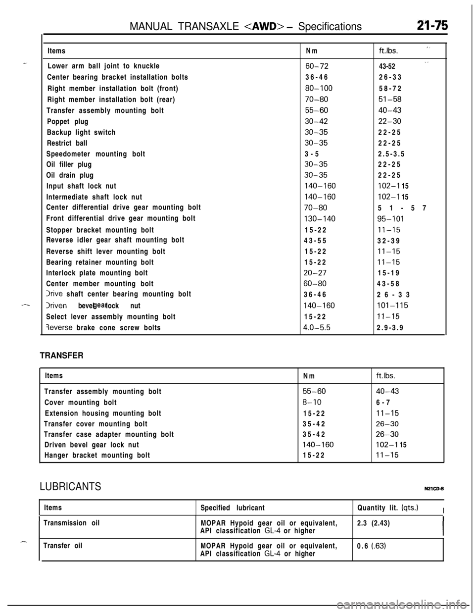
Lower arm ball joint to knuckle
Center bearing bracket installation bolts
Right member installation bolt (front)
Right member installation bolt (rear)
Transfer assembly mounting bolt
Poppet plug
Backup light switch
Restrict ball
Speedometer mounting bolt
Oil filler plug
Oil drain plug
Input shaft lock nut
Intermediate shaft lock nut
Center differential drive gear mounting bolt
Front differential drive gear mounting bolt
Stopper bracket mounting bolt
Reverse idler gear shaft mounting bolt
Reverse shift lever mounting bolt
Bearing retainer mounting bolt
Interlock plate mounting bolt
Center member mounting bolt
Irive shaft center bearing mounting bolt
Iriven bevel lock nutgear
Select lever assembly mounting bolt
3everse brake cone screw boltsNm
ft.Ibs. ”
60-7243-52 “
36-4626-33
80-10058-72
70-8051-58
55-6040-43
30-4222-30
30-3522-25
30-3522-25
3-52.5-3.5
30-3522-25
30-3522-25
140-160102-I 15
140-160102-I 15
70-8051-57
130-14095-10115-22
11-1543-55
32-39
15-22
11-1515-22
11-15
20-2715-19
60-8043-58
36-46
26-33
140-160101-11515-22
11-15
4.0-5.52.9-3.9
TRANSFERItems
Transfer assembly mounting bolt
Cover mounting bolt
Extension housing mounting bolt
Transfer cover mounting bolt
Transfer case adapter mounting bolt
Driven bevel gear lock nut
Hanger bracket mounting boltNm
ft.lbs.
55-6040-43
8-106-7
15-22
II-1535-42
26-3035-42
26-30
140-160102-I 15
15-22
11-15
LUBRICANTSN21CD.BItems
Specified lubricantQuantity lit. (qts.)
I
ITransmission oil
MOPAR Hypoid gear oil or equivalent,2.3 (2.43)
API classification GL-4 or higherITransfer oil
MOPAR Hypoid gear oil or equivalent,
API classification
GL-4 or higher0.6 (.63)
Page 776 of 1216
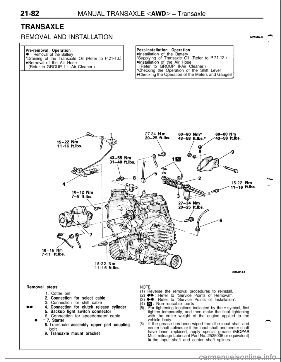
21-82MANUAL TRANSAXLE
TRANSAXLE
REMOVAL AND INSTALLATION
Pre-removal Operationl Removal of the Battery*Draining of the Transaxle Oil (Refer to P.Zl-13.)
@Removal of the Air Hose
(Refer to GROUP 11 -Air Cleaner.)IO-1
7-1111-16
ftlbs.
Post-installation Operation@Installation of the Battery
*Supplying of Transaxle Oil (Refer to P.21-13.)*Installation of the Air Hose
(Refer to GROUP II-Air Cleaner.)
*Checking the Operation of the Shift Lever
@Checking the Operation of the Meters and Gauges
27-34 Nm
60-60 Nm*60-80 Nm20-25 ft.lbs.
\
43-58/t.,b~43-58 ft.lbs.
15-22
6 Nm
ftlbs.
15-22 Nm
vt11-16
ft.lbs.Removal steps
1. Cotter pin
2. Connection for select cable
3. Connection for shift cable
*I)4. Connection for clutch release cylinder
5. Backup light switch connector
6. Connection for speedometer cable
l * 7. Starter
8.
A;;saxle assembly upper part coupling
9. Transaxle mount bracket
NZlMA-B -
,“rr,s.
09AOl44
NOTE(1) Reverse the removal procedures to reinstall.
(2)
+e : Refer to “Service Points of Removal”.
(3) I)+ : Refer to “Service Points of Installation”.
(4) m : Non-reusable parts(5)For tightening locations indicated by the * symbol, first
tighten temporarily, and then make the final tightening
with the entire weight of the engine applied to the
(6)vehicle body.
If the grease has been wiped from the input shaft and
center shaft splines or if the input shaft and center shaft
have been replaced, apply special grease
(MOPARMulti-mileage Lubricant Part No. 2525035 or equivalent)
to the input shaft and center shaft splines.
Page 778 of 1216
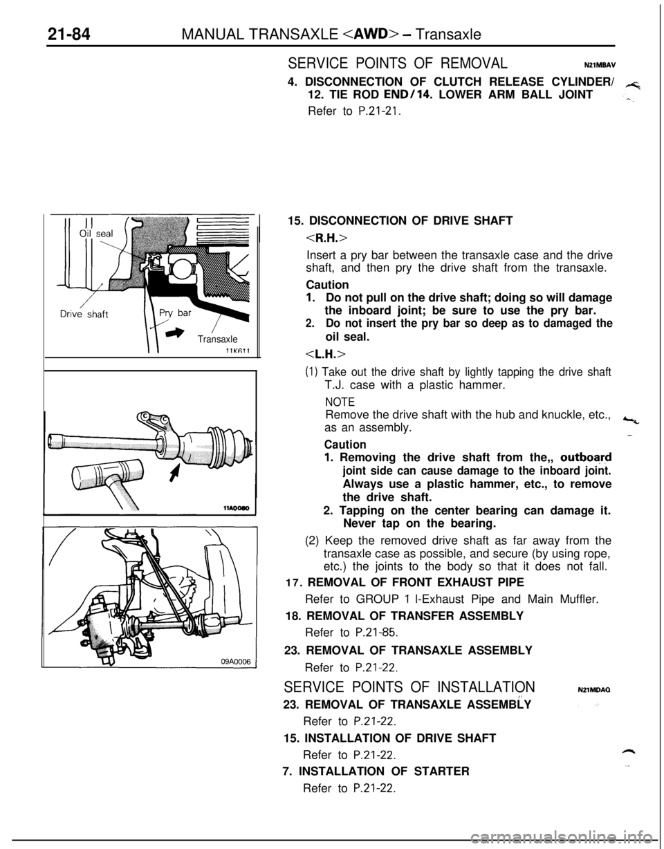
21-84MANUAL TRANSAXLE
r) ’TransaxlellKfil1
SERVICE POINTS OF REMOVALN21MBAV4. DISCONNECTION OF CLUTCH RELEASE CYLINDER/
12. TIE ROD
END/l4. LOWER ARM BALL JOINT
Refer to
P.21-21.15. DISCONNECTION OF DRIVE SHAFT
shaft, and then pry the drive shaft from the transaxle.
Caution
1.Do not pull on the drive shaft; doing so will damage
the inboard joint; be sure to use the pry bar.
2.Do not insert the pry bar so deep as to damaged theoil seal.
(1) Take out the drive shaft by lightly tapping the drive shaftT.J. case with a plastic hammer.
NOTERemove the drive shaft with the hub and knuckle, etc.,
as an assembly.
Caution
1. Removing the drive shaft from the,, outboa,rd
joint side can cause damage to the inboard joint.Always use a plastic hammer, etc., to remove
the drive shaft.
2. Tapping on the center bearing can damage it.
Never tap on the bearing.
(2) Keep the removed drive shaft as far away from the
transaxle case as possible, and secure (by using rope,
etc.) the joints to the body so that it does not fall.
17. REMOVAL OF FRONT EXHAUST PIPE
Refer to GROUP
1 l-Exhaust Pipe and Main Muffler.
18. REMOVAL OF TRANSFER ASSEMBLY
Refer to
P.21-85.23. REMOVAL OF TRANSAXLE ASSEMBLY
Refer to
P.21-22.
SERVICE POINTS OF INSTALLATION!’23. REMOVAL OF TRANSAXLE ASSEMBLY
Refer to
P.21-22.15. INSTALLATION OF DRIVE SHAFT
Refer to
P.21-22.7. INSTALLATION OF STARTER
Refer to
P.21-22.
NZlMDAQ
Page 780 of 1216
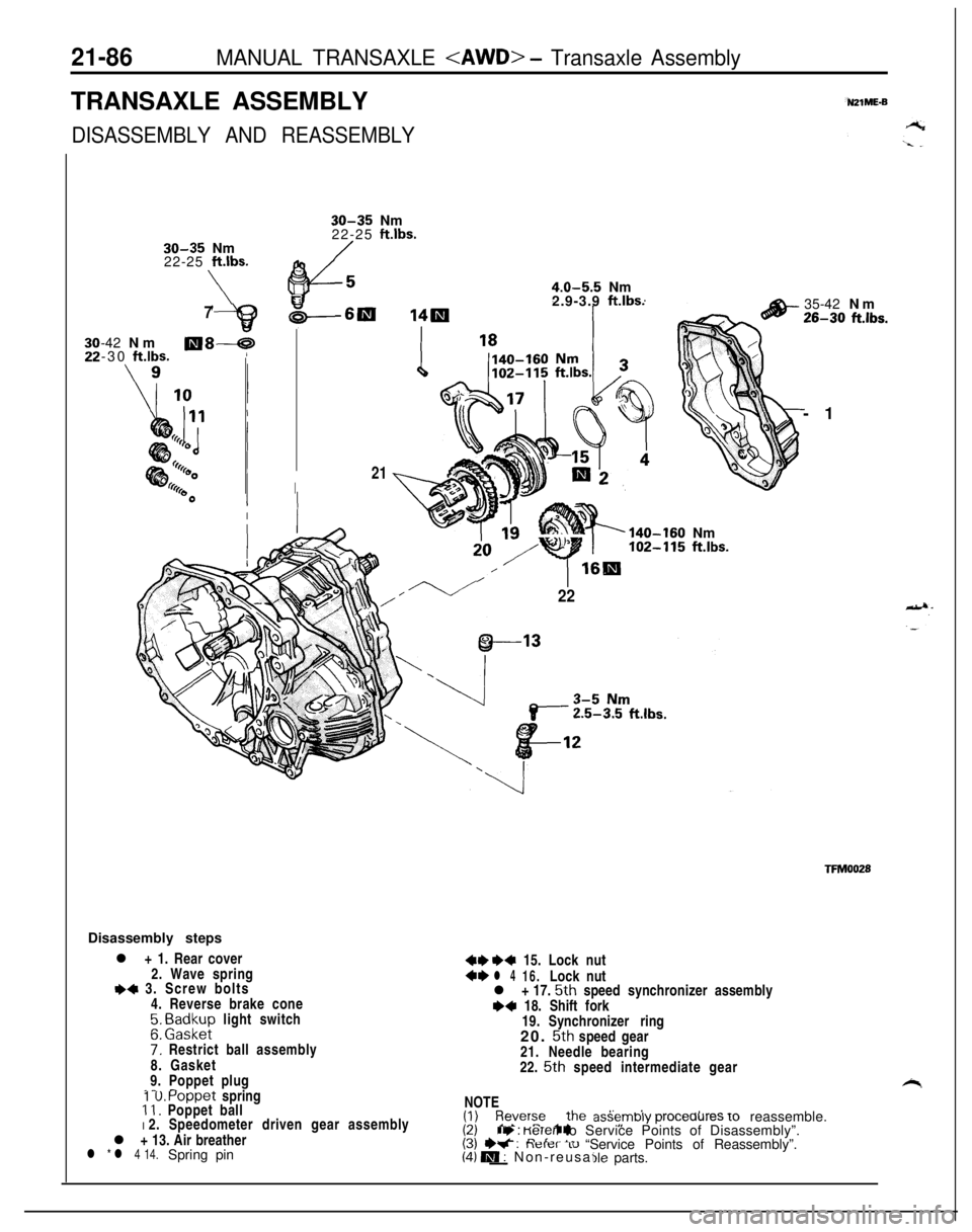
21-86MANUAL TRANSAXLE
DISASSEMBLY AND REASSEMBLY
30-35 Nm
22-25 ft.lbs.
\
30-35 Nm
22-25 Wbs.
4.0-5.5 Nm\62.9-3.9 ft.lbs.7-42 Nm
-30
ft.lbs.llI8-59
I21IDisassembly steps
l + 1. Rear cover
2. Wave spring
I)+ 3. Screw bolts
4. Reverse brake cone
;. E;zk;p light switch
7: Restrict ball assembly
8. Gasket
9. Poppet plug
.- ^1 U. Poppet spring11. Poppet ball
I 2. Speedometer driven gear assembly
l + 13. Air breather
l * l 4 14.Spring pin
140-160 Nm
w ”Y
102-115 ft.lbs.
16Bl/
22
++ I)+ 15. Lock nut+el 416.Lock nut
l + 17. 5th speed synchronizer assembly~~ 18. Shift fork
19.Synchronizer ring
20.
5th speed gear
21.Needle bearing
22.
5th speed intermediate gear35-42 Nm
26-30 ft.lbs.-1
TFMOOZSNOTE
(1) Revers_e the di?: ’(2) +-(3) +v : neler 10(4) IW : Non-reusat-yle parts.assembly
proceaures 10 reassemble.ry : KeTer to Service Points of Disassembly”.“-I-- I- “Service Points of Reassembly”.
’
i
Page 793 of 1216
MANUAL TRANSAXLE
sealant
TFM0041
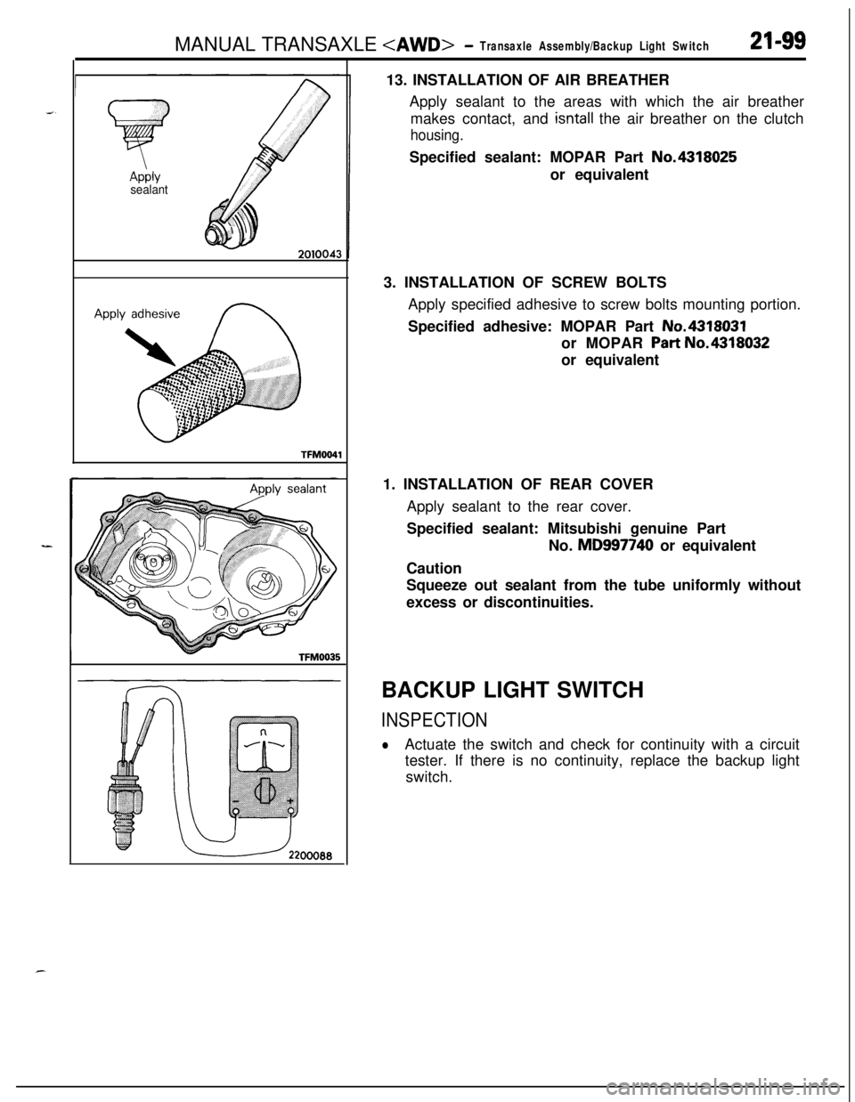
TFM003513. INSTALLATION OF AIR BREATHER
Apply sealant to the areas with which the air breather
makes contact, and
isntall the air breather on the clutch
housing.Specified sealant: MOPAR Part No.4318025
or equivalent
3. INSTALLATION OF SCREW BOLTS
Apply specified adhesive to screw bolts mounting portion.
Specified adhesive: MOPAR Part No.4318031
or MOPAR
Part No.4318032
or equivalent
1. INSTALLATION OF REAR COVER
Apply sealant to the rear cover.
Specified sealant: Mitsubishi genuine Part
No. MD997740 or equivalent
Caution
Squeeze out sealant from the tube uniformly without
excess or discontinuities.
BACKUP LIGHT SWITCH
INSPECTION
lActuate the switch and check for continuity with a circuit
tester. If there is no continuity, replace the backup light
switch.
Page 798 of 1216
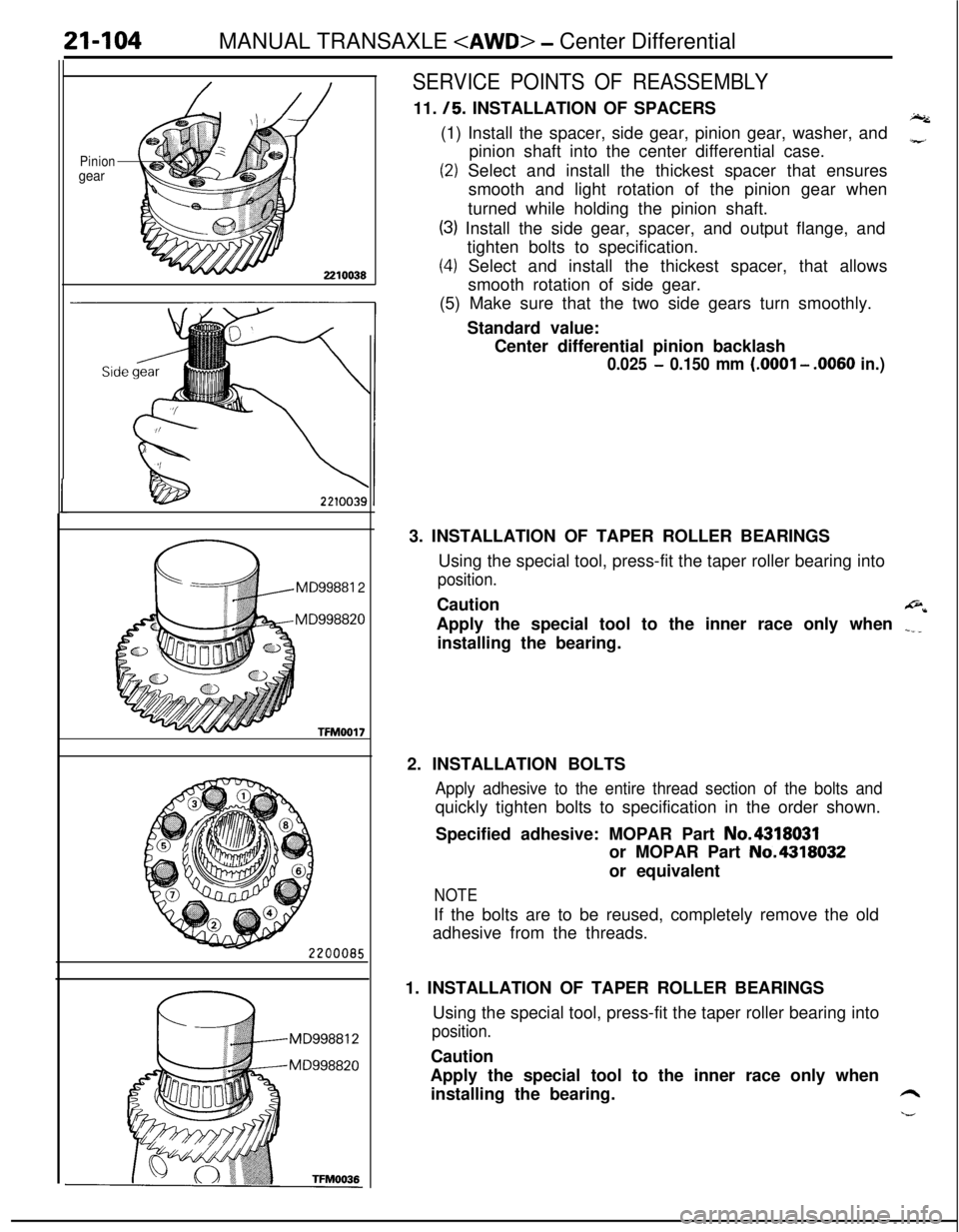
21-104MANUAL TRANSAXLE
Piniongear
MD99881 2
MD998820
TFM0017
SERVICE POINTS OF REASSEMBLY11.
/5. INSTALLATION OF SPACERSI.(1) Install the spacer, side gear, pinion gear, washer, and
pinion shaft into the center differential case.
z
(2) Select and install the thickest spacer that ensures
smooth and light rotation of the pinion gear when
turned while holding the pinion shaft.
(3) Install the side gear, spacer, and output flange, and
tighten bolts to specification.
(4) Select and install the thickest spacer, that allows
smooth rotation of side gear.
(5) Make sure that the two side gears turn smoothly.
Standard value:
Center differential pinion backlash
0.025 - 0.150 mm (.OOOl - .0060 in.)3. INSTALLATION OF TAPER ROLLER BEARINGS
Using the special tool, press-fit the taper roller bearing into
position.Caution
@*Apply the special tool to the inner race only when
.___installing the bearing.
2. INSTALLATION BOLTS
Apply adhesive to the entire thread section of the bolts andquickly tighten bolts to specification in the order shown.
Specified adhesive: MOPAR Part No.4318031
or MOPAR Part No.4318032
or equivalent
NOTEIf the bolts are to be reused, completely remove the old
adhesive from the threads.
1. INSTALLATION OF TAPER ROLLER BEARINGS
Using the special tool, press-fit the taper roller bearing into
position.Caution
Apply the special tool to the inner race only when
installing the bearing.
6
h--
Page 877 of 1216
AUTOMATIC TRANSAXLE - Troubleshooting214%3
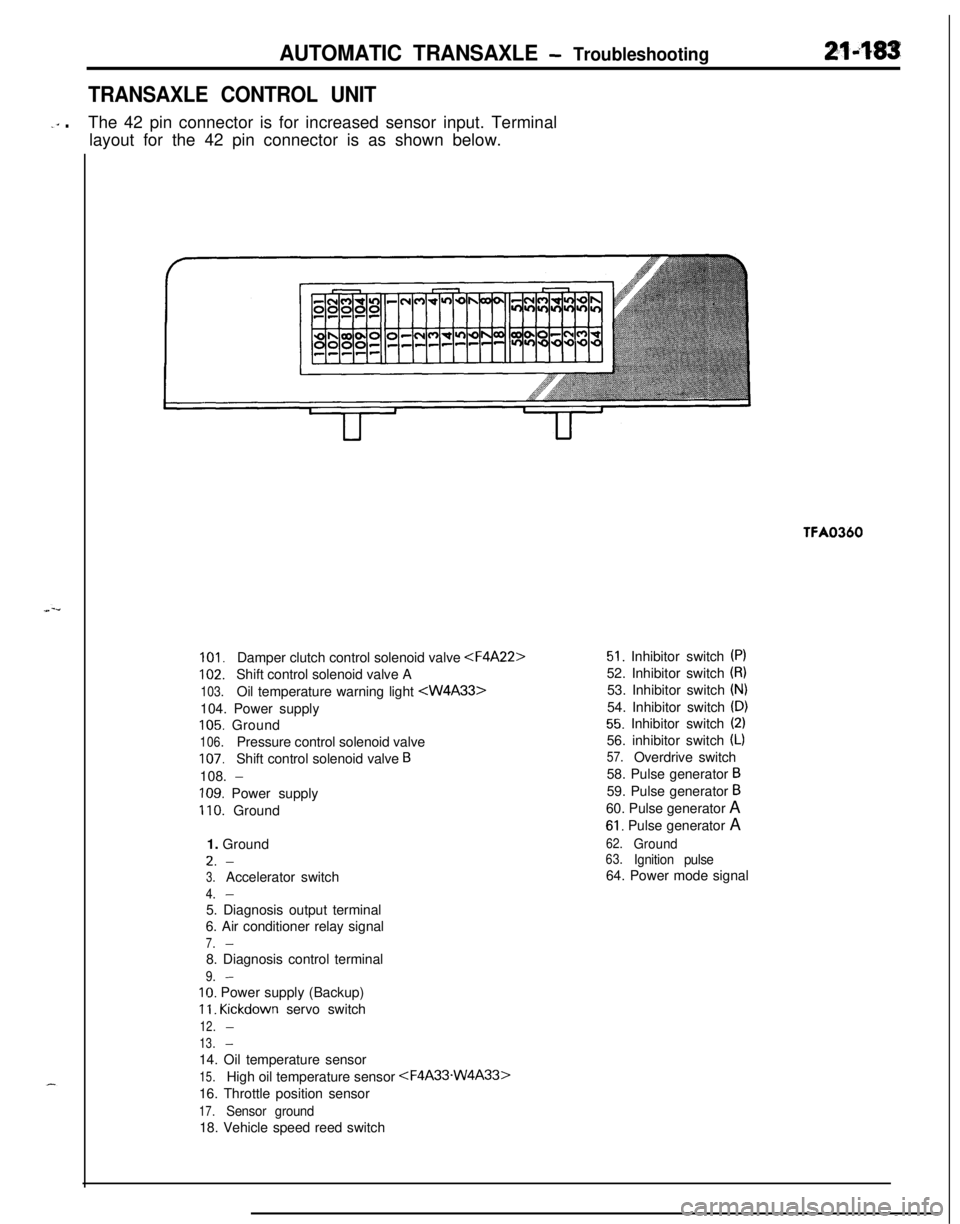
TRANSAXLE CONTROL UNIT
-‘” .The 42 pin connector is for increased sensor input. Terminal
layout for the 42 pin connector is as shown below.TFA0360
101.Damper clutch control solenoid valve
102.Shift control solenoid valve A
103.Oil temperature warning light
105. Ground
106.Pressure control solenoid valve
107.Shift control solenoid valve B108.
-
109. Power supply
110. Ground
1. GroundL.
-
3.Accelerator switch
4.-5. Diagnosis output terminal
6. Air conditioner relay signal
7.-8. Diagnosis control terminal
9.-
IO. Power supply (Backup)
11. Kickdown servo switch
12.-
13.-14. Oil temperature sensor
15.High oil temperature sensor
16. Throttle position sensor
17.Sensor ground18. Vehicle speed reed switch
51. Inhibitor switch (PI52. Inhibitor switch
(8)53. Inhibitor switch
(N)54. Inhibitor switch
(D)
55. Inhibitor switch (2)56. inhibitor switch
(L)
57.Overdrive switch
58. Pulse generator
B59. Pulse generator
B60. Pulse generator A
61. Pulse generator A
62.Ground63.Ignition pulse64. Power mode signal