light MITSUBISHI ECLIPSE 1991 Manual Online
[x] Cancel search | Manufacturer: MITSUBISHI, Model Year: 1991, Model line: ECLIPSE, Model: MITSUBISHI ECLIPSE 1991Pages: 1216, PDF Size: 67.42 MB
Page 623 of 1216
REAR SUSPENSION
Inut
-
-Spindle
14AO419
SERVICE POINTS OF REMOVALNliP9AG
1.REMOVAL OF REAR SPEED SENSOR
5-Wheel Speed Sensor.
4. REMOVAL OF CALIPER ASSEMBLYRemove the caliper assembly and suspend it with a piece
of wire.
9. REMOVAL OF REAR HUB BEARING UNIT
NOTERear hub bearing unit cannot be disassemble.
12. REMOVAL OF SHOCK ABSORBER LOWER MOUNTING
BOLT/lB. TRAILING ARM MOUNTING BOLT/ 14.
TORSION AXLE AND ARM ASSEMBLY
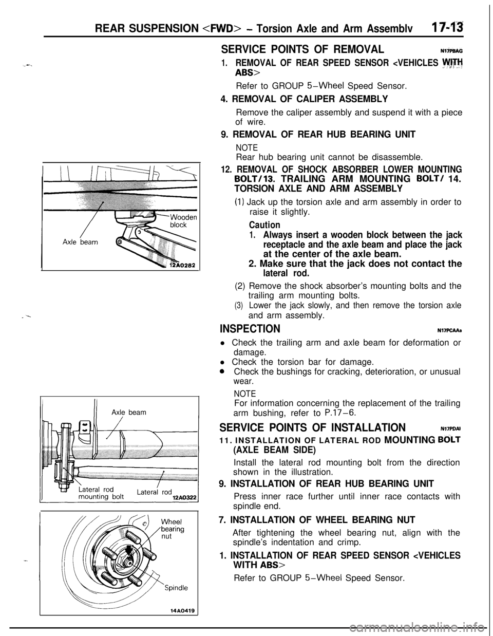
(1) Jack up the torsion axle and arm assembly in order to
raise it slightly.
Caution
1.Always insert a wooden block between the jack
receptacle and the axle beam and place the jackat the center of the axle beam.
2. Make sure that the jack does not contact the
lateral rod.(2) Remove the shock absorber’s mounting bolts and the
trailing arm mounting bolts.
(3)Lower the jack slowly, and then remove the torsion axleand arm assembly.
INSPECTIONN17PCAAa
l Check the trailing arm and axle beam for deformation or
damage.l Check the torsion bar for damage.
0Check the bushings for cracking, deterioration, or unusual
wear.
NOTEFor information concerning the replacement of the trailing
arm bushing, refer to
P.17-6.
SERVICE POINTS OF INSTALLATIONN17PDAI
11. INSTALLATION OF LATERAL ROD MOUNTING
BdLT
(AXLE BEAM SIDE)Install the lateral rod mounting bolt from the direction
shown in the illustration.
9. INSTALLATION OF REAR HUB BEARING UNITPress inner race further until inner race contacts with
spindle end.
7. INSTALLATION OF WHEEL BEARING NUTAfter tightening the wheel bearing nut, align with the
spindle’s indentation and crimp.
1. INSTALLATION OF REAR SPEED SENSOR
5-Wheel Speed Sensor.
Page 633 of 1216
REAR SUSPENSION
14AO520
12AOlOQ
SERVICE POINTS OF REMOVALN17GQAOa4. REMOVAL OF CALIPER ASSEMBLY
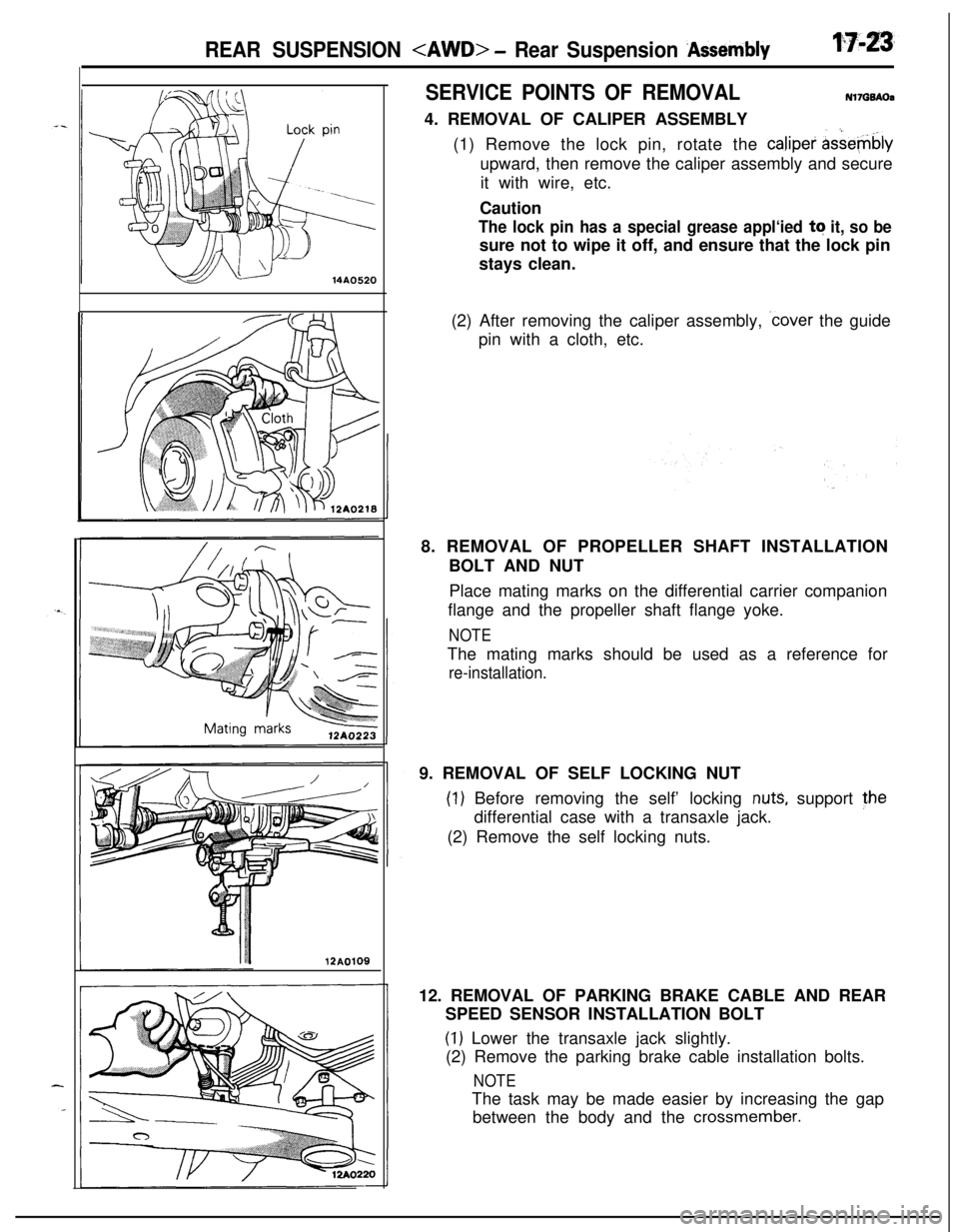
(1) Remove the lock pin, rotate the calipei
&&e-@blyupward, then remove the caliper assembly and secure
it with wire, etc.
Caution
The lock pin has a special grease appl‘ied tq it, so besure not to wipe it off, and ensure that the lock pin
stays clean.
(2) After removing the caliper assembly,
.cover the guide
pin with a cloth, etc.
8. REMOVAL OF PROPELLER SHAFT INSTALLATION
BOLT AND NUT
Place mating marks on the differential carrier companion
flange and the propeller shaft flange yoke.
NOTEThe mating marks should be used as a reference for
re-installation.9. REMOVAL OF SELF LOCKING NUT
(1) Before removing the self’ locking nuts, support the
differential case with a transaxle jack.
(2) Remove the self locking nuts.
12. REMOVAL OF PARKING BRAKE CABLE AND REAR
SPEED SENSOR INSTALLATION BOLT
(1) Lower the transaxle jack slightly.
(2) Remove the parking brake cable installation bolts.
NOTEThe task may be made easier by increasing the gap
between the body and the
crossmember.
Page 646 of 1216
17-36REAR SUSPENSION
/12AOllO
\.1210111
SERVICE POINTS OF REMOVALNl7ljMB
1. REMOVAL OFSELFLOCKINGNUT/P.CROSSMEMBER BRACKET
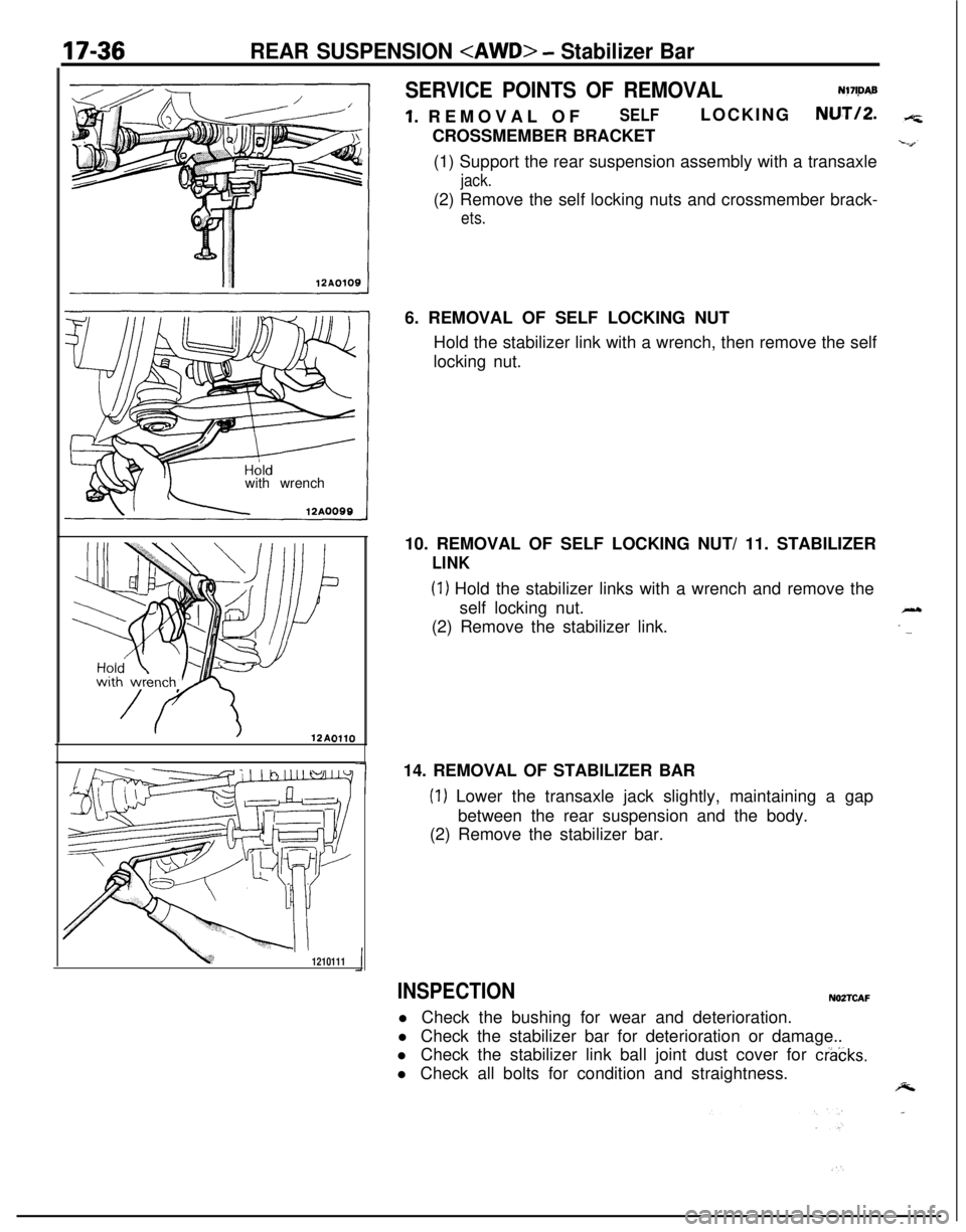
(1) Support the rear suspension assembly with a transaxle
jack.(2) Remove the self locking nuts and crossmember brack-
ets.6. REMOVAL OF SELF LOCKING NUT
Hold the stabilizer link with a wrench, then remove the self
locking nut.
10. REMOVAL OF SELF LOCKING NUT/ 11. STABILIZER
LINK
(1) Hold the stabilizer links with a wrench and remove the
self locking nut.
(2) Remove the stabilizer link.
14. REMOVAL OF STABILIZER BAR
(1) Lower the transaxle jack slightly, maintaining a gap
between the rear suspension and the body.
(2) Remove the stabilizer bar.7
INSPECTIONNOZTCAFl Check the bushing for wear and deterioration.
l Check the stabilizer bar for deterioration or damage..
l Check the stabilizer link ball joint dust cover for
cracks.l Check all bolts for condition and straightness.
Page 655 of 1216
STEERING - Special Tools/Service Adjustment Procedures
ToolNumberName1 UseI
MB991213Rack installer ’Rack installation:,.I/ ._i’, ‘,‘#
MB991317Seal ring installerCompression of the seal rings afterreplacement of the pinion seal rings13A0282
,
SERVICE ADJUSTMENT PROCEDURiS
< MANUAL STEERING >
STEERING WHEEL FREE PLAY CHECKNOSFAAE
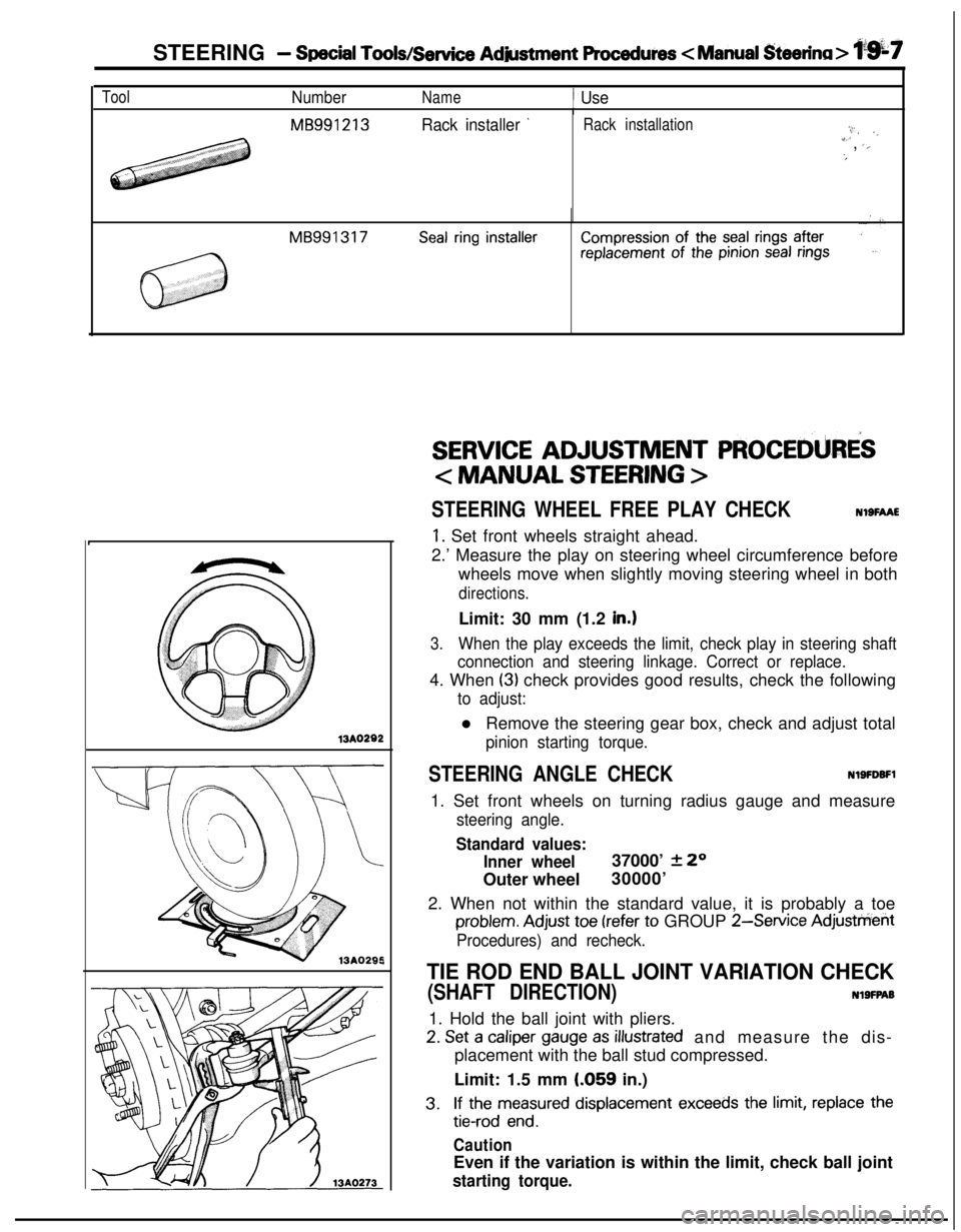
1. Set front wheels straight ahead.
2.’ Measure the play on steering wheel circumference before
wheels move when slightly moving steering wheel in both
directions.Limit: 30 mm (1.2
in.1
3.When the play exceeds the limit, check play in steering shaft
connection and steering linkage. Correct or replace.4. When
(3) check provides good results, check the following
to adjust:l Remove the steering gear box, check and adjust total
pinion starting torque.
STEERING ANGLE CHECKNlSFDBFl1. Set front wheels on turning radius gauge and measure
steering angle.
Standard values:
Inner wheel37000’
2 20
Outer wheel30000’
2. When not within the standard value, it is probably a toe
problem. Adjust toe (refer to GROUP 2-Service Adjusttierit
Procedures) and recheck.
TIE ROD END BALL JOINT VARIATION CHECK
(SHAFT DIRECTION)NlSFPAB1. Hold the ball joint with pliers.
2. Set a caliper gauge as illustrated and measure the dis-
placement with the ball stud compressed.
Limit: 1.5 mm
LO59 in.)
3.If the measured displacement exceeds the limit, replace the
tie-rod end.
CautionEven if the variation is within the limit, check ball joint
starting torque.
Page 658 of 1216
19-10STEERING - Service Adjustment Procedures c Power Steering>
r13A029213A0293
r
1
i
SERVICE ADJUSTMENT PROCEDURES
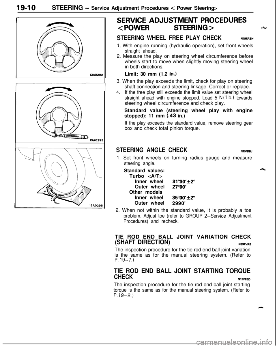
STEERING WHEEL FREE PLAY CHECKNlSFABH
1. With engine running (hydraulic operation), set front wheels
straight ahead.2. Measure the play on steering wheel circumference before
wheels start to move when slightly moving steering wheel
in both directions.
Limit: 30 mm (1.2
in.13. When the play exceeds the limit, check for play on steering
shaft connection and steering linkage. Correct or replace.
4.If the free play still exceeds the limit value set steering wheel
straight ahead with engine stopped. Load 5
N (1 lb.1 towardssteering wheel circumference and check play.
Standard value (steering wheel play with engine
stopped): 11 mm
I.43 in.)
If the play exceeds the standard value, remove steering gearbox and check total pinion torque.
STEERING ANGLE CHECKN19FDBJ1. Set front wheels on turning radius gauge and measure
steering angle.Standard values:
Turbo
Inner wheel
31”30’+2”Outer wheel
27”OOOther models
Inner wheel
35”00’_+2”Outer wheel
2990’
2. When not within the standard value, it is probably a toe
problem. Adjust toe (refer to GROUP 2-Service Adjustment
Procedures) and recheck.TIE ROD END BALL JOINT VARIATION CHECK
(SHAFT DIRECTION)N19FVA8The inspection procedure for the tie rod end ball joint variation
is the same as for the manual steering system. (Refer to
P. 19-7.)
TIE ROD END BALL JOINT STARTING TORQUE
CHECKNlSFEBDThe inspection procedure for the tie rod end ball joint starting
torque is the same as for the manual steering system. (Refer to
P.19-8.)
Page 690 of 1216
19-42STEERING - Power Steering Oil Pump
13A0279SERVICE POINTS OF DISASSEMBLY
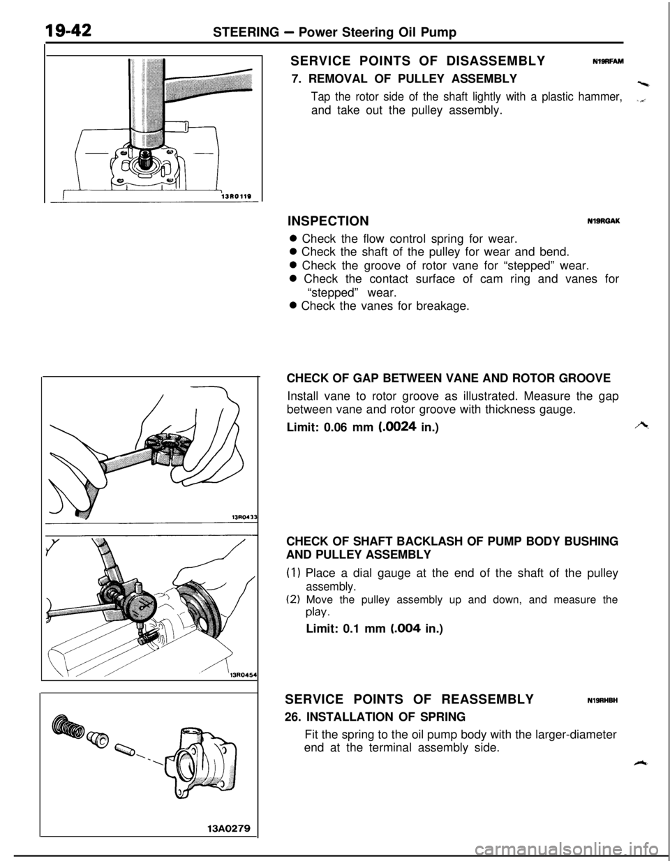
NleRFAM7. REMOVAL OF PULLEY ASSEMBLY
%
Tap the rotor side of the shaft lightly with a plastic hammer,,,~and take out the pulley assembly.
INSPECTION
NlSRGAK0 Check the flow control spring for wear.0 Check the shaft of the pulley for wear and bend.0 Check the groove of rotor vane for “stepped” wear.0 Check the contact surface of cam ring and vanes for
“stepped” wear.0 Check the vanes for breakage.
CHECK OF GAP BETWEEN VANE AND ROTOR GROOVE
Install vane to rotor groove as illustrated. Measure the gap
between vane and rotor groove with thickness gauge.
Limit: 0.06 mm
(.0024 in.)?ACHECK OF SHAFT BACKLASH OF PUMP BODY BUSHING
AND PULLEY ASSEMBLY
(1) Place a dial gauge at the end of the shaft of the pulley
assembly.
(2) Move the pulley assembly up and down, and measure theplay.
Limit: 0.1 mm
I.004 in.)
SERVICE POINTS OF REASSEMBLY
NlSRHBH26. INSTALLATION OF SPRING
Fit the spring to the oil pump body with the larger-diameter
end at the terminal assembly side.
A.
Page 695 of 1216
TRANSAXLE ’
MANUAL AND AUTOMATICCONTENTS
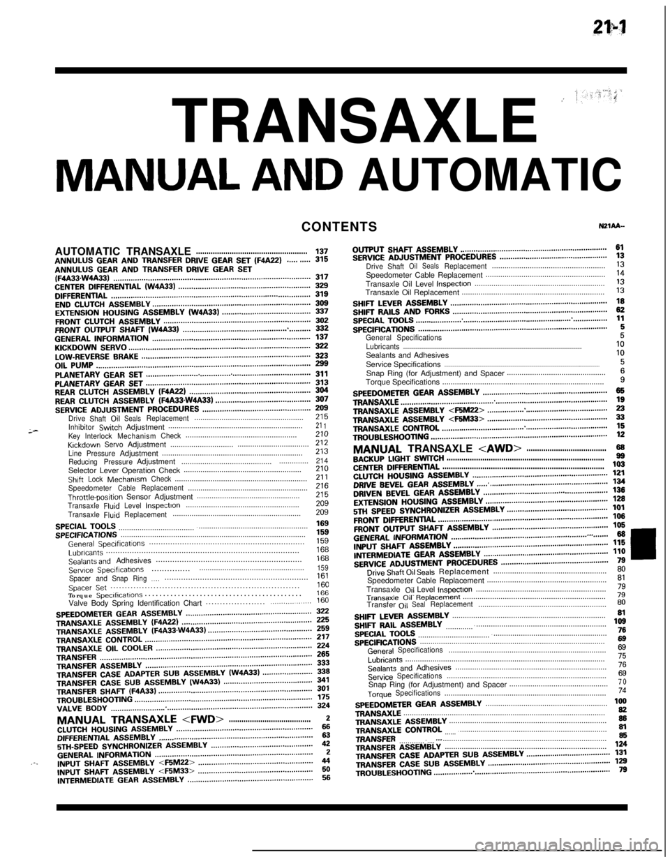
;-AUTOMATICTRANSAXLE
.....................................................137ANNULUS GEAR AND TRANSFER DRIVE GEAR SET (F4A22)..........315ANNULUS GEAR AND TRANSFER DRIVE GEAR SET(F4A33.W4A33)...........................................................................................317CENTERDIFFERENTIAL(W4A33).............................................................329DIFFERENTIAL............................................................................................319ENDCLUTCHASSEMBLY.........................................................................309EXTENSIONHOUSINGASSEMBLY(W4A33).........................................337FRONTCLUTCHASSEMBLY....................................................................302FRONTOUTPUTSHAFT(W4A33)...........................................................332GENERALINFORMATION.........................................................................137KICKDOWNSERVO....................................................................................322LOW-REVERSEBRAKE..............................................................................323OILPUMP...................................................................................................299PLANETARYGEARSET............................................................................311PLANETARYGEARSET............................................................................313REARCLUTCHASSEMBLY(F4A22)........................................................304REARCLUTCHASSEMBLY(FQA33sW4A33)............................................307SERVICEADJUSTMENTPROCEDURES..................................................Drive
Shaft,OilSealsReplacement....................................................;;;
InhibitorSwtchAdjustment................................................................21 1KeyInterlockMechanismCheck.....................................................KrckdownServoAdjustment..................................zii..............................
LinePressureAdjustment...................................................................213
ReducingPressureAdjustment.........................................................214Selector Lever Operation Check........................................................210ShiftLockMechanismCheck...............................................................21 1SpeedometerCableReplacement.........................................................Throttle-posltipn Sensor Adjustment.................................................z2:
TransaxleFluIdLevelInspectIon......................................................209
TransaxleFluidReplacement.............................................................209
SPECIALTOOLS.........................................................................................SPECIFICATIONS........................................................................................;“5”9
GeneralSpeclficatlons..................................................................1%Lubricants..................................................................................Sealants and Adhesives..............................................................izi
Serwce Speclflcatlons..................................................159...............Spacer andSnapRing.,.,.............................................................Spacer Set..................................................................1::Torque Speclflcatlons...........................................166Valve Body Spring Identification Chart.....................
.................160
SPEEDOMETERGEARASSEMBLY..........................................................TRANSAXLEASSEMBLY(WA22)............................................................zTRANSAXLE
ASSEMBLY(F4A33.W4A33)................................................TRANSAXLECONTROL.............................................................................;;;TRANSAXLE
OILCOOLER........................................................................TRANSFER..................................................................................................fg
TRANSFERASSEMBLY.............................................................................333TRANSFERCASEADAPTERSUBASSEMBLY(W4A33).......................339TRANSFER CASE SUB ASSEMBLY (W4A33)341TRANSFER SHAFT (F4A33)TROUBLESHOOTING..................................................................................................................................................................................................f;;VALVE
BODY.............................................................................................324
MANUAL TRANSAXLE
5TH-SPEEDSYNCHRONIZERASSEMBLY...............................................42GENERALINFORMATION.........................................................................2.-.INPUTfj,-,A,TASSEMBLY
INTERMEDIATE GEAR ASSEMBLY..........................................................56OUTPUT
SHAFT ASSEMBLY....................................................................61SERVICEADJUSTMENTPROCEDURES..................................................DriveShaftOilSealsReplacement......................................................;;Speedometer Cable Replacement.........................................................
Transaxle Oil Level
InspectIon..............................................................‘liTransaxle Oil Replacement....................................................................
I3
SHIFTLEVERASSEMBLY.........................................................................SHIFTRAILSANDFORKS........................................................................g
SPECIALTOOLS.........................................................................................SPECIFICATIONS........................................................................................1:
General Specifications5Lubricants..........................................................................................................................................................................10Sealants and Adhesives
Service Specifications
....................................................................................................................................................1:Snap Ring (for Adjustment) and Spacer...............................................
Torque Specifications.............................................................................
i
SPEEDOMETERGEARASSEMBLY..........................................................TRANS&G.E................................................................................................zTRANSAXLEA!jSEMBLY
TROUBLESHOOTING..................................................................................12
MANUAL TRANSAXLE
CENTERDIFFERENTIAL.............................................................................103CLUTCHHOUSINGASSEMBLY...............................................................DRIVE BEVEL GEAR ASSEMBLY;g
...... .......................................................DRIVENBEVELGEARASSEMBLY...................................a......................EXTENSIONHOUSINGASSEMBLY.........................................................;g
5Tf.jSPEEDSYNCHRONIZERASSEMBLY...............................................101
FRONTDlFFERENTlAL...............................................................................106
FRONTOUTPUTSHAFTASSEMBLY......................................................106
GENERALI~~~~MATN)N...............................................................,.,.......66INPUTSHAFTASSEMBLY........................................................................l~ER,“,EDlATEGEARASSMBLY..........................................................;;i
SERVICEADJUSTMENTPROCEDURES..................................................Drive Shaft Oil Seals Replacement......................................................;;Speedometer Cable Replacement.........................................................
Transaxle
Ojl Level lnspectlon..............................................................;l
Transaxle 011 R~pb33ment....................................................................79Transfer
OilSealReplacement.............................................................80
SHIFTLEVERASSEMBLY.........................................................................SHIFTRAILASSEMBLY............................................................................,z
SPECIALTOOLS.........................................................................................76
SPECIFICATIONS........................................................................................6g
GeneralSpecifications...........................................................................6g
Lubricants...............................................................................................75
SealantsandAdhesives........................................................................76
ServiceSpecifications............................................................................6gSnap Ring (for Adjustment) and Spacer...............................................7 o
TorqueSpecifications.............................................................................74
SPEEDOMETERGEARASSEMBLY..........................................................TRANSAXLE................................................................................................1:TRANSAXLEASSEMBLY...........................................................................86TRANSAXLE
CONTROL
.............................................................................TRANSFER...............................................................................................
g.._TRANSFERA!333lBLY.............................................................................,24
TRANSFERCASEADAPTERSUBASSEMBLY.......................................131TRANSFERCASESUBASSEMBLY.........................................................TR,,UBLES,,OO,,NG..................................................................................1;;
Page 703 of 1216
MANUAL TRANSAXLE
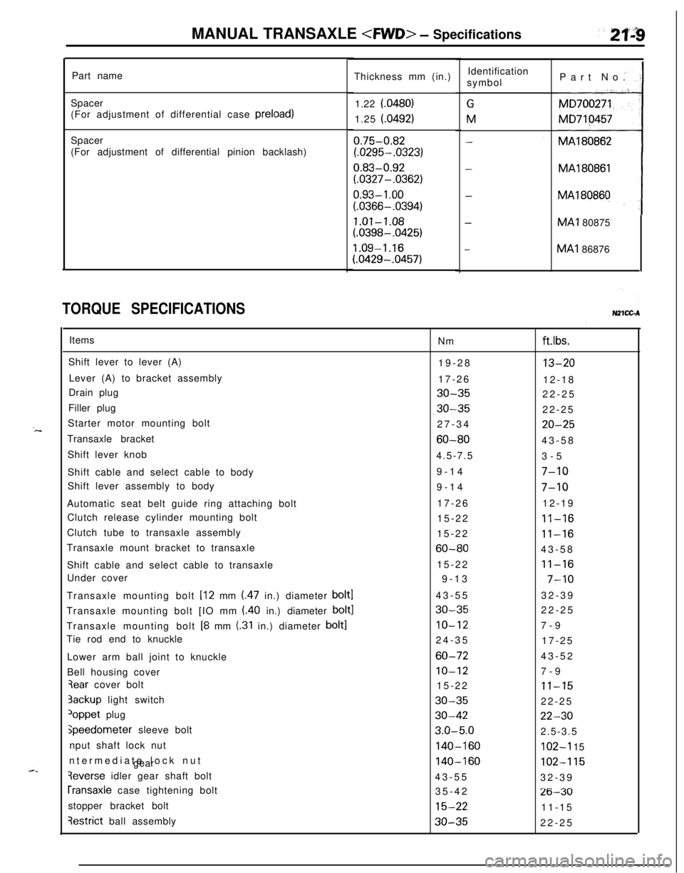
Part name
Spacer
(For adjustment of differential case preload)
Spacer
(For adjustment of differential pinion backlash)
TORQUE SPECIFICATIONSThickness mm (in.)
1.22 f.0480)
1.25 (.0492)
0.75-0.82
(.0295-.0323)
0.83-0.92
(.0327-.0362)
0.93- 1 .oo
(.0366-.0394)
1.01-1.08
(.0398-.0425)
1.09-1.16
(.0429-.0457)Identification
symbol
GM
-
-
-
-Part No.
MA180862MA1
80866MA1 80875MA1 86876
Items
Nm
Shift lever to lever (A)
19-28
Lever (A) to bracket assembly
17-26
Drain plug
30-35Filler plug
30-35Starter motor mounting bolt
27-34
Transaxle bracket
60-80Shift lever knob
4.5-7.5
Shift cable and select cable to body9-14
Shift lever assembly to body
9-14
Automatic seat belt guide ring attaching bolt17-26
Clutch release cylinder mounting bolt
15-22
Clutch tube to transaxle assembly
15-22
Transaxle mount bracket to transaxle
60-80Shift cable and select cable to transaxle15-22
Under cover
9-13
Transaxle mounting bolt [12 mm (.47 in.) diameter
bolt143-55
Transaxle mounting bolt [IO mm (.40 in.) diameter
bolt130-35Transaxle mounting bolt
[8 mm (.31 in.) diameter bolt]IO-12Tie rod end to knuckle
24-35
Lower arm ball joint to knuckle
60-72Bell housing cover
IO-123ear cover bolt
15-223ackup light switch
30-35
loppet plug30-42
jpeedometer sleeve bolt3.0-5.0nput shaft lock nut
140-160ntermediate lock nut
gear
140-160
3everse idler gear shaft bolt
43-55
rransaxle case tightening bolt
35-42
stopper bracket bolt
15-22
qestrict ball assembly30-35
ft.lbs.
13-2012-18
22-25
22-25
20-2543-58
3-5
7-10
7-1012-19
11-16
11-1643-58
11-16
7-1032-39
22-25
7-9
17-25
43-52
7-9
11-1522-25
22-302.5-3.5
102-I 15
102-11532-39
26-3011-15
22-25
Page 713 of 1216
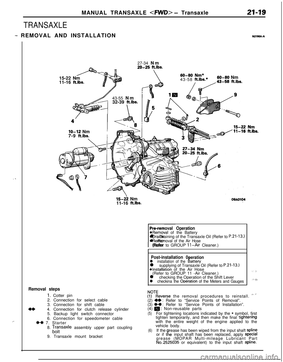
MANUAL TRANSAXLE
TRANSAXLE
- REMOVAL AND INSTALLATIONNZlMA-A
. .
,-27-34 Nm
20-25 ft.lbs.15-22 Nm
11-16
ft.lbs.43-55 Nm
32-39
ft.lbs.
\
60-80 Nm*43-58 ft.lbs.*60-80 Nm
/da-,, ft.lbs.
lo-12 NmI7-9
ft.lbs.I
15-2: Nm
11-16 ft.lbs.OOAOl~4
Pre-removal Operation@Removal of the Battery
rl Draining of the Transaxle Oil (Refer to
P.21-13.)l Removal of the Air Hose(Refer to GROUP 11-Air Cleaner.)
Post-installation 0erationl installation of theI!attery
l supplying of Transaxle Oil (Refer to P.21-13.)*Installation of the Air Hose
(Refer to GROUP 11 -Air Cleaner.)
l checking the Operation of the Shift Lever
l checkina the Ooeration of the Meters and Gauges
Removal steps
1. Cotter pin
2. Connection for select cable
3. Connection for shift cable
4*4. Connection for clutch release cylinder
5. Backup light switch connector
6. Connection for speedometer cable
I)* 7. Starter
8.
Lfrsaxle assembly upper part coupling
9. Transaxle mount bracket
ZKeverse the removal procedures to reinstall. ” ’(2) W : Refer to “Service Points of Removal”.
(3) ~~ : Refer to “Service Points of Installation”.
(4) m : Non-reusable parts
(5)For tightening locations indicated by the * symbol, fjrst
tighten temporarily, and then make the final tightenrngwith the entire weight of the engine applied to the
vehicle body.
(6)If therease has been wiped from the input shaft spline
or if taeinput shaft has been replaced, apply specralgrease (MOPAR Multi-mileage Lubricant Part
No.2525035 or equivalent) to the input shaft Spline.
Page 717 of 1216
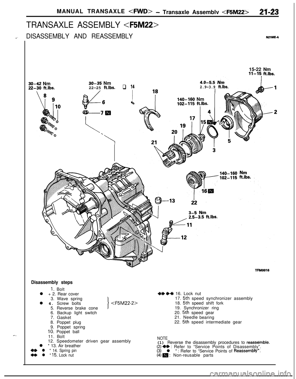
MANUAL TRANSAXLE
TRANSAXLE ASSEMBLY
.._DISASSEMBLY AND REASSEMBLYN21ME-A
__
30-42 Nm22-30 ft.lbs.30-35 Nm22-25 ftlbs.q l4
ig5 !
----7m
IQ15-22 Nm
II-15 ft.lbs.
4.0-5.5 Nm2.9-3.9 ft.lbs.1I”I
a
140-160 Nmf
102-115 ft.lbs.
Disassembly steps
1. Bolt
l + 2. Rear cover
3. Wave spring
l 4. Screw bolts
5. Reverse brake cone
6. Backup light switch
7. Gasket
9. Poppet spring
10. Poppet ball
11. Bolt
12. Speedometer driven gear assembly
l * 13. Air breather
*I) l * 14. Spring pin+I) l * 15. Lock nut
140-160102-115
TFMOOl6
+e I)+ 16. Lock nut
17. 5th speed synchronizer assembly
18. 5th speed shift fork
19. Synchronizer ring
20. 5th speed gear
21.Needle
bearing
22. 5th speed intermediate gear
NOTE(1) Reverse the disassembly procedures to reasseinble.
(2) ++ : Refer to “Service Points of Disassembly”.(3) l * : Refer to “Service Points of ReaSsembly”:(4) m : Non-reusable parts