auto stop MITSUBISHI ECLIPSE CROSS 2018 Owner's Manual (in English)
[x] Cancel search | Manufacturer: MITSUBISHI, Model Year: 2018, Model line: ECLIPSE CROSS, Model: MITSUBISHI ECLIPSE CROSS 2018Pages: 417, PDF Size: 74.06 MB
Page 23 of 417
Filling the fuel tank 3-4 General information
3
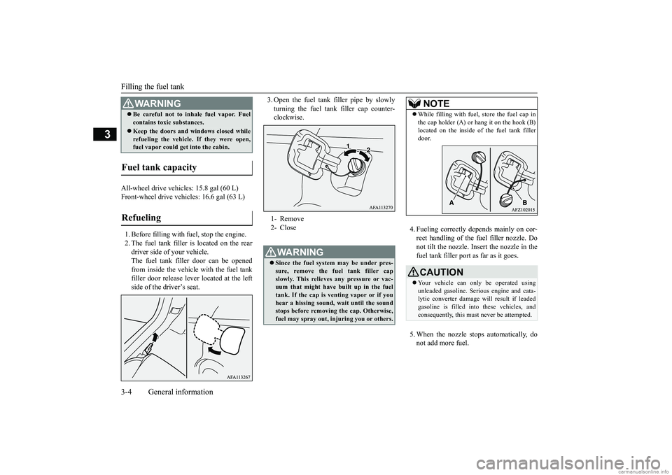
All-wheel drive vehicles: 15.8 gal (60 L) Front-wheel drive vehicles: 16.6 gal (63 L) 1. Before filling with fuel, stop the engine. 2. The fuel tank filler is located on the rear driver side of your vehicle. The fuel tank filler door can be openedfrom inside the vehicle with the fuel tank filler door release le
ver located at the left
side of the driver’s seat.
3. Open the fuel tank filler pipe by slowly turning the fuel tank filler cap counter- clockwise.
4. Fueling correctly depends mainly on cor- rect handling of the fuel filler nozzle. Do not tilt the nozzle. Insert the nozzle in thefuel tank filler port as far as it goes. 5. When the nozzle stops automatically, do not add more fuel.
Be careful not to inhale fuel vapor. Fuel contains toxic substances. Keep the doors and windows closed while refueling the vehicle. If they were open,fuel vapor could get into the cabin.
Fuel tank capacity Refueling
WA R N I N G
1- Remove 2- CloseWA R N I N G Since the fuel system may be under pres- sure, remove the fuel tank filler cap slowly. This relieves any pressure or vac- uum that might have built up in the fueltank. If the cap is venting vapor or if you hear a hissing sound, wait until the sound stops before removing the cap. Otherwise,fuel may spray out, injuring you or others.
NOTE
While filling with fuel, store the fuel cap in the cap holder (A) or hang it on the hook (B) located on the inside of the fuel tank filler door.CAUTION Your vehicle can only be operated using unleaded gasoline. Serious engine and cata- lytic converter damage will result if leadedgasoline is filled into these vehicles, and consequently, this must never be attempted.
BK0252700US.bo
ok 4 ページ 2017年10月4日 水曜日 午後4時54分
Page 26 of 417
Telematics Control Unit (TCU) (if so equipped)
General information 3-7
3
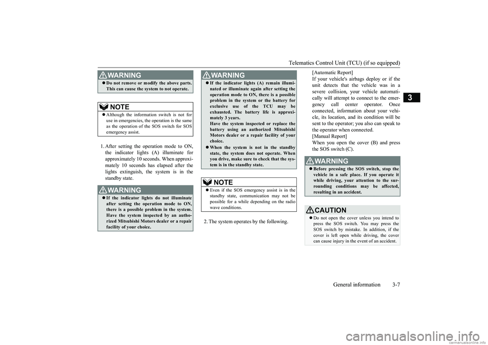
1. After setting the operation mode to ON, the indicator lights (A) illuminate for approximately 10 seconds. When approxi-mately 10 seconds has elapsed after the lights extinguish, the system is in the standby state.
2. The system operates by the following.
[Automatic Report] If your vehicle's airbags deploy or if the unit detects that the vehicle was in a severe collision, your vehicle automati-cally will attempt to connect to the emer- gency call center operator. Once connected, information about your vehi-cle, its location, and its condition will be sent to the operator; you also can speak to the operator when connected.[Manual Report]When you open the cover (B) and press the SOS switch (C).
WA R N I N G Do not remove or modify the above parts. This can cause the system to not operate.NOTE
Although the information switch is not for use in emergencies, the operation is the same as the operation of the SOS switch for SOSemergency assist.WA R N I N G If the indicator lights do not illuminate after setting the operation mode to ON,there is a possible problem in the system. Have the system inspected by an autho- rized Mitsubishi Motors dealer or a repair facility of your choice.
If the indicator lights (A) remain illumi- nated or illuminate again after setting the operation mode to ON, there is a possible problem in the system or the battery for exclusive use of the TCU may beexhausted. The battery life is approxi- mately 3 years. Have the system inspected or replace thebattery using an authorized Mitsubishi Motors dealer or a repair facility of your choice. When the system is not in the standby state, the system does not operate. Whenyou drive, make sure to check that the sys- tem is in the standby state.NOTE
Even if the SOS emergency assist is in the standby state, communication may not bepossible for a while depending on the radio wave conditions.WA R N I N G
WA R N I N G Before pressing the SOS switch, stop the vehicle in a safe place. If you operate it while driving, your attention to the sur- rounding conditions may be affected,resulting in an accident.CAUTION Do not open the cover unless you intend to press the SOS switch. You may press the SOS switch by mistake. In addition, if the cover is left open while driving, the covercan cause injury in the event of an accident.
BK0252700US.bo
ok 7 ページ 2017年10月4日 水曜日 午後4時54分
Page 30 of 417
Telematics Control Unit (TCU) (if so equipped)
General information 3-11
3
Geo-fence If the specified area is set beforehand using the smartphone app, an alert is sent to the smartphone using a short messageservice (SMS), e-mail, or push notifica- tion when the vehicle enters or leaves that area. Curfew If the specified time of day is set before- hand using the smartphone app, an alert issent to the smartphone using a short mes-sage service (SMS), e-mail, or push noti- fication when the curfew is violated. Vehicle settings You can change settings of items such as “Auto Fold Mirrors” and “Headlight Timeout when Exiting Vehicle” from thesmartphone app.
Model name: LE920A4-NA Auto FCC ID: RI7LE920A4NAYour TCU operates on a radio frequency sub-ject to Federal Communications Commission (FCC) Rules (for vehicles sold in U.S.A.). This device complies with Part 15 of the FCCRules. Operation is subject to the following two conditions: This device may not cause harmful inter- ference. This device must accept any interference received, including interference that may cause undesired operation.
FCC Notice: This equipment has been tested and found to comply with the limits for a Class B digital device, pursuant to part 15 of
WA R N I N G Do not use the TCU if children, persons in need of care, pets, etc., are in the vehicle. Even if the remote climate control is used, the cabin may become too hot or cold if the system stops automatically or due tosome other reason. The cabin temperature may quickly rise in sunshine, which poses a risk of heat stroke and dehydration. Incold weather, on the other hand, the cabin temperature may quickly drop. Either of which could lead to death in the worstcase. In addition, children can activate switches and controls, resulting in an injury orfatal accident.CAUTION When using the remote climate control, do not use a car cover.NOTE
Air conditioning performance may deterio- rate under the following conditions: • In extremely hot weather • In hot sunshine • In extremely cold weather The remote climate control turns off auto- matically after approximately 10 minutes.The remote climate control can be operated up to two times consecutively.
Use the remote climate control according to the state or local regulations regarding idling vehicles.
General information
CAUTION Changes or modifications made to this equipment not expressly approved by themanufacturer may void the FCC authoriza- tion to operate this equipment.NOTE
BK0252700US.bo
ok 11 ページ 2017年10月4日 水曜日 午後4時54分
Page 42 of 417
Head restraints
Seat and restraint systems 4-9
4
Each time the switch is pressed, the mode changes to the next one in the following sequence: OFF
HI
LO
OFF.
N00404301640
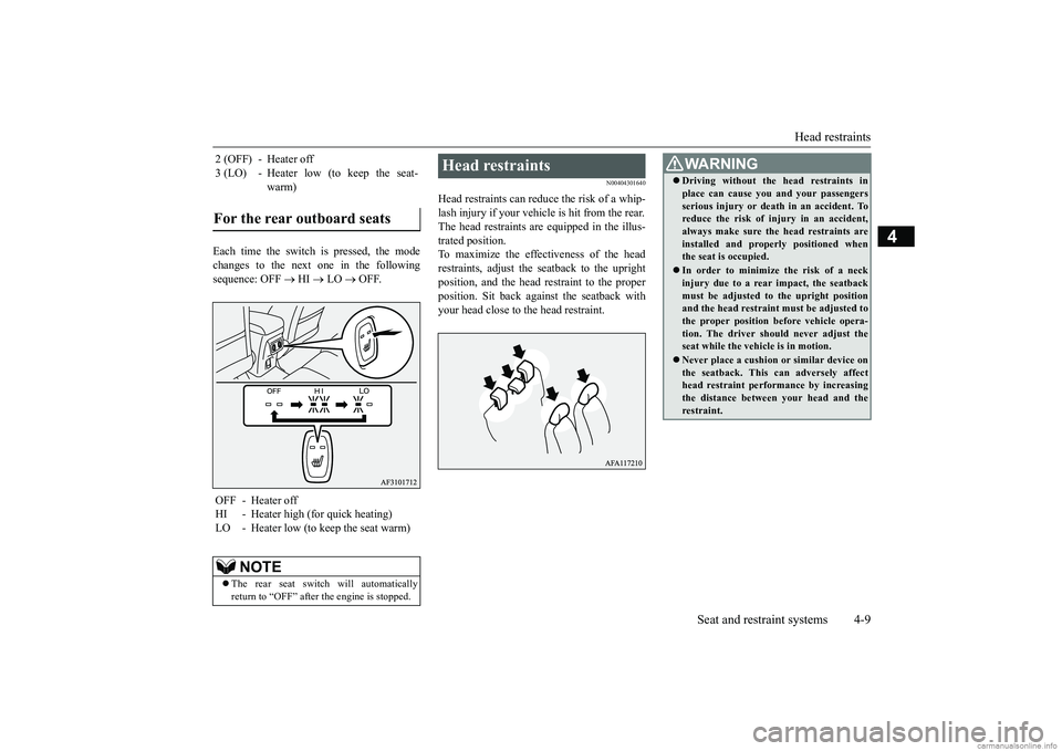
Head restraints can reduce the risk of a whip- lash injury if your vehicle is hit from the rear.The head restraints are equipped in the illus- trated position. To maximize the effectiveness of the headrestraints, adjust the seatback to the upright position, and the head
restraint to the proper
position. Sit back against the seatback withyour head close to the head restraint.
2 (OFF) - Heater off 3 (LO) - Heater low (to keep the seat-
warm)
For the rear outboard seats
OFF - Heater offHI - Heater high (for quick heating) LO - Heater low (to keep the seat warm)
NOTE
The rear seat switch will automatically return to “OFF” after the engine is stopped.
Head restraints
WA R N I N G Driving without the head restraints in place can cause you and your passengers serious injury or death in an accident. To reduce the risk of injury in an accident, always make sure the head restraints areinstalled and properly positioned when the seat is occupied. In order to minimize the risk of a neck injury due to a rear impact, the seatback must be adjusted to the upright positionand the head restraint must be adjusted to the proper position before vehicle opera- tion. The driver should never adjust theseat while the vehicle is in motion. Never place a cushion or similar device on the seatback. This can adversely affect head restraint performance by increasing the distance between your head and therestraint.
BK0252700US.bo
ok 9 ページ 2017年10月4日 水曜日 午後4時54分
Page 47 of 417
Seat belts 4-14 Seat and restraint systems
4
N00406201542
All seats are equipped with a seat belt which uses one combined lap-and-shoulder belt with an emergency locking retractor. This system is designed to provide both com- fort and safety. It permits full extension and automatic retraction of the belts during nor- mal vehicle operation. A sensing device
inside the belt retractor is designed to lock the retractor in the event of a sudden change in the vehicle’s motion.
To reduce the risk to the driver of serious injury or death during deployment of the driver’s airbag, always properly wear the seat belt and adjust the driver’s seat as far back as possible while maintaining a posi-tion that still enables you to fully apply the pedals, easily control the steering wheel, and safely operate the vehicle. To reduce the risk to a front seat passen- ger of serious injury or death from adeploying airbag, make sure the passenger always wears the seat belt properly, remains seated all the way back andupright in their seat, and moves the seat as far back as possible. Refer to “Supplemen- tal Restraint System (SRS) - airbag” onpage 4-30 for additional information. Never hold an infant or child in your arms or on your lap when riding in this vehicle even when you are wearing your seat belt. Never place any part of the seat belt youare wearing around an infant or child. Failure to follow these simple instructions creates a risk of serious injury or death toyour child in the event of an accident or sudden stop.WA R N I N G
Children 12 years old and under should always ride in the rear seat and be prop- erly restrained. This reduces their risk of serious injury or death in an accident, especially due to a deploying front passen-ger’s airbag. Refer to “Child restraint sys- tems” on page 4-22 for additional information. Any child who is too small to properly wear a seat belt must be properlyrestrained in an appropriate child restraint system. Infants MUST be placed in a rear-facing child safety seat and positioned in the rear seat. In the event of an accident, all seat belt assemblies, including retractors andattachment hardware, should be inspected by an authorized Mitsubishi Motors dealer to determine whether replacementis necessary.
Seat belt instructions
WA R N I N G
NOTE
For instructions on installing a child restraint system using a seat belt, refer to “Installing a child restraint system using the seat belt” on page 4-27.
BK0252700US.bo
ok 14 ページ 2017年10月4日 水曜日 午後4時54分
Page 113 of 417
Power door locks 5-34 Features and controls
5
The warning display will be displayed on the information screen in the multi-information display.
N00517301078
If the ignition switch is turned to the “ON”position or the operation mode is in any mode other than OFF, when you push the lock knobforward with the driver’s door or passenger’sdoor open, the lock knob will automatically return to the unlocked position.
N00503801173
If the driver’s door is opened while the engine is stopped and the operation mode is in any mode other than OFF, the operation mode ON buzzer will sound intermittently to remindyou put the operation mode in OFF. The warning display will be displayed on the information screen in the multi-informationdisplay.
N00509301659
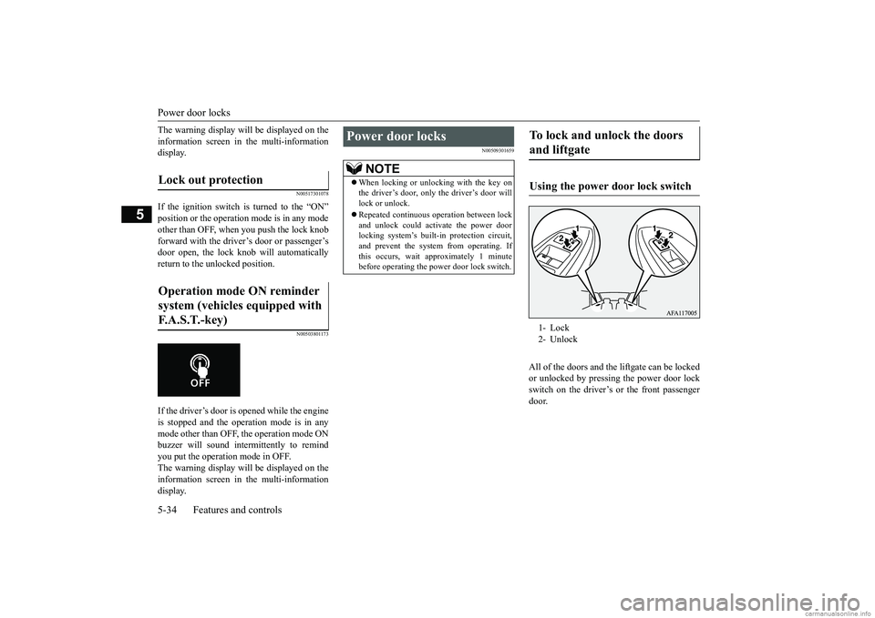
All of the doors and the
liftgate can be locked
or unlocked by pressing the power door lock switch on the driver’s or the front passengerdoor.
Lock out protection Operation mode ON reminder system (vehicles equipped with F. A . S . T. - k e y )
Power door locks
NOTE
When locking or unlocking with the key on the driver’s door, only the driver’s door will lock or unlock. Repeated continuous operation between lock and unlock could activate the power door locking system’s built
-in protection circuit,
and prevent the system from operating. If this occurs, wait approximately 1 minute before operating the power door lock switch.
To lock and unlock the doors and liftgate Using the power door lock switch 1- Lock 2- Unlock
BK0252700US.bo
ok 34 ページ 2017年10月4日 水曜日 午後4時54分
Page 118 of 417
Theft-alarm system
Features and controls 5-39
5
N00510401243
The alarm will be activated if any of the fol- lowing occur while the vehicle is parked and the system is armed.
One of the doors and the liftgate is opened without using the keyless entry system or the F.A.S.T.-key operation. The engine hood is opened.
N00582500053
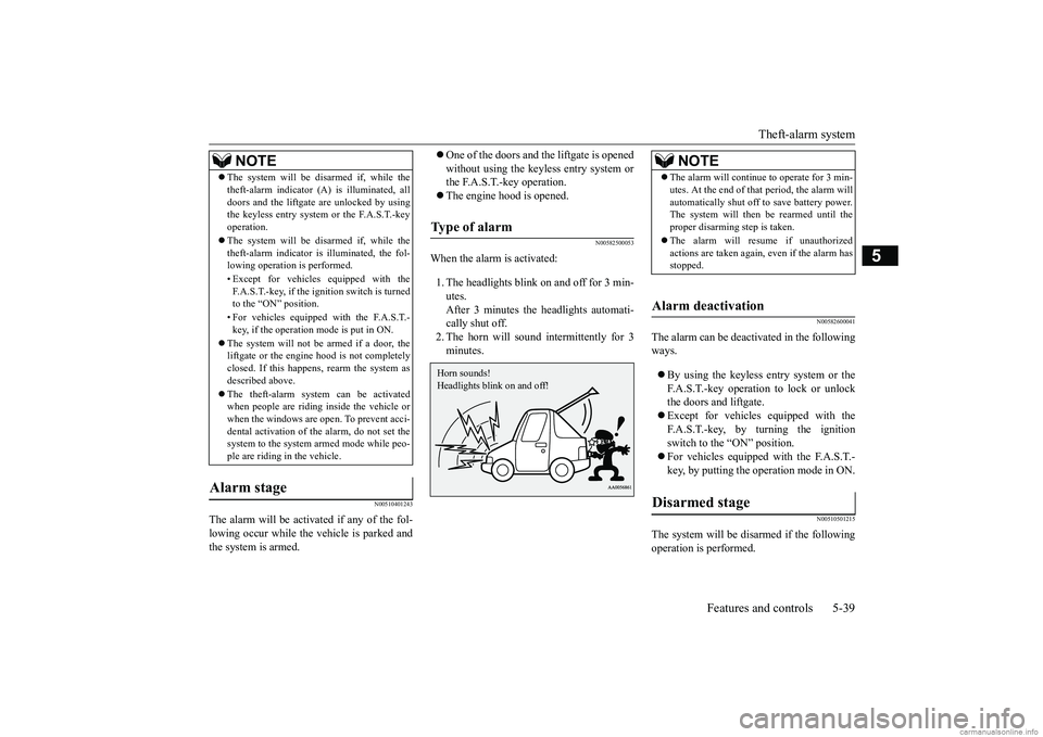
When the alarm is activated: 1. The headlights blink on and off for 3 min- utes.After 3 minutes the headlights automati-cally shut off. 2. The horn will sound intermittently for 3 minutes.
N00582600041
The alarm can be deactivated in the followingways. By using the keyless entry system or the F.A.S.T.-key operation to lock or unlock the doors and liftgate. Except for vehicles equipped with the F.A.S.T.-key, by turning the ignition switch to the “ON” position. For vehicles equipped with the F.A.S.T.- key, by putting the operation mode in ON.
N00510501215
The system will be disarmed if the followingoperation is performed.
The system will be disarmed if, while the theft-alarm indicator (A) is illuminated, all doors and the liftgate are unlocked by using the keyless entry system or the F.A.S.T.-key operation. The system will be disarmed if, while the theft-alarm indicator is illuminated, the fol-lowing operation is performed. • Except for vehicles equipped with the F.A.S.T.-key, if the ignition switch is turned to the “ON” position. • For vehicles equipped with the F.A.S.T.- key, if the operation mode is put in ON.
The system will not be armed if a door, the liftgate or the engine hood is not completely closed. If this happens, rearm the system asdescribed above. The theft-alarm system can be activated when people are riding inside the vehicle or when the windows are open. To prevent acci- dental activation of th
e alarm, do not set the
system to the system armed mode while peo- ple are riding in the vehicle.
Alarm stage
NOTE
Type of alarm Horn sounds! Headlights blink on and off!
NOTE
The alarm will continue to operate for 3 min- utes. At the end of that period, the alarm will automatically shut off to save battery power. The system will then
be rearmed until the
proper disarming step is taken. The alarm will resume if unauthorized actions are taken again, even if the alarm hasstopped.
Alarm deactivation Disarmed stage
BK0252700US.bo
ok 39 ページ 2017年10月4日 水曜日 午後4時54分
Page 119 of 417
Power window control 5-40 Features and controls
5
Except for vehicles equipped with the F.A.S.T.-key, if the ignition switch is turned to the “ON” position. For vehicles equipped with the F.A.S.T.- key, if the operation mode is put in ON. All doors and the liftgate are unlocked by using the keyless entry system or theF.A.S.T.-key operation.
N00510601160
Use the following procedure to test the sys- tem: 1. Lower the driver’s window. 2. Arm the system as explained in “Armedstage”. 3. Make sure that the theft-alarm indicator comes on and flashes for approximately20 seconds. 4. Wait a few seconds and then unlock the driver’s side door by using the inside doorlock knob. Open the door. 5. Make sure that the horn sounds intermit- tently and the headlights blink when adoor is opened.
6. Disarm the system by unlocking all doors and the liftgate by using the keyless entry system or the F.A.S.T.-key operation.
N00510801436
NOTE
If the UNLOCK button on the key, or the driver’s or front passenger’s doorlock/unlock switch is pressed when all doors and the liftgate are closed and no door is opened within approximately 30 seconds, re-arming will automatically occur.Disarm...by using the keyless entry system or F.A.S.T.-key operation
The amount of time after unlocking until the vehicle relocks automatically can be adjusted. See an au
thorized Mitsubishi
Motors dealer for details. On vehicles equipped with the SmartphoneLink Display Audio, the functions can be adjusted on the screen. For details, refer to a separate owner’s manual. Once the system has been disarmed, it can- not be rearmed except by repeating the arm-ing procedure.
Testing the theft-alarm system
NOTE
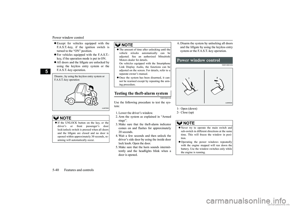
Power window control 1- Open (down) 2- Close (up)
NOTE
Never try to operate the main switch and sub-switch in different directions at the same time. This will freeze the window in posi- tion. Operating the power windows repeatedly with the engine stopped will run down thebattery. Use the window switches only while the engine is running.
BK0252700US.bo
ok 40 ページ 2017年10月4日 水曜日 午後4時54分
Page 120 of 417
Power window control
Features and controls 5-41
5
N00548701153
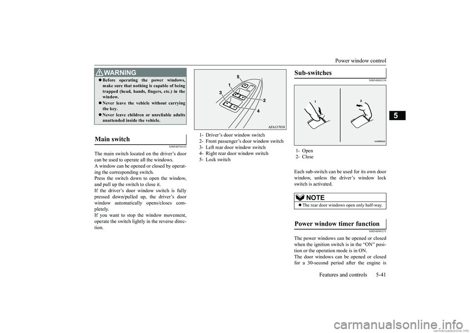
The main switch located on the driver’s door can be used to operate all the windows. A window can be opened or closed by operat-ing the corresponding switch. Press the switch down to open the window, and pull up the switch to close it.If the driver’s door window switch is fully pressed down/pulled up, the driver’s door window automatically opens/closes com-pletely. If you want to stop the window movement, operate the switch lightly in the reverse direc-tion.
N00548801138
Each sub-switch can be
used for its own door
window, unless the driver’s window lock switch is activated.
N00548901171
The power windows can be opened or closed when the ignition switch is in the “ON” posi- tion or the operation mode is in ON.The door windows can be opened or closed for a 30-second period after the engine is
WA R N I N G Before operating the power windows, make sure that nothing is capable of being trapped (head, hands, fingers, etc.) in the window. Never leave the vehicle without carrying the key. Never leave children or unreliable adults unattended inside the vehicle.
Main switch
1- Driver’s door window switch 2- Front passenger’s door window switch 3- Left rear door window switch 4- Right rear door window switch5- Lock switch
Sub-switches 1- Open 2- Close
NOTE
The rear door windows open only half-way.
Power window timer function
BK0252700US.bo
ok 41 ページ 2017年10月4日 水曜日 午後4時54分
Page 121 of 417
Power window control 5-42 Features and controls
5
stopped. However, once the driver’s door or the front passenger’s door is opened, the power windows cannot be operated.
N00549001182
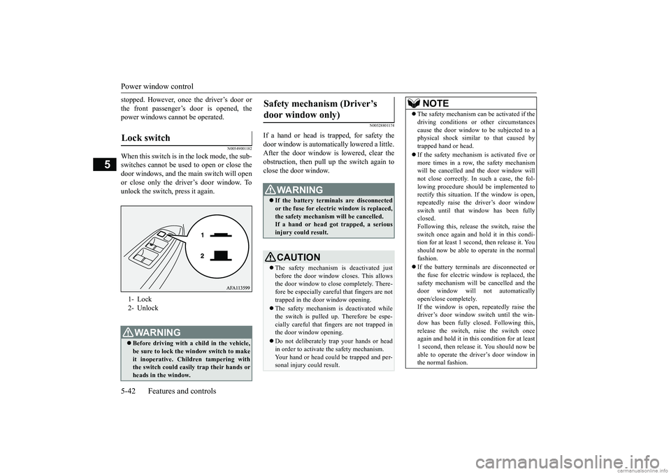
When this switch is in the lock mode, the sub-switches cannot be used to open or close the door windows, and the main switch will openor close only the driver’s door window. Tounlock the switch, press it again.
N00528801174
If a hand or head is trapped, for safety thedoor window is automatically lowered a little. After the door window is lowered, clear the obstruction, then pull up the switch again toclose the door window.
Lock switch 1- Lock 2- UnlockWA R N I N G Before driving with a child in the vehicle, be sure to lock the window switch to make it inoperative. Children tampering withthe switch could easily trap their hands or heads in the window.
Safety mechanism (Driver’s door window only)
WA R N I N G If the battery terminals are disconnected or the fuse for electric window is replaced, the safety mechanism will be cancelled.If a hand or head got trapped, a serious injury could result.CAUTION The safety mechanism is deactivated just before the door window closes. This allows the door window to close completely. There- fore be especially careful that fingers are nottrapped in the door window opening. The safety mechanism is deactivated while the switch is pulled up. Therefore be espe- cially careful that fingers are not trapped inthe door window opening. Do not deliberately trap your hands or head in order to activate the safety mechanism. Your hand or head could be trapped and per- sonal injury could result.
NOTE
The safety mechanism can be activated if the driving conditions or other circumstances cause the door window to be subjected to a physical shock similar to that caused by trapped hand or head. If the safety mechanism is activated five or more times in a row, the safety mechanismwill be cancelled and the door window will not close correctly. In such a case, the fol- lowing procedure should be implemented torectify this situation. If the window is open, repeatedly raise the driver’s door window switch until that window has been fullyclosed. Following this, release the switch, raise the switch once again and hol
d it in this condi-
tion for at least 1 second, then release it. You should now be able to operate in the normal fashion. If the battery terminals are disconnected or the fuse for electric window is replaced, thesafety mechanism will be cancelled and the door window will not automatically open/close completely.If the window is open, repeatedly raise the driver’s door window switch until the win- dow has been fully closed. Following this, release the switch, raise the switch once again and hold it in this
condition for at least
1 second, then release it. You should now be able to operate the driver’s door window in the normal fashion.
BK0252700US.bo
ok 42 ページ 2017年10月4日 水曜日 午後4時54分