MITSUBISHI ENDEAVOR 2004 Service Repair Manual
ENDEAVOR 2004
MITSUBISHI
MITSUBISHI
https://www.carmanualsonline.info/img/19/57105/w960_57105-0.png
MITSUBISHI ENDEAVOR 2004 Service Repair Manual
Trending: module location, Anchor, headrest, schedule, tcl, recommended oil, engine coolant
Page 1451 of 3870
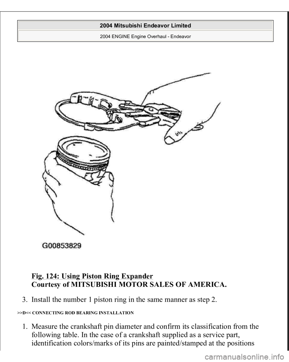
Fig. 124: Using Piston Ring Expander
Courtesy of MITSUBISHI MOTOR SALES OF AMERICA.
3. Install the number 1 piston ring in the same manner as step 2.
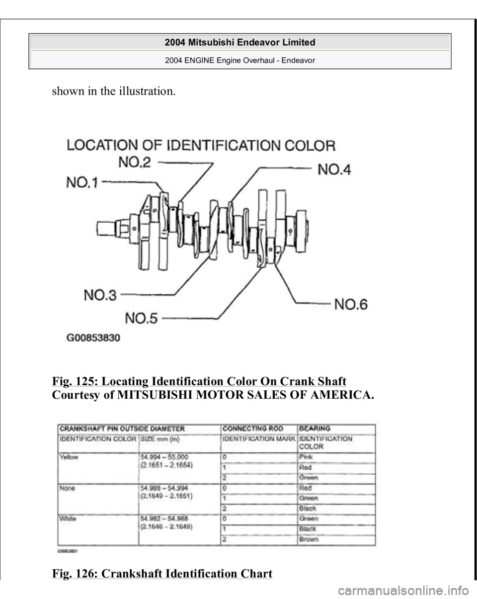
>>D<< CONNECTING ROD BEARING INSTALLATION 1. Measure the crankshaft pin diameter and confirm its classification from the
following table. In the case of a crankshaft supplied as a service part,
identification colors/marks of its
pins are
painte
d/stam
ped at the
positions
2004 Mitsubishi Endeavor Limited 2004 ENGINE Engine Overhaul - Endeavor
Page 1452 of 3870
shown in the illustration.
Fig. 125: Locating Identification Color On Crank Shaft
Courtesy of MITSUBISHI MOTOR SALES OF AMERICA.
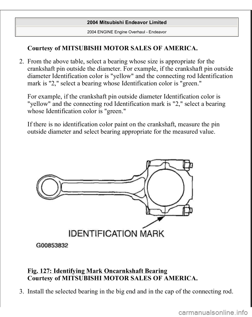
Fig. 126: Crankshaft Identification Chart
2004 Mitsubishi Endeavor Limited 2004 ENGINE Engine Overhaul - Endeavor
Page 1453 of 3870
Courtesy of MITSUBISHI MOTOR SALES OF AMERICA
.
2. From the above table, select a bearing whose size is appropriate for the
crankshaft pin outside the diameter. For example, if the crankshaft pin outside
diameter Identification color is "yellow" and the connecting rod Identification
mark is "2," select a bearing whose Identification color is "green."
For example, if the crankshaft pin outside diameter Identification color is
"yellow" and the connecting rod Identification mark is "2," select a bearing
whose Identification color is "green."
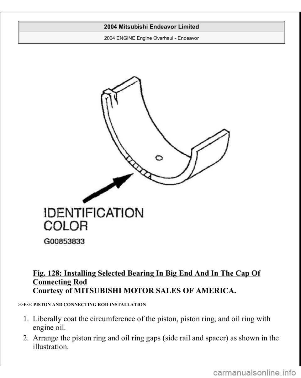
If there is no identification color paint on the crankshaft, measure the pin
outside diameter and select bearing appropriate for the measured value.
Fig. 127: Identifying Mark Oncarnkshaft Bearing
Courtesy of MITSUBISHI MOTOR SALES OF AMERICA.
3. Install the selected bearin
g in the bi
g end and in the ca
p of the connectin
g rod.
2004 Mitsubishi Endeavor Limited 2004 ENGINE Engine Overhaul - Endeavor
Page 1454 of 3870
Fig. 128: Installing Selected Bearing In Big End And In The Cap Of Connecting Rod
Courtesy of MITSUBISHI MOTOR SALES OF AMERICA.
>>E<< PISTON AND CONNECTING ROD INSTALLATION 1. Liberally coat the circumference of the piston, piston ring, and oil ring with
engine oil.
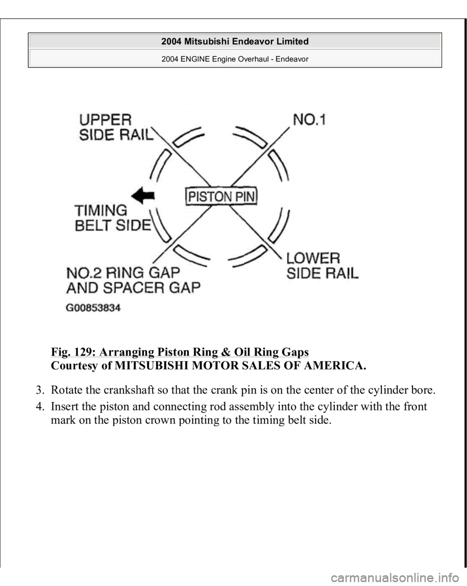
2. Arrange the piston ring and oil ring gaps (side rail and spacer) as shown in the
illustration.
2004 Mitsubishi Endeavor Limited 2004 ENGINE Engine Overhaul - Endeavor
Page 1455 of 3870
Fig. 129: Arranging Piston Ring & Oil Ring Gaps
Courtesy of MITSUBISHI MOTOR SALES OF AMERICA.
3. Rotate the crankshaft so that the crank pin is on the center of the cylinder bore.
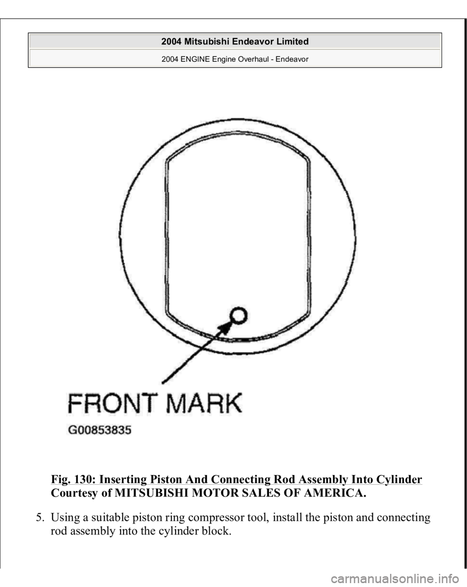
4. Insert the piston and connecting rod assembly into the cylinder with the front
mark on the
piston crown
pointin
g to the timin
g belt side.
2004 Mitsubishi Endeavor Limited 2004 ENGINE Engine Overhaul - Endeavor
Page 1456 of 3870
Fig. 130: Inserting Piston And Connecting Rod Assembly Into Cylinder
Courtesy of MITSUBISHI MOTOR SALES OF AMERICA.
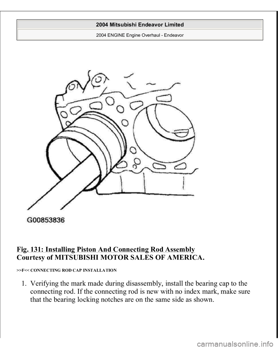
5. Using a suitable piston ring compressor tool, install the piston and connecting
rod assembly into the cylinder block.
2004 Mitsubishi Endeavor Limited 2004 ENGINE Engine Overhaul - Endeavor
Page 1457 of 3870
Fig. 131: Installing Piston And Connecting Rod Assembly
Courtesy of MITSUBISHI MOTOR SALES OF AMERICA.
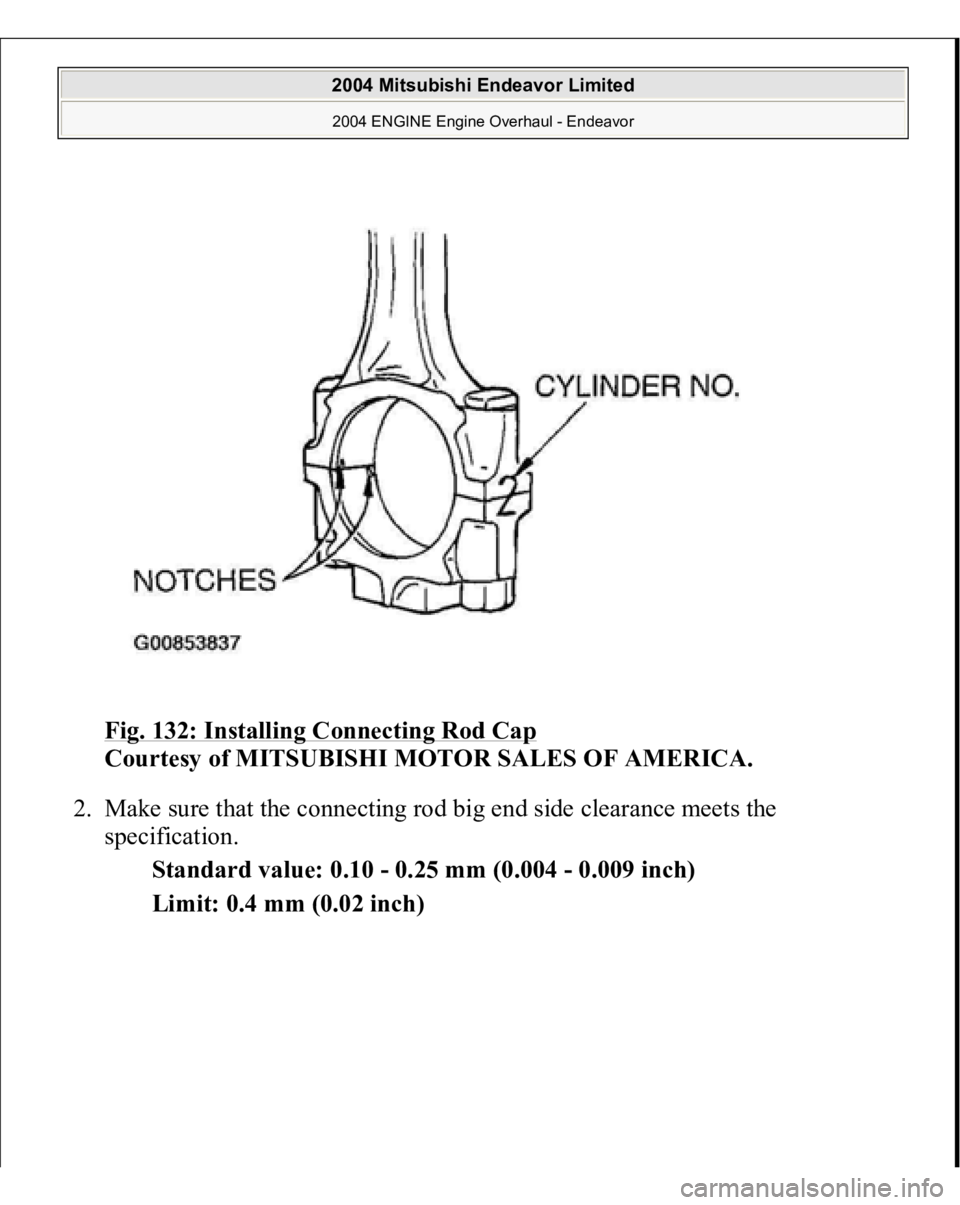
>>F<< CONNECTING ROD CAP INSTALLATION 1. Verifying the mark made during disassembly, install the bearing cap to the
connecting rod. If the connecting rod is new with no index mark, make sure
that the bearin
g lockin
g notches are on the same side as shown.
2004 Mitsubishi Endeavor Limited 2004 ENGINE Engine Overhaul - Endeavor
Page 1458 of 3870
Fig. 132: Installing Connecting Rod Cap
Courtesy of MITSUBISHI MOTOR SALES OF AMERICA.
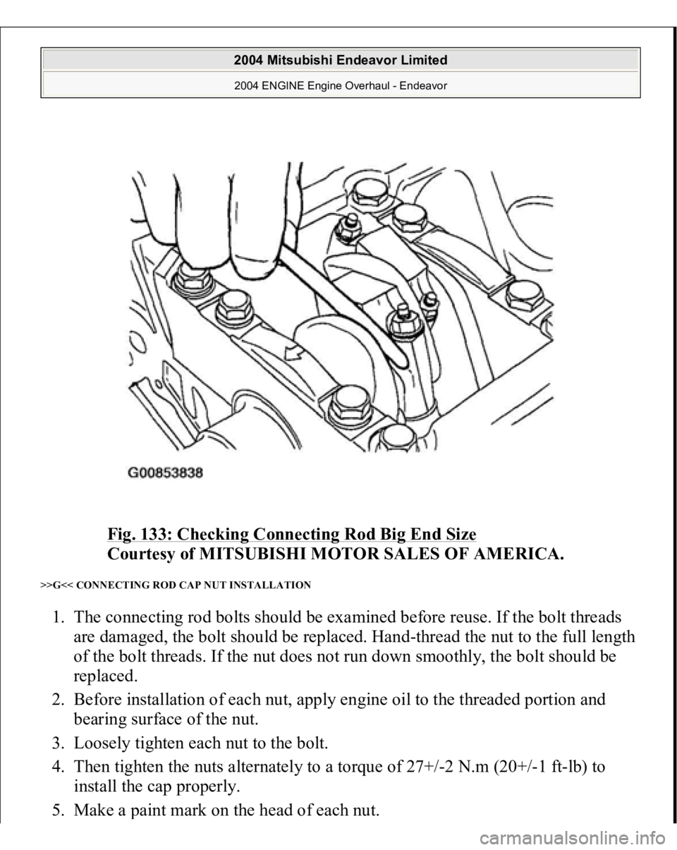
2. Make sure that the connecting rod big end side clearance meets the
specification.
Standard value: 0.10 - 0.25 mm (0.004 - 0.009 inch)
Limit: 0.4 mm (0.02 inch)
2004 Mitsubishi Endeavor Limited 2004 ENGINE Engine Overhaul - Endeavor
Page 1459 of 3870
Fig. 133: Checking Connecting Rod Big End Size
Courtesy of MITSUBISHI MOTOR SALES OF AMERICA.
>>G<< CONNECTING ROD CAP NUT INSTALLATION 1. The connecting rod bolts should be examined before reuse. If the bolt threads
are damaged, the bolt should be replaced. Hand-thread the nut to the full length
of the bolt threads. If the nut does not run down smoothly, the bolt should be
replaced.
2. Before installation of each nut, apply engine oil to the threaded portion and
bearing surface of the nut.
3. Loosely tighten each nut to the bolt.
4. Then tighten the nuts alternately to a torque of 27+/-2 N.m (20+/-1 ft-lb) to
install the cap properly.
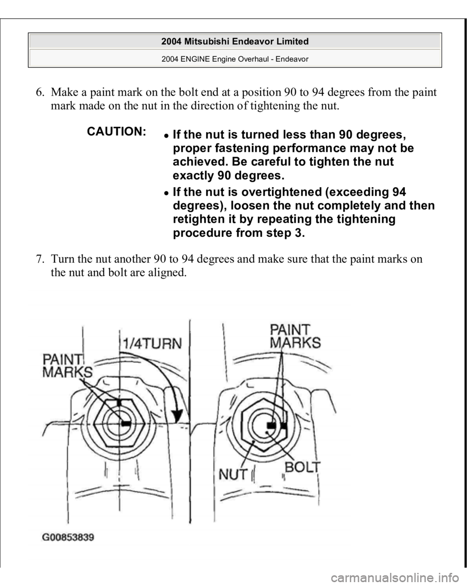
5. Make a
paint mark on the head of each nut.
2004 Mitsubishi Endeavor Limited 2004 ENGINE Engine Overhaul - Endeavor
Page 1460 of 3870
6. Make a paint mark on the bolt end at a position 90 to 94 degrees from the paint
mark made on the nut in the direction of tightening the nut.
7. Turn the nut another 90 to 94 degrees and make sure that the paint marks on
the nut and bolt are aligned.
CAUTION:
If the nut is turned less than 90 degrees,
proper fastening performance may not be
achieved. Be careful to tighten the nut
exactly 90 degrees. If the nut is overtightened (exceeding 94
degrees), loosen the nut completely and then
retighten it by repeating the tightening
procedure from step 3.
2004 Mitsubishi Endeavor Limited 2004 ENGINE Engine Overhaul - Endeavor
Trending: Egr valve, maintenance schedule, module location, transmission control, rear entertainment, windshield wipers, heating
