MITSUBISHI ENDEAVOR 2004 Service Repair Manual
ENDEAVOR 2004
MITSUBISHI
MITSUBISHI
https://www.carmanualsonline.info/img/19/57105/w960_57105-0.png
MITSUBISHI ENDEAVOR 2004 Service Repair Manual
Trending: Seat, low oil pressure, belt, maintenance, clutch, length, Anchor
Page 3541 of 3870
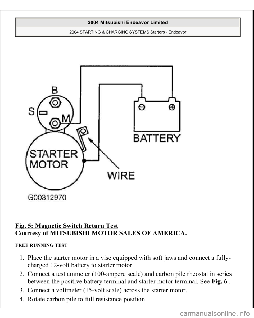
Fig. 5: Magnetic Switch Return Test
Courtesy of MITSUBISHI MOTOR SALES OF AMERICA.
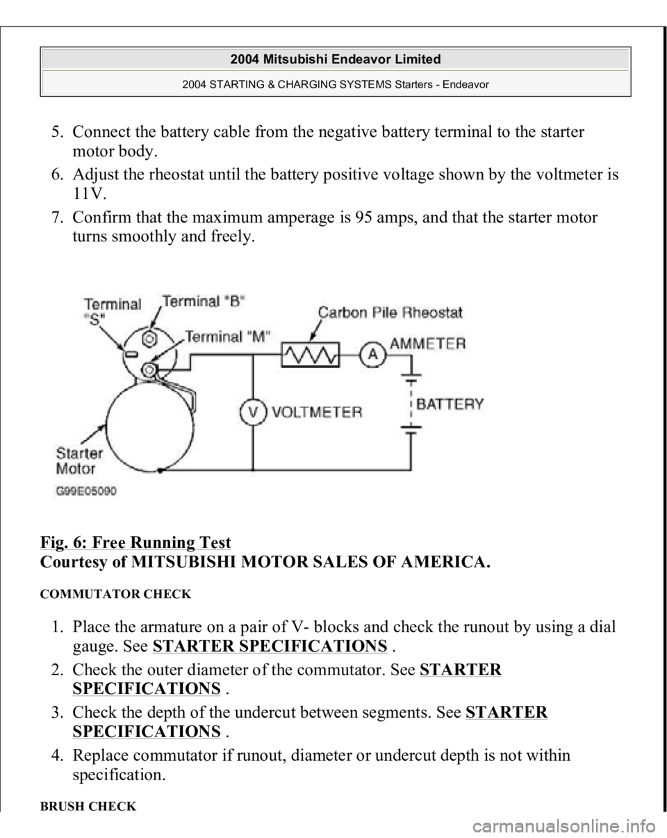
FREE RUNNING TEST 1. Place the starter motor in a vise equipped with soft jaws and connect a fully-
charged 12-volt battery to starter motor.
2. Connect a test ammeter (100-ampere scale) and carbon pile rheostat in series
between the positive battery terminal and starter motor terminal. See Fig. 6
.
3. Connect a voltmeter (15-volt scale) across the starter motor.
4. Rotate carbon
pile to full resistance
position.
2004 Mitsubishi Endeavor Limited
2004 STARTING & CHARGING SYSTEMS Starters - Endeavor
Page 3542 of 3870
5. Connect the battery cable from the negative battery terminal to the starter
motor body.
6. Adjust the rheostat until the battery positive voltage shown by the voltmeter is
11V.
7. Confirm that the maximum amperage is 95 amps, and that the starter motor
turns smoothly and freely.
Fig. 6: Free Running Test
Courtesy of MITSUBISHI MOTOR SALES OF AMERICA.
COMMUTATOR CHECK 1. Place the armature on a pair of V- blocks and check the runout by using a dial
gauge. See STARTER SPECIFICATIONS
.
2. Check the outer diameter of the commutator. See STARTER
SPECIFICATIONS
.
3. Check the depth of the undercut between segments. See STARTER
SPECIFICATIONS
.
4. Replace commutator if runout, diameter or undercut depth is not within
specification.
BRUSH CHECK
2004 Mitsubishi Endeavor Limited
2004 STARTING & CHARGING SYSTEMS Starters - Endeavor
Page 3543 of 3870
1. Check the brush for roughness of the surface that contacts the commutator and
check the brush length. Replace the brush holder if this measurement exceeds
the limit. The minimum limit is .28" (7.0 mm)
2. In the case contacting surface has been corrected or the brush has been
replaced, correct the contacting surface winding sandpaper around the
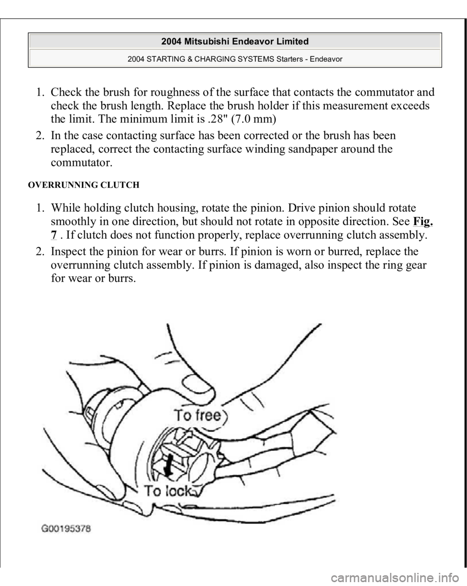
commutator. OVERRUNNING CLUTCH 1. While holding clutch housing, rotate the pinion. Drive pinion should rotate
smoothly in one direction, but should not rotate in opposite direction. See Fig.
7 . If clutch does not function properly, replace overrunning clutch assembly.
2. Inspect the pinion for wear or burrs. If pinion is worn or burred, replace the
overrunning clutch assembly. If pinion is damaged, also inspect the ring gear
for wear or burrs.
2004 Mitsubishi Endeavor Limited
2004 STARTING & CHARGING SYSTEMS Starters - Endeavor
Page 3544 of 3870
Fig. 7: Checking Overrunning Clutc
h
Courtesy of KIA MOTORS AMERICA, INC.
FRONT & REAR BRACKET BUSHING CHECK Inspect the bushing for wear or burrs. If the bushing is worn or burred, replace the
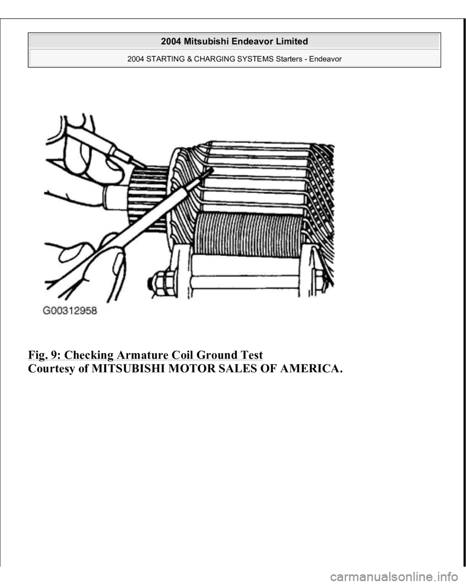
front bracket assembly or rear bracket assembly. ARMATURE CHECK 1. Check that the armature coil is not grounded.
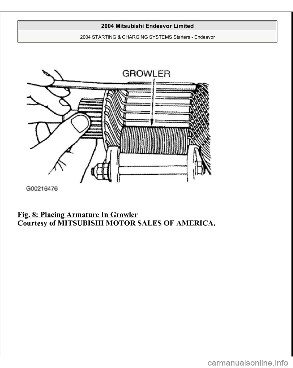
2. Place armature in a growler. See Fig. 8
.
3. Hold a thin steel blade parallel and just above while rotating the armature
slowly in the growler. A shorted armature will cause a blade to vibrate and
attract to the core. Replace the shorted armature.
4. Check the insulation between the armature coil cores and the commutator
segments. They are normal if there is no continuity. See Fig. 9
.
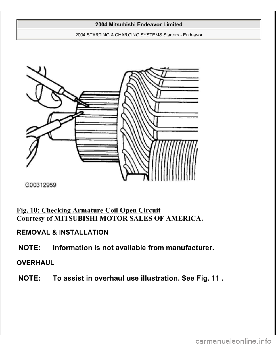
5. Check for continuity between the segments. The condition is normal if there is
continuit
y. See Fig. 10
.
2004 Mitsubishi Endeavor Limited
2004 STARTING & CHARGING SYSTEMS Starters - Endeavor
Page 3545 of 3870
Fig. 8: Placing Armature In Growler
Courtesy of MITSUBISHI MOTOR SALES OF AMERICA.
2004 Mitsubishi Endeavor Limited
2004 STARTING & CHARGING SYSTEMS Starters - Endeavor
Page 3546 of 3870
Fig. 9: Checking Armature Coil Ground Test
Courtesy of MITSUBISHI MOTOR SALES OF AMERICA.
2004 Mitsubishi Endeavor Limited
2004 STARTING & CHARGING SYSTEMS Starters - Endeavor
Page 3547 of 3870
Fig. 10: Checking Armature Coil Open Circuit
Courtesy of MITSUBISHI MOTOR SALES OF AMERICA.
REMOVAL & INSTALLATION
OVERHAUL NOTE: Information is not available from manufacturer.
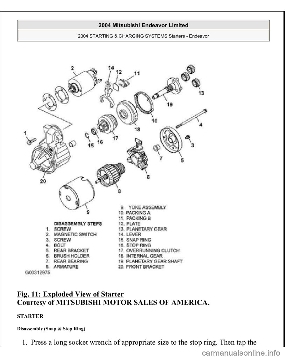
NOTE: To assist in overhaul use illustration. See Fig. 11
.
2004 Mitsubishi Endeavor Limited
2004 STARTING & CHARGING SYSTEMS Starters - Endeavor
Page 3548 of 3870
Fig. 11: Exploded View of Starter
Courtesy of MITSUBISHI MOTOR SALES OF AMERICA.
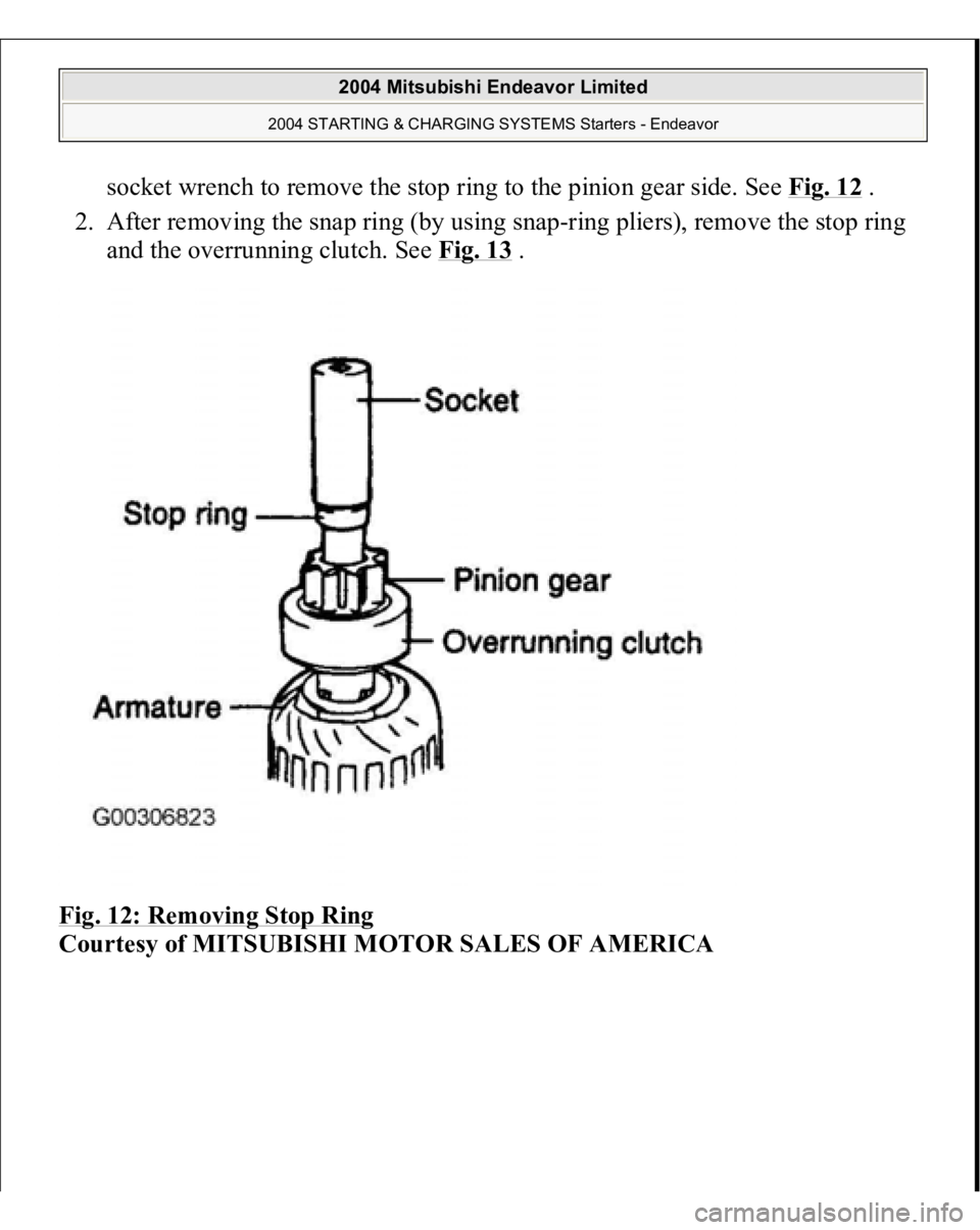
STARTER Disassembly (Snap & Stop Ring) 1. Press a lon
g socket wrench of a
ppropriate size to
the sto
p rin
g. Then ta
p the
2004 Mitsubishi Endeavor Limited
2004 STARTING & CHARGING SYSTEMS Starters - Endeavor
Page 3549 of 3870
socket wrench to remove the stop ring to the pinion gear side. See Fig. 12
.
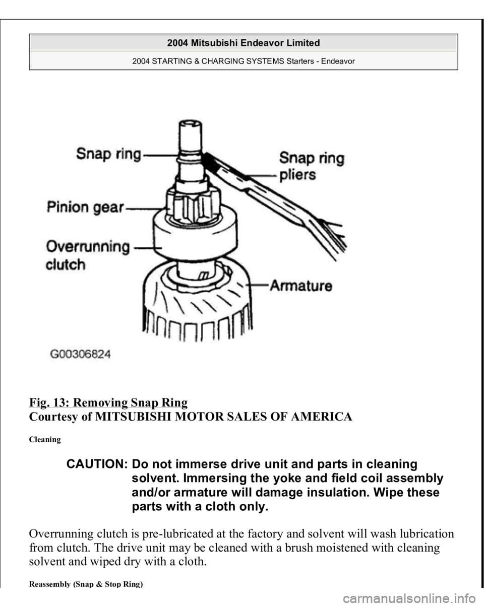
2. After removing the snap ring (by using snap-ring pliers), remove the stop ring
and the overrunning clutch. See Fig. 13
.
Fig. 12: Removing Stop Ring
Courtesy of MITSUBISHI MOTOR SALES OF AMERICA
2004 Mitsubishi Endeavor Limited
2004 STARTING & CHARGING SYSTEMS Starters - Endeavor
Page 3550 of 3870
Fig. 13: Removing Snap Ring
Courtesy of MITSUBISHI MOTOR SALES OF AMERICA
Cleaning Overrunning clutch is pre-lubricated at the factory and solvent will wash lubrication
from clutch. The drive unit may be cleaned with a brush moistened with cleaning
solvent and wiped dry with a cloth. Reassembl
y (Sna
p & Sto
p Rin
g)
CAUTION: Do not immerse drive unit and parts in cleaning
solvent. Immersing the yoke and field coil assembly
and/or armature will damage insulation. Wipe these
parts with a cloth only.
2004 Mitsubishi Endeavor Limited
2004 STARTING & CHARGING SYSTEMS Starters - Endeavor
Trending: height, camshaft, starter, check engine, Lift, cycle, audio
