MITSUBISHI GALANT 1989 Service Repair Manual
Manufacturer: MITSUBISHI, Model Year: 1989, Model line: GALANT, Model: MITSUBISHI GALANT 1989Pages: 1273, PDF Size: 37.62 MB
Page 1021 of 1273
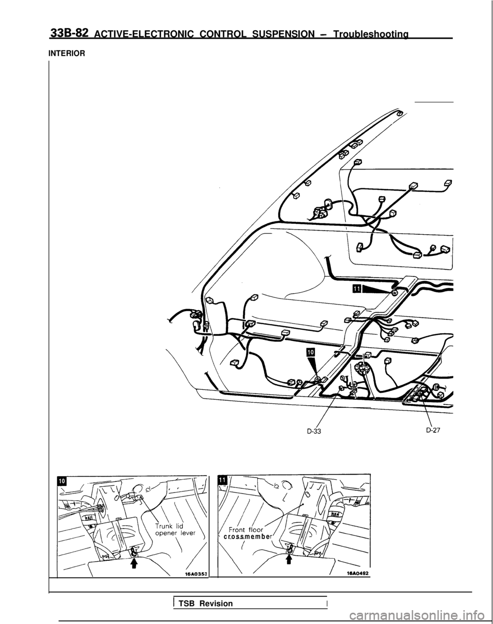
33B-82 ACTIVE-ELECTRONIC CONTROL SUSPENSION - Troubleshooting
INTERIOR
\\16AO353
’ crossmemb
e
\ //WA0492
1 TSB RevisionI
Page 1022 of 1273
ACTIVE-ELECTRONIC CONTROL
SUSPENSION - Troubleshooting 33B-83
D-21
TSB RevisionI
>
\D-24 36A0185
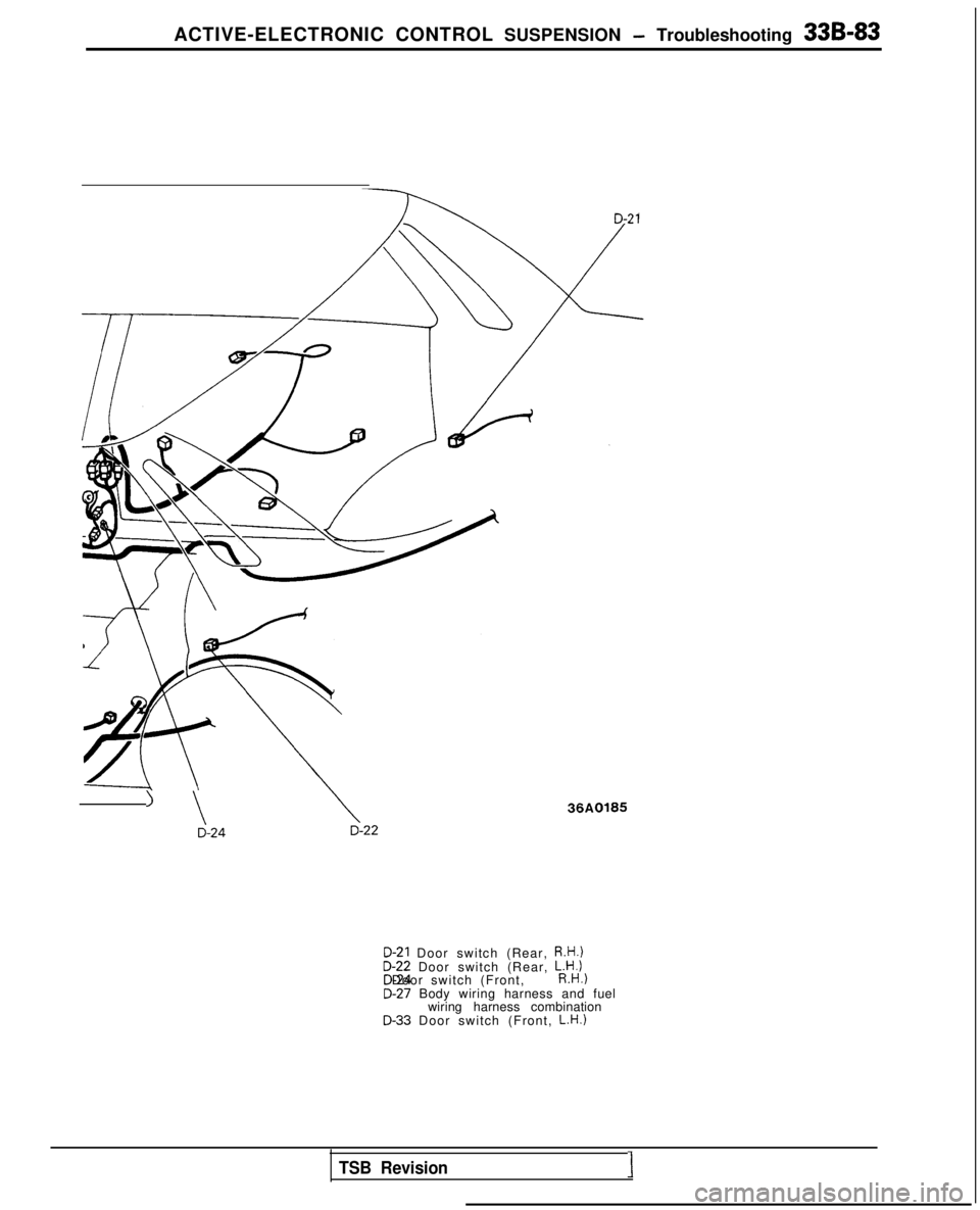
D-21 Door switch (Rear, R.H.)D-22 Door switch (Rear,
L.H.l
D-24 Door switch (Front, R.H.)D-27 Body wiring harness and fuel
wiring harness combination
D-33 Door switch (Front, L.H.)
Page 1023 of 1273
33B-84 ACTIVE-ELECTRONIC CONTROL SUSPENSION - Troubleshooting
IF
cUSTRUMENT
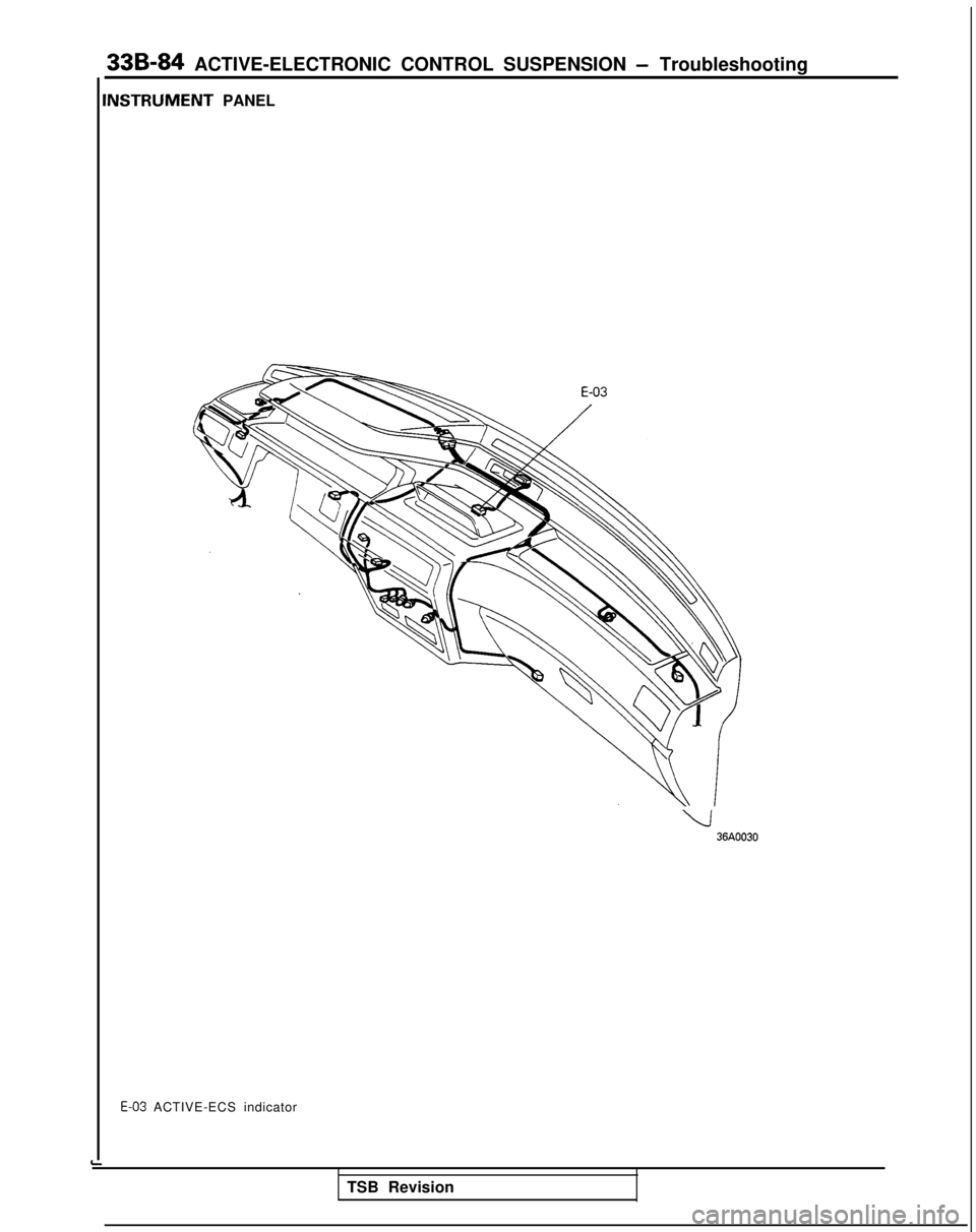
PANEL
Ll36AOO30
E-03 ACTIVE-ECS indicator
TSB Revision
Page 1024 of 1273
ACTIVE-ELECTRONIC CONTROL SUSPENSION - Troubleshooting 33B-85
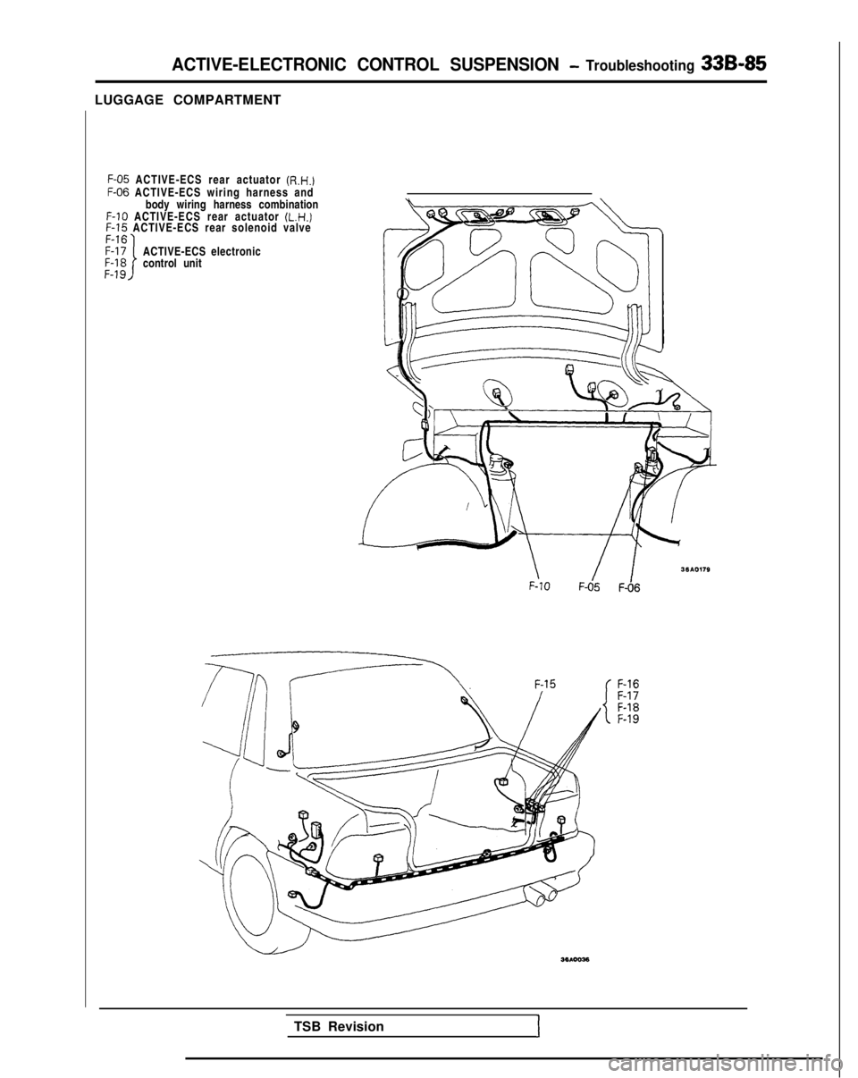
LUGGAGE COMPARTMENTF-05
ACTIVE-ECS rear actuator (R.H.)
F-06
ACTIVE-ECS wiring harness and
body wiring harness combination F-10
ACTIVE-ECS rear actuator (L.H.)
F-15
ACTIVE-ECS rear solenoid valve
ACTIVE-ECS electronic
control unit
\ F-101 IF-05
F-06
F-16
F-17
F-18
F-19
TSB Revision
1
Page 1025 of 1273
33B-86 ACTIVE-ELECTRONIC CONTROL SUSPENSION - ~~u,:~%i?:~~~~
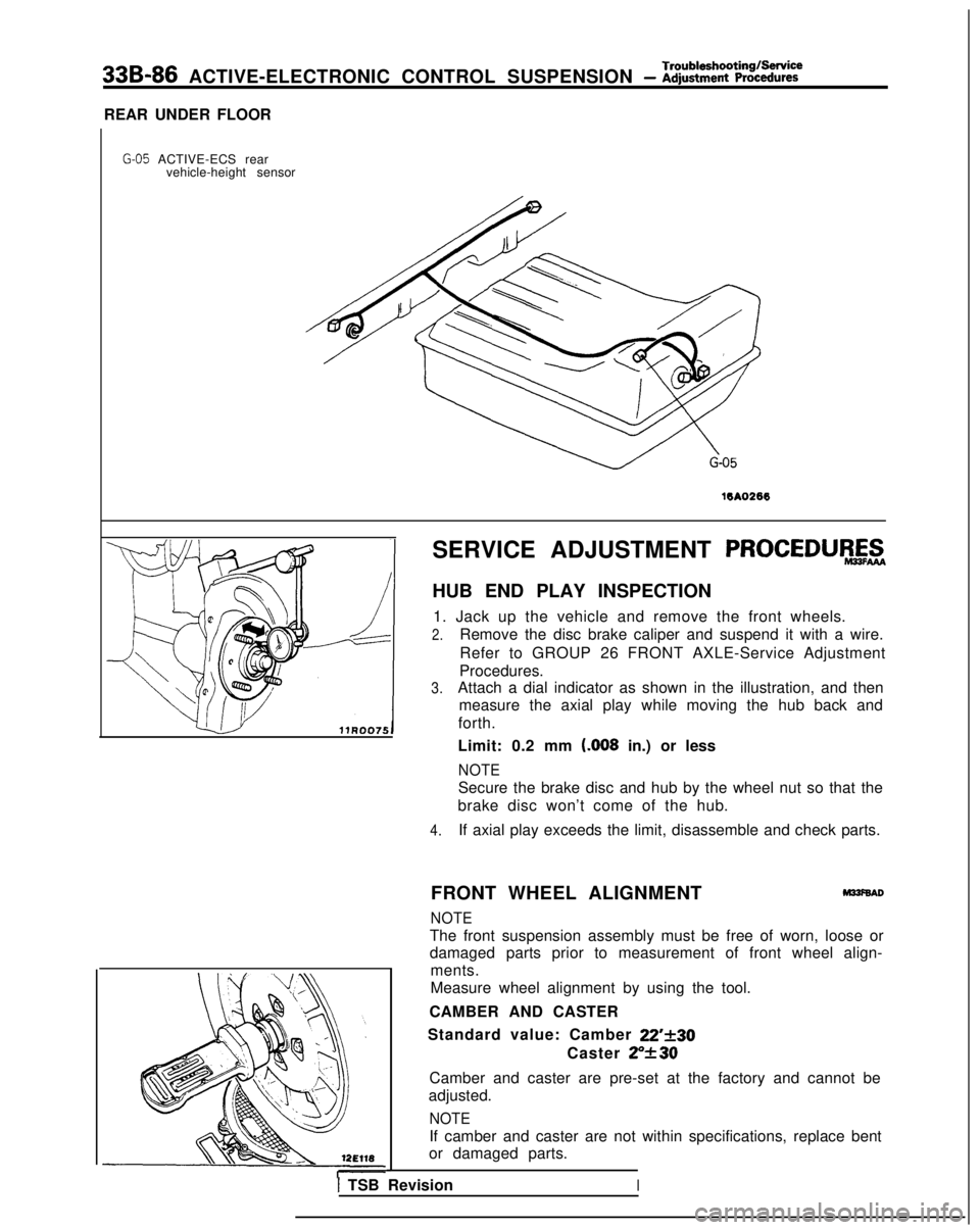
REAR UNDER FLOOR
G-05 ACTIVE-ECS rear vehicle-height sensor
16A0266
SERVICE ADJUSTMENT PROCEDURAZ
HUB END PLAY INSPECTION
1. Jack up the vehicle and remove the front wheels.
2.Remove the disc brake caliper and suspend it with a wire.
Refer to GROUP 26 FRONT AXLE-Service Adjustment
Procedures.
3.Attach a dial indicator as shown in the illustration, and then measure the axial play while moving the hub back and
forth.
Limit: 0.2 mm t.008
in.) or less
NOTE
Secure the brake disc and hub by the wheel nut so that the
brake disc won’t come of the hub.
4.If axial play exceeds the limit, disassemble and check parts.
FRONT WHEEL ALIGNMENT
M33f6AD
NOTE
The front suspension assembly must be free of worn, loose or
damaged parts prior to measurement of front wheel align- ments.
Measure wheel alignment by using the tool.
CAMBER AND CASTER
Standard value: Camber
22’f30
Caster ZY30
Camber and caster are pre-set at the factory and cannot be
adjusted.
NOTE
If camber and caster are not within specifications, replace bent
or damaged parts.
I TSB RevisionI
Page 1026 of 1273
ACTIVE-ELECTRONIC CONTROL SUSPENSIONService Adjustment- Procedures33B-87
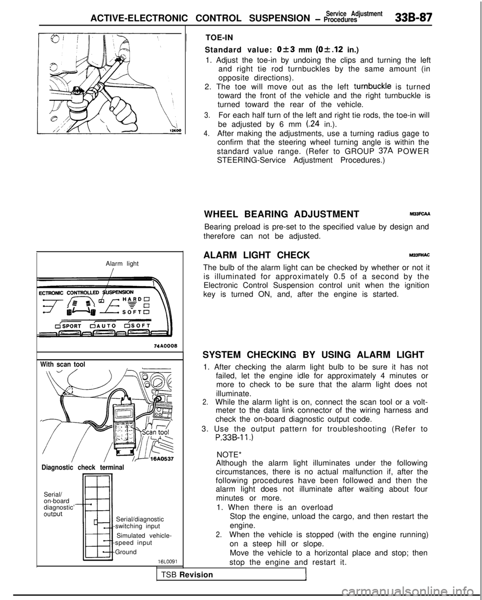
Alarm light
With scan tool
Diagnostic check terminal
Serial/
on-board
diagnostic’
outwt
TSB RevisionI
Serial/diagnostic
-switching input
Simulated vehicle-
-speed input
-Ground
16LOO91
!
TOE-IN
Standard value:
Ok3 mm (Of.12 in.)
1. Adjust the toe-in by undoing the clips and turning the left and right tie rod turnbuckles by the same amount (in
opposite directions).
2. The toe will move out as the left turnbuckle
is turned
toward the front of the vehicle and the right turnbuckle is
turned toward the rear of the vehicle.
3.For each half turn of the left and right tie rods, the toe-in will
be adjusted by 6 mm
(.24 in.).
4.After making the adjustments, use a turning radius gage to confirm that the steering wheel turning angle is within the
standard value range. (Refer to GROUP 37A
POWER
STEERING-Service Adjustment Procedures.)
WHEEL BEARING ADJUSTMENT
M33FcAA
Bearing preload is pre-set to the specified value by design and
therefore can not be adjusted.
ALARM LIGHT CHECK
MPFNAC
The bulb of the alarm light can be checked by whether or not it is illuminated for approximately 0.5 of a second by the
Electronic Control Suspension control unit when the ignition
key is turned ON, and, after the engine is started.
SYSTEM CHECKING BY USING ALARM LIGHT 1. After checking the alarm light bulb to be sure it has not failed, let the engine idle for approximately 4 minutes ormore to check to be sure that the alarm light does not
illuminate.
2.While the alarm light is on, connect the scan tool or a volt- meter to the data link connector of the wiring harness and
check the on-board diagnostic output code.
3. Use the output pattern for troubleshooting (Refer to
P.33B-11.)
NOTE*
Although the alarm light illuminates under the following
circumstances, there is no actual malfunction if, after the
following procedures have been followed and then the
alarm light does not illuminate after waiting about four
minutes or more.
1. When there is an overload Stop the engine, unload the cargo, and then restart the
engine.
2.When the vehicle is stopped (with the engine running)
on a steep hill or slope.Move the vehicle to a horizontal place and stop; then
stop the engine and restart it.
Page 1027 of 1273
338-88 ACTIVE-ELECTRONIC CONTROL SUSPENSION - ~~~%.,~Rment
With voltmeter
!//ii’12A0476
L
edge surface17AOOW(Right
Front) (Left
Rear)
12A0224 J3. When vehicle-height adjustments are made frequently
After stopping the engine, open the hood and allowthe compressor to cool; then restart the engine.
4. When the vehicle is driven on winding roads in the
mountains continuously for 18 minutes or longer.
To protect the return pump from damage, stop the
engine and then restart it.
*: Applicable to 1989 models only.
CHECKING BY ON-BOARD DIAGNOSTIC
1.Regardless of whether or not the alarm light is illuminated,
check the diagnostic output codes at the diagnostic termi-
nal.
2. If a malfunction code is output to the diagnostic terminal, perform the troubleshooting procedures according to the
output code.
NOTE
Diagnostic trouble codes are entered into the memory, even if
the ignition is at the OFF position, so that it is possible to check
for the existence of malfunctions that occurred previously.
NORMAL VEHICLE HEIGHT CHECK AND ADJUST-
MENT
1. Park the vehicle on a flat surface.
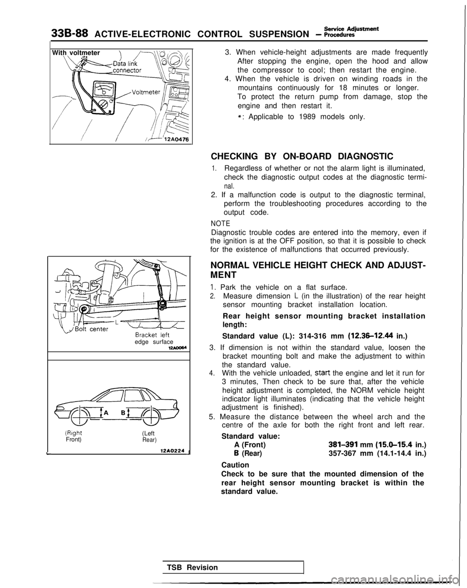
2.Measure dimension L (in the illustration) of the rear height
sensor mounting bracket installation location.
Rear height sensor mounting bracket installation
length:
Standard value (L): 314-316 mm (12.36-12.44 in.)
3. If dimension is not within the standard value, loosen the bracket mounting bolt and make the adjustment to within
the standard value.
4.With the vehicle unloaded, start
the engine and let it run for
3 minutes, Then check to be sure that, after the vehicle
height adjustment is completed, the NORM vehicle height
indicator light illuminates (indicating that the vehicle height
adjustment is finished).
5. Measure the distance between the wheel arch and the centre of the axle for both the right front and left rear.
Standard value: A (Front)
381391 mm (15.9-15.4 in.) 6
(Rear)357-367 mm (14.1-14.4 in.)
Caution
Check to be sure that the mounted dimension of the rear height sensor mounting bracket is within the
standard value.
TSB Revision
Page 1028 of 1273
ACTIVE-ELECTRONIC CONTROL SUSPENSION - ~~:i%,~:iustment 33B-89
Without
disconnecting
:he air tubing
Remaining
pressure
P =
120 kPa
(17 psi)
By disconnecting the
fir tubing
normal
condition
P ‘=.0
Front
tear (From 1990
model!
rmzIIconditlui
12AO281
Vehicle-height switch 6. If the vehicle height is not within the standard value,
loosen the turnbuckles of the front and rear height sensor
rods, and then make the adjustment by changing the
length of the rods. The vehicle height becomes higher
when the rods are lengthened.
Caution 1. Both the front and rear heights must be checked, because, even though only the front or the rear is
adjusted, the other height (rear or front) is also
changed.
2. The adjustments of the vehicle height must be made
while the engine is idling (vehicle stopped).
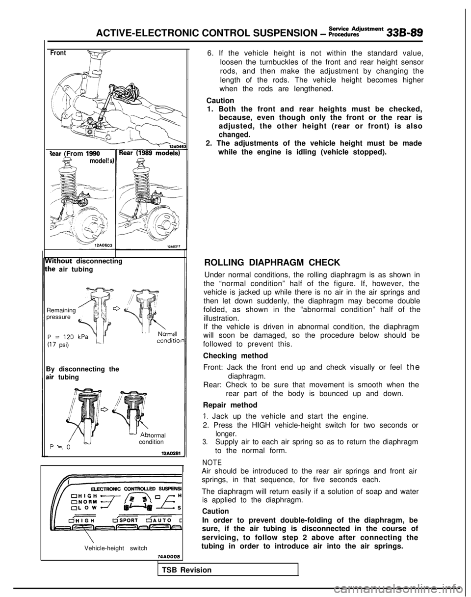
ROLLING DIAPHRAGM CHECK Under normal conditions, the rolling diaphragm is as shown in
the “normal condition” half of the figure. If, however, the
vehicle is jacked up while there is no air in the air springs and
then let down suddenly, the diaphragm may become double
folded, as shown in the “abnormal condition” half of the
illustration.
If the vehicle is driven in abnormal condition, the diaphragm
will soon be damaged, so the procedure below should be
followed to prevent this.
Checking method
Front: Jack the front end up and check visually or feel th
e
diaphragm.
Rear: Check to be sure that movement is smooth when the
rear part of the body is bounced up and down.
Repair method
1. Jack up the vehicle and start the engine.
2. Press the HIGH vehicle-height switch for two seconds or
longer.
3.Supply air to each air spring so as to return the diaphragm
to the normal form.
NOTE
Air should be introduced to the rear air springs and front air springs, in that sequence, for five seconds each.
The diaphragm will return easily if a solution of soap and water is applied to the diaphragm.
Caution
In order to prevent double-folding of the diaphragm, be
sure, if the air tubing is disconnected in the course of
servicing, to follow step 2 above after connecting the
tubing in order to introduce air into the air springs.
74AOOQ8
TSB Revision
Page 1029 of 1273
33B-90 ACTIVE-ELECTRONIC CONTROL SUSPENSION - i?:~i~:i@~~=“~
With vehicle speed simulatorClip attachment
posltion
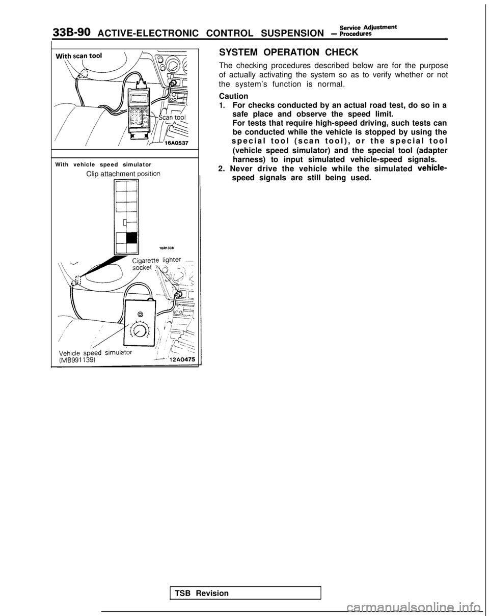
SYSTEM OPERATION CHECK
The checking procedures described below are for the purpose
of actually activating the system so as to verify whether or not
the system’s function is normal.
Caution
1.For checks conducted by an actual road test, do so in a
safe place and observe the speed limit.
For tests that require high-speed driving, such tests can
be conducted while the vehicle is stopped by using the
special tool (scan tool), or the special too
l
(vehicle speed simulator) and the special tool (adapter harness) to input simulated vehicle-speed signals.
2. Never drive the vehicle while the simulated
vehicle-
speed signals are still being used.
TSB Revision
Page 1030 of 1273
ACTIVE-ELECTRONIC CONTROL SUSPENSION - %ii%:justment 33B-91
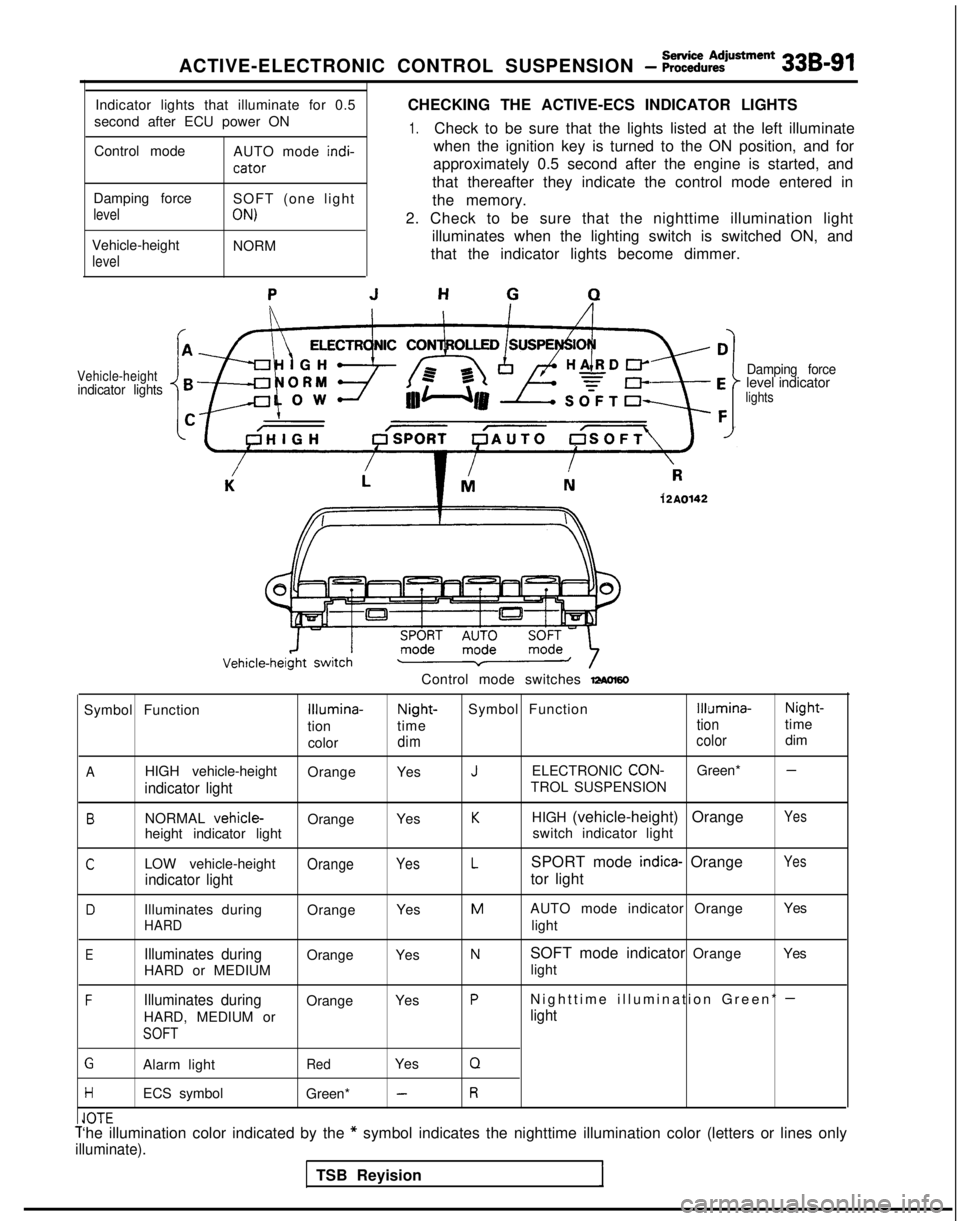
Indicator lights that illuminate for 0.5
second after ECU power ON
Control mode AUTO mode indi-
cator
CHECKING THE ACTIVE-ECS INDICATOR LIGHTS
1.Check to be sure that the lights listed at the left illuminate
when the ignition key is turned to the ON position, and for
approximately 0.5 second after the engine is started, and
that thereafter they indicate the control mode entered in
Damping force
level
Vehicle-height
level
SOFT (one light
ON)
NORM the memory.
2. Check to be sure that the nighttime illumination light illuminates when the lighting switch is switched ON, and
that the indicator lights become dimmer.
Vehicle-heightindicator lights Damping forcelevel indicatorlights
12A0142
Control mode switches -60
Symbol FunctionIllumina-Night-
Symbol FunctionIllumina- Night-
tion time
tiontime
color
dim colordim
AHIGH vehicle-height
OrangeYesJELECTRONIC CON-Green* -
indicator lightTROL SUSPENSION
BNORMAL vehicle-OrangeYesKHIGH (vehicle-height) OrangeYes
height indicator light switch indicator light
CLOW vehicle-heightOrangeYesLSPORT mode indica- OrangeYes
indicator lighttor light
DIlluminates during
OrangeYesMAUTO mode indicator Orange Yes
HARDlight
EIlluminates duringOrange
YesNSOFT mode indicator Orange Yes
HARD or MEDIUM light
FIlluminates duringOrange
YesPNighttime illumination Green* -
HARD, MEDIUM orlight
SOFT
GAlarm lightRedYesQ
HECS symbol
Green* -R
IA-r-Cl”lCT‘he illumination color indicated by the * symbol indicates the nighttime illumination color (letters or lines on\
ly
illuminate).
TSB Reyision