MITSUBISHI GALANT 1989 Service Repair Manual
Manufacturer: MITSUBISHI, Model Year: 1989, Model line: GALANT, Model: MITSUBISHI GALANT 1989Pages: 1273, PDF Size: 37.62 MB
Page 1031 of 1273
33B-92 ACTIVE-ELECTRONIC CONTROL SUSPENSION - ~~:%:?stment
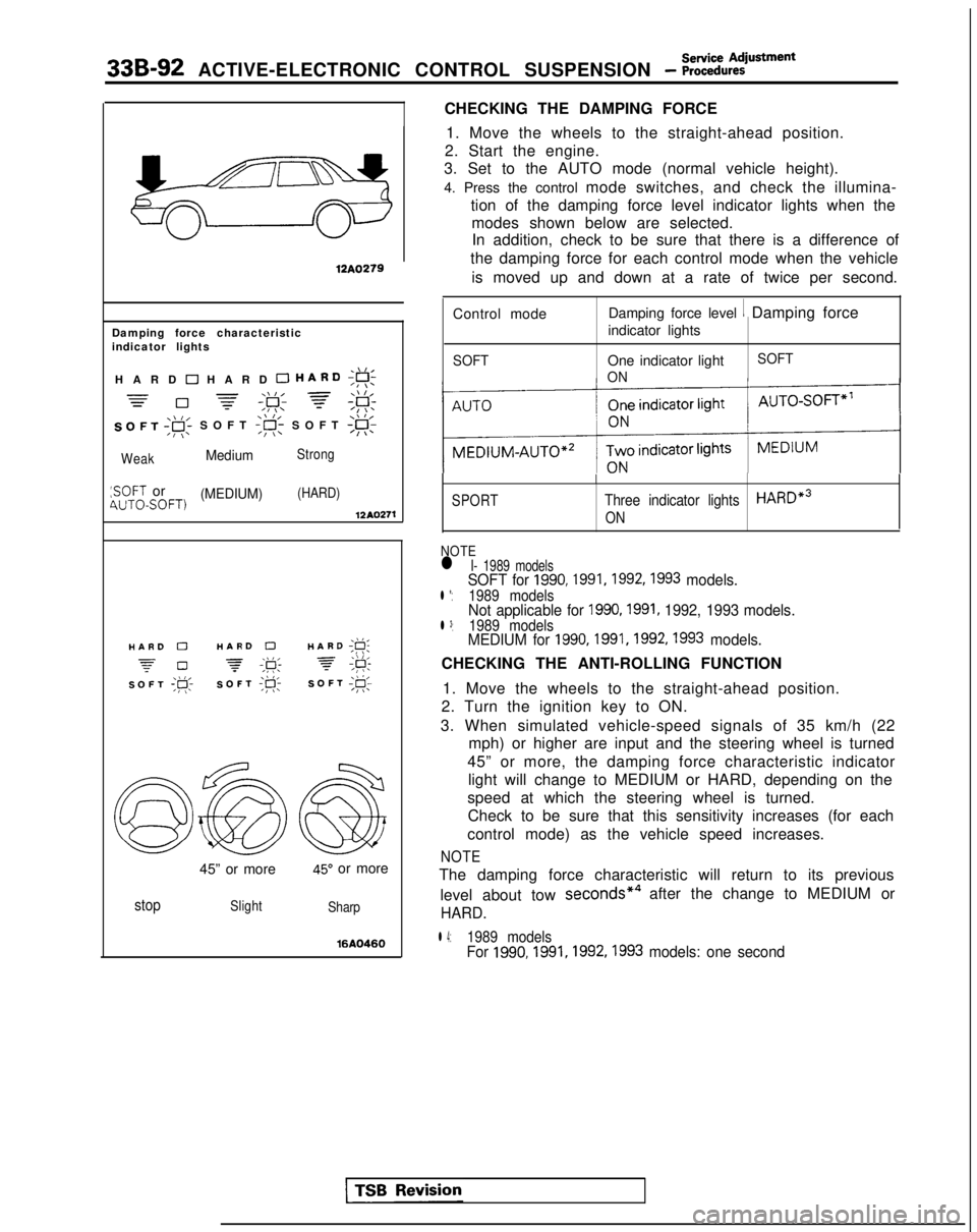
CHECKING THE DAMPING FORCE
12A0279
Damping force characteristic
indicator lights
,\,IHARD 0 HARD 0 HARD;g!;
=-\\I, =\\ l,=0 -=-,F; f;F:
SOFT ,gi SOFT
:SOFT or(MEDIUM)(HARD)4UTOSOFT)12AQ271
./I,HARD 0HARD 0HARD ;g;
z-0 -\k 3,\I I,SOFT ;p;SOFT ;R-SOFT I@;
45” or more45” or more
stopSlight
Sharp
16AQ460
1. Move the wheels to the straight-ahead position.
2. Start the engine.
3. Set to the AUTO mode (normal vehicle height).
4. Press the control mode switches, and check the illumina-
tion of the damping force level indicator lights when themodes shown below are selected.In addition, check to be sure that there is a difference of
the damping force for each control mode when the vehicle
is moved up and down at a rate of twice per second.
Control mode Damping force level
1 Damping force
indicator lights
SOFTOne indicator light
ON SOFT
SPORT
I
Three indicator lightsHARDe3
ON
NOTEl I- 1989 modelsSOFT for 1990,1991,1992,1993 models.l *:1989 modelsNot applicable for 1990,1991, 1992, 1993 models.l 3:1989 modelsMEDIUM for 1990,1991,1992,1993 models.
CHECKING THE ANTI-ROLLING FUNCTION
1. Move the wheels to the straight-ahead position.
2. Turn the ignition key to ON.
3. When simulated vehicle-speed signals of 35 km/h (22 mph) or higher are input and the steering wheel is turned
45” or more, the damping force characteristic indicator light will change to MEDIUM or HARD, depending on the
speed at which the steering wheel is turned. Check to be sure that this sensitivity increases (for each
control mode) as the vehicle speed increases.
NOTE
The damping force characteristic will return to its previous
level about tow seconds*4
after the change to MEDIUM or
HARD.
l 4:1989 modelsFor 1990,1991,1992,1993
models: one second
Page 1032 of 1273
Service AdjustmentACTIVE-ELECTRONIC CONTROL SUSPENSION - Procedures33B-93
\\ I/HARD ;g;
7 #
SOFT;#c
\\ I/HARD ;F;
7 ;&
SOFT;@;
I12AO399
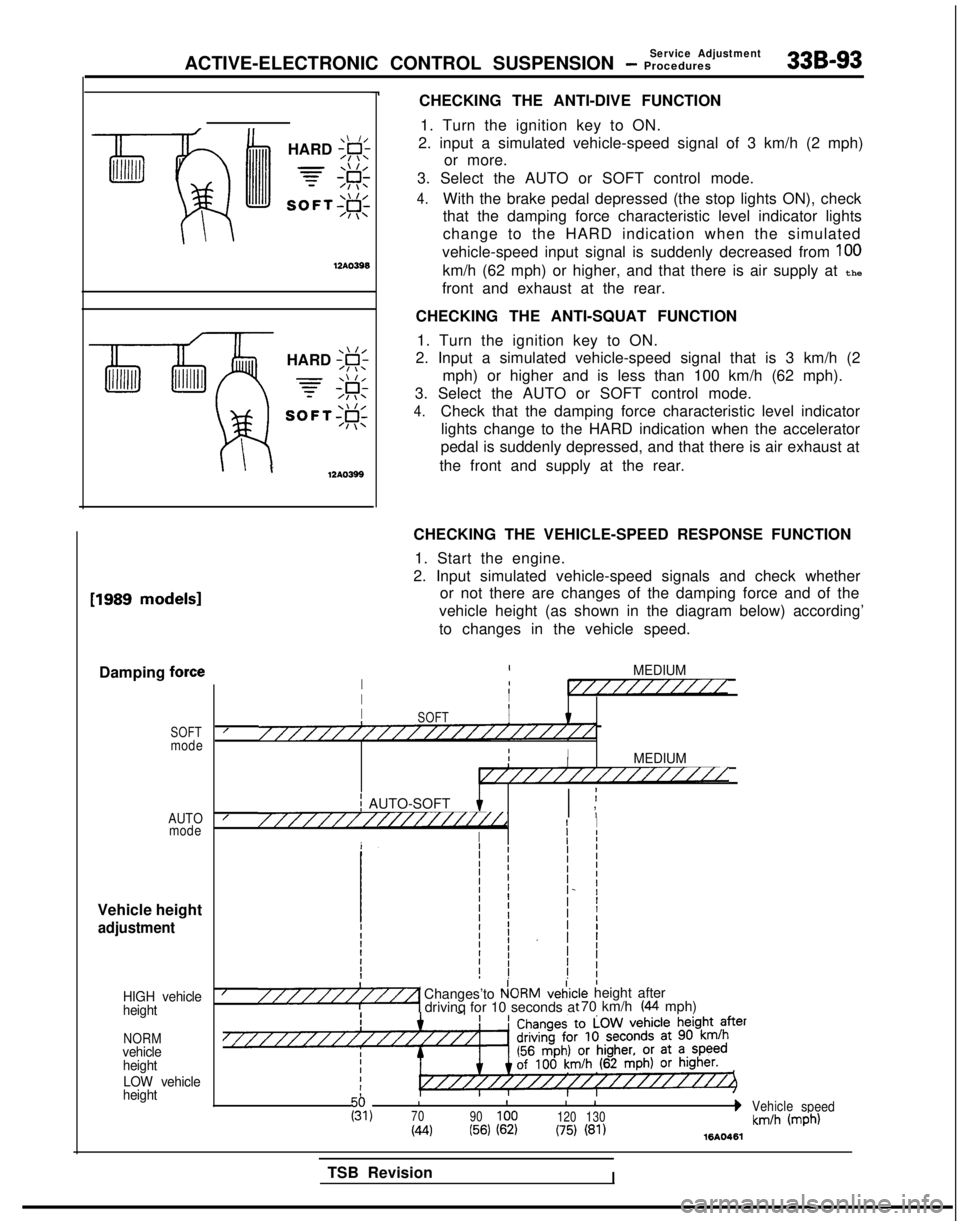
CHECKING THE ANTI-DIVE FUNCTION1. Turn the ignition key to ON.
2. input a simulated vehicle-speed signal of 3 km/h (2 mph) or more.
3. Select the AUTO or SOFT control mode.
4.With the brake pedal depressed (the stop lights ON), check
that the damping force characteristic level indicator lights
change to the HARD indication when the simulated
vehicle-speed input signal is suddenly decreased from
100
km/h (62 mph) or higher, and that there is air supply at the
front and exhaust at the rear.
CHECKING THE ANTI-SQUAT FUNCTION 1. Turn the ignition key to ON.
2. Input a simulated vehicle-speed signal that is 3 km/h (2
mph) or higher and is less than 100 km/h (62 mph).
3. Select the AUTO or SOFT control mode.
4.Check that the damping force characteristic level indicator lights change to the HARD indication when the accelerator
pedal is suddenly depressed, and that there is air exhaust at
the front and supply at the rear. [1989
models1
Damping force
SOFTmode
AUTO mode
Vehicle height
adjustment
HIGH vehicle
height
NORMvehicle
height
LOW vehicle
height
CHECKING THE VEHICLE-SPEED RESPONSE FUNCTION
1. Start the engine.
2. Input simulated vehicle-speed signals and check whether or not there are changes of the damping force and of the
vehicle height (as shown in the diagram below) according’
to changes in the vehicle speed.
IMEDIUMI1I//////////IIIII8SOFTI////////////////////////IIIIMEDIUMI////////////////
j AUTO-SOFT I ;I ,////////////////i//dI I
I
Ij I
I/Changes’to P!ORMveiic“““““1 drivinq for 10 seconds a:le height after t 70 km/h (44 mph)
III
I 1g,70
90100 120130bVehicle
speed
(44(56) (62)(75) (81)km/h (mph)1610461
TSB RevisionI
Page 1033 of 1273
![MITSUBISHI GALANT 1989 Service Repair Manual 33B-94 ACTIVE-ELECTRONIC CONTROL SUSPENSION - ;;:i%::iUsfment
[From 1990 models]
33A0552
Air tubeMB991 229
HIGH-PRESSURESWITCH(HIGH-PRESSURE
TANK SIDE) ACTUATION PRESSURE CHECK
1.Remove joint A of the MITSUBISHI GALANT 1989 Service Repair Manual 33B-94 ACTIVE-ELECTRONIC CONTROL SUSPENSION - ;;:i%::iUsfment
[From 1990 models]
33A0552
Air tubeMB991 229
HIGH-PRESSURESWITCH(HIGH-PRESSURE
TANK SIDE) ACTUATION PRESSURE CHECK
1.Remove joint A of the](/img/19/57312/w960_57312-1032.png)
33B-94 ACTIVE-ELECTRONIC CONTROL SUSPENSION - ;;:i%::iUsfment
[From 1990 models]
33A0552
Air tubeMB991 229
HIGH-PRESSURESWITCH(HIGH-PRESSURE
TANK SIDE) ACTUATION PRESSURE CHECK
1.Remove joint A of the yellow-marked air tube (for the front
air-supply valves) of the front solenoid valve assembly.
NOTE
Pull out.Press
12AO280
Joint A Removal is easier if the special tool is used to pull the air
tube out, and then a socket wrench is used for removal.
I
Page 1034 of 1273
ACTIVE-ELECTRONIC CONTROL SUSPENSION - ;;:i~%:?~~“~
33B-95
Adaptor E (MB991227)
Shut-off valve 12A.0350
iigh-pressure
witch
Air-pressure gauge (MB991075)
Adaptor C
(MB991 075.q
,daptor E (MB991226) /P-
3intH &‘xb
2.
3.
4.
5.
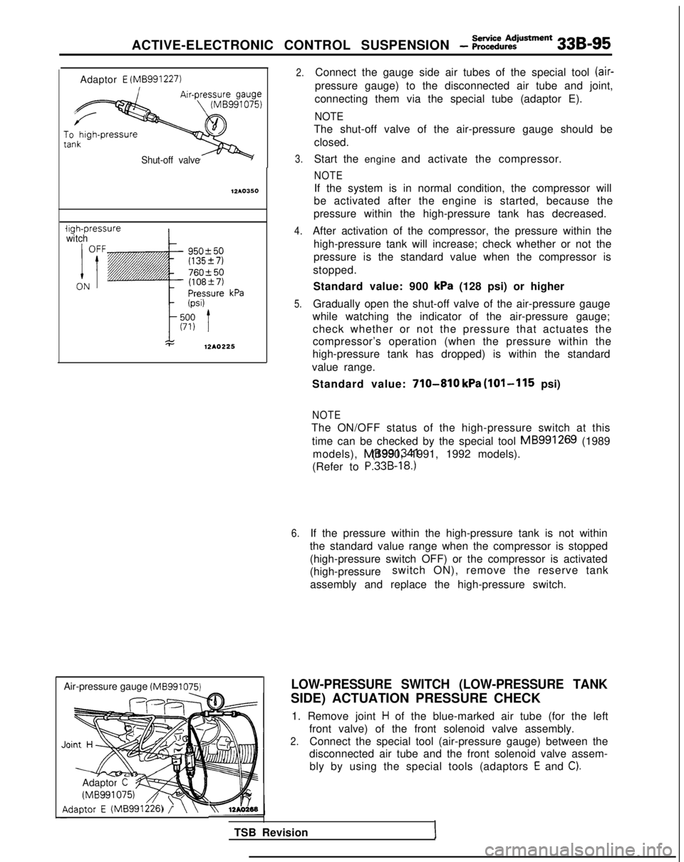
Connect the gauge side air tubes of the special tool (air-
pressure gauge) to the disconnected air tube and joint,
connecting them via the special tube (adaptor E).
NOTE
The shut-off valve of the air-pressure gauge should be closed.
Start the engine and activate the compressor.
NOTE
If the system is in normal condition, the compressor will
be activated after the engine is started, because the
pressure within the high-pressure tank has decreased.
After activation of the compressor, the pressure within the high-pressure tank will increase; check whether or not the
pressure is the standard value when the compressor is
stopped.
Standard value: 900
kPa (128 psi) or higher
Gradually open the shut-off valve of the air-pressure gauge
while watching the indicator of the air-pressure gauge; check whether or not the pressure that actuates the
compressor’s operation (when the pressure within the
high-pressure tank has dropped) is within the standard
value range.
Standard value:
710-810 kPa (101-115 psi)
NOTE
The ON/OFF status of the high-pressure switch at this time can be checked by the special tool MB991269
(1989
models), MB991341 (1990, 1991, 1992 models).
(Refer to
P.33B-18.)
6.If the pressure within the high-pressure tank is not within
the standard value range when the compressor is stopped
(high-pressure switch OFF) or the compressor is activated
(high-pressure switch ON), remove the reserve tank
assembly and replace the high-pressure switch.
LOW-PRESSURE SWITCH (LOW-PRESSURE TANK
SIDE) ACTUATION PRESSURE CHECK
1. Remove joint
H of the blue-marked air tube (for the left
front valve) of the front solenoid valve assembly.
2.Connect the special tool (air-pressure gauge) between the
disconnected air tube and the front solenoid valve assem-
bly by using the special tools (adaptors
E and C).
TSB RevisionI
Page 1035 of 1273
338-96
ACTIVE-ELECTRONIC CONTROL SUSPENSION - ;;~:;u~:iusment
Low-pressure
switch
PressurekPa (psi)
I
OFF
t
140 (20)
70 (10)
ON
12AO226
12A04P
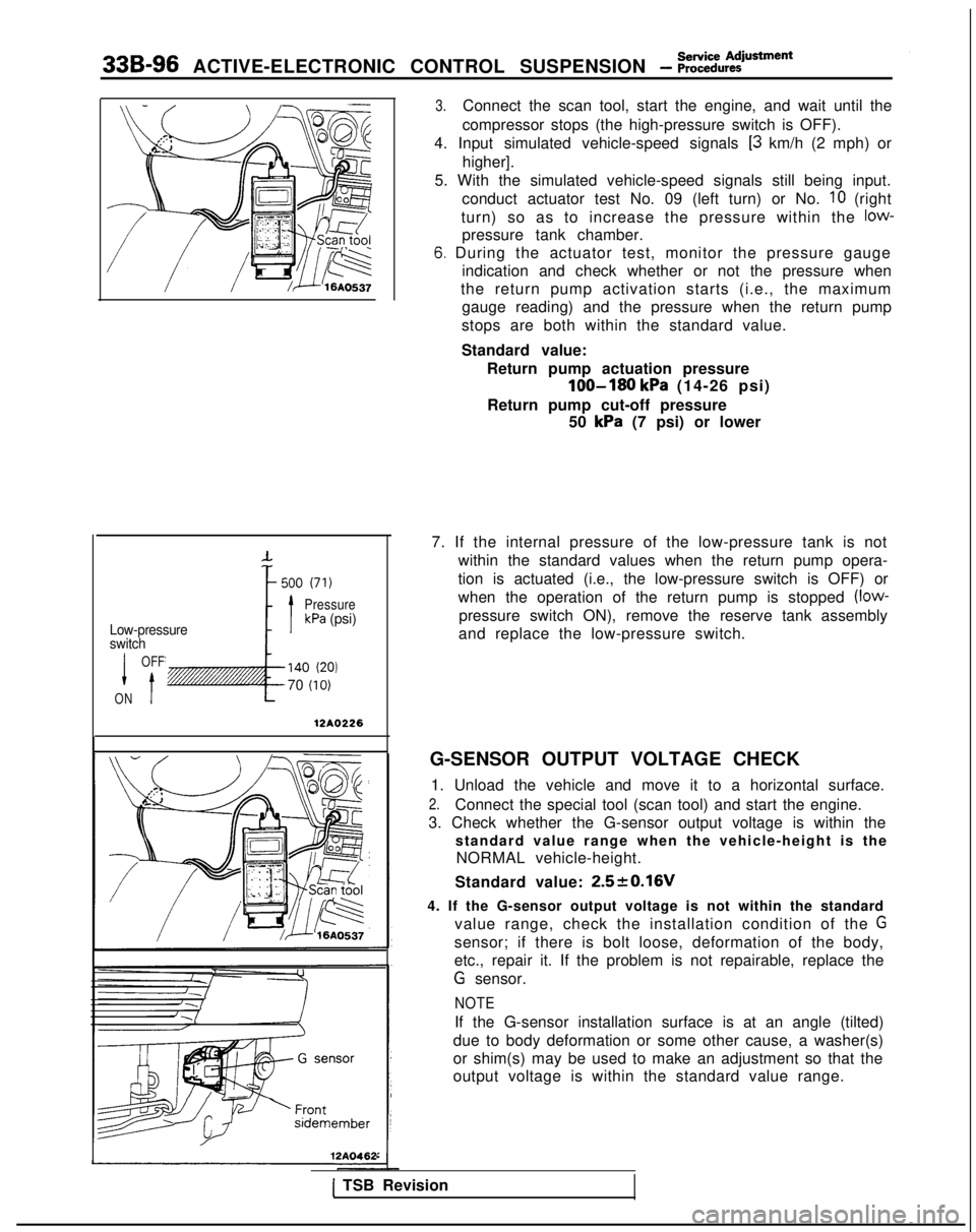
3.Connect the scan tool, start the engine, and wait until the
compressor stops (the high-pressure switch is OFF).
4. Input simulated vehicle-speed signals
[3 km/h (2 mph) or
higher].
5. With the simulated vehicle-speed signals still being input. conduct actuator test No. 09 (left turn) or No.
IO (right
turn) so as to increase the pressure within the
low-
pressure tank chamber.
6. During the actuator test, monitor the pressure gauge indication and check whether or not the pressure when
the return pump activation starts (i.e., the maximum gauge reading) and the pressure when the return pump
stops are both within the standard value.
Standard value: Return pump actuation pressure
loo-180 kPa (14-26 psi)
Return pump cut-off pressure 50
kPa (7 psi) or lower
7. If the internal pressure of the low-pressure tank is not within the standard values when the return pump opera-
tion is actuated (i.e., the low-pressure switch is OFF) or
when the operation of the return pump is stopped
(low-
pressure switch ON), remove the reserve tank assembly
and replace the low-pressure switch.
G-SENSOR OUTPUT VOLTAGE CHECK 1. Unload the vehicle and move it to a horizontal surface.
2.Connect the special tool (scan tool) and start the engine.
3. Check whether the G-sensor output voltage is within the standard value range when the vehicle-height is theNORMAL vehicle-height.
Standard value:
2.520.16V
4. If the G-sensor output voltage is not within the standard value range, check the installation condition of the
G
sensor; if there is bolt loose, deformation of the body,
etc., repair it. If the problem is not repairable, replace the
G sensor.
NOTE
If the G-sensor installation surface is at an angle (tilted)
due to body deformation or some other cause, a washer(s)
or shim(s) may be used to make an adjustment so that the
output voltage is within the standard value range.
1 TSB Revision
Page 1036 of 1273
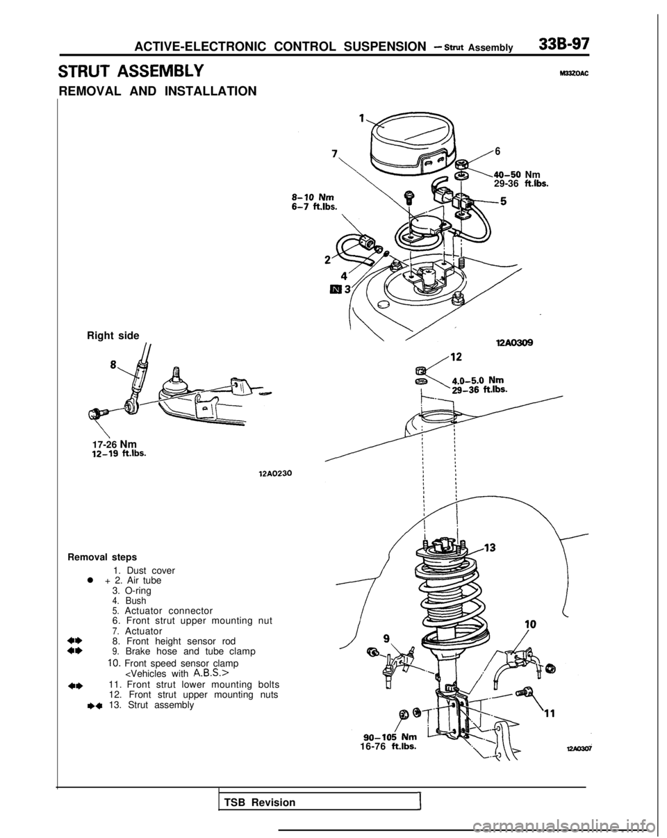
ACTIVE-ELECTRONIC CONTROL SUSPENSION - Strut Assembly33B-97
STRUT ASSEMBLYM33zOAC
REMOVAL AND INSTALLATION
6
40-50 Nm
29-36 ft.lbs.
Right side
17-26 Nm 12-19
ftlbs.
12A0230
Removal steps
1. Dust cover
l + 2. Air tube
3. O-ring
4.Bush5.Actuator connector
6. Front strut upper mounting nut
7.Actuator
4*8. Front height sensor rod::9.Brake hose and tube clamp
10. Front speed sensor clamp
4*11. Front strut lower mounting bolts12. Front strut upper mounting nuts
+a 13. Strut assembly
16-76
ft.lbs.
TSB Revision1
Page 1037 of 1273
33B-98ACTIVE-ELECTRONIC CONTROL SUSPENSION - Strut Assembly i
SERVICE POINTS OF REMOVALM33lBAE
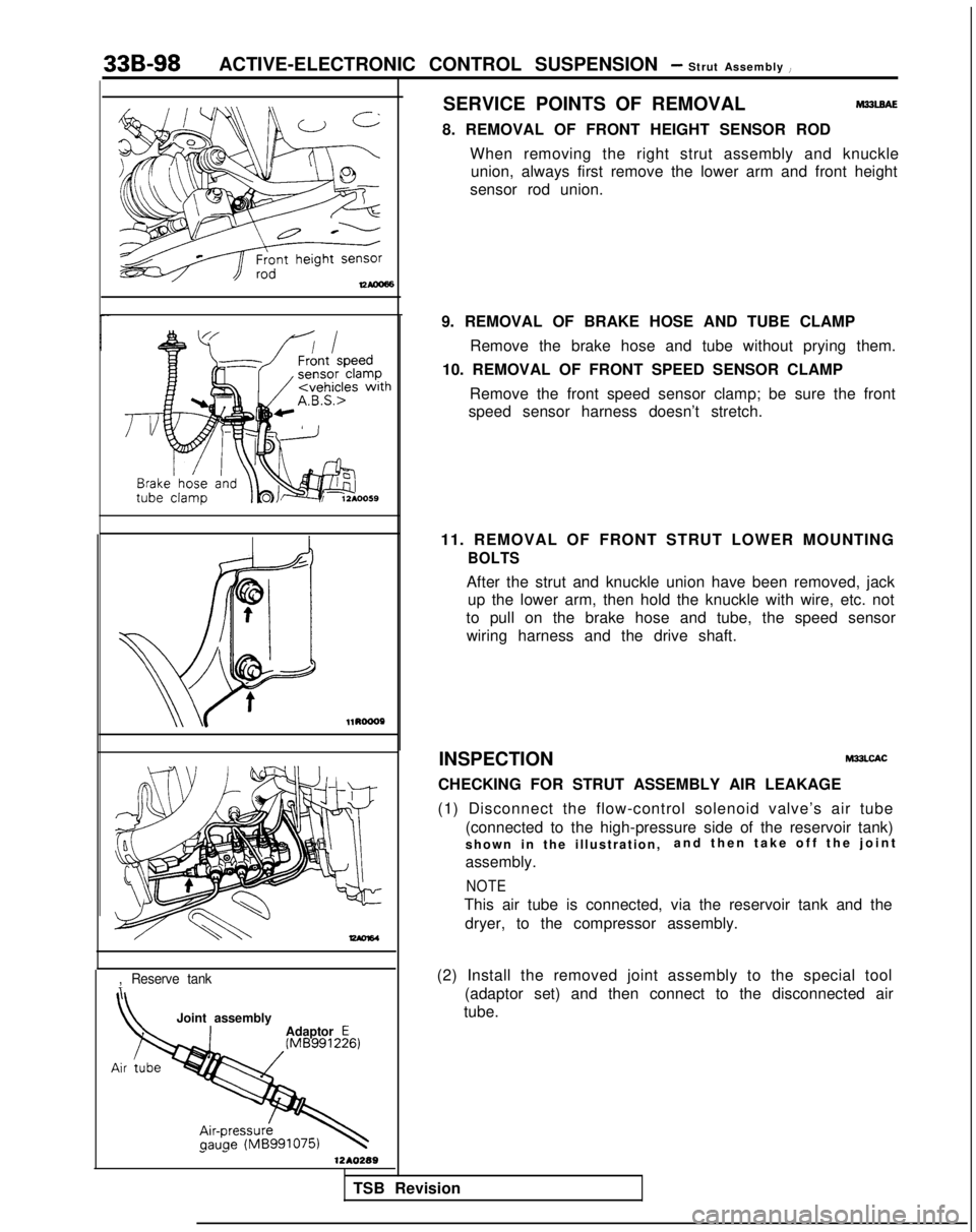
8. REMOVAL OF FRONT HEIGHT SENSOR RODWhen removing the right strut assembly and knuckleunion, always first remove the lower arm and front height
sensor rod union. l1RoooP
-
,Reserve tank
Joint assembly
Adaptor E
1 -1210289
9. REMOVAL OF BRAKE HOSE AND TUBE CLAMP
Remove the brake hose and tube without prying them.
10. REMOVAL OF FRONT SPEED SENSOR CLAMP
Remove the front speed sensor clamp; be sure the front
speed sensor harness doesn’t stretch.
11. REMOVAL OF FRONT STRUT LOWER MOUNTING
BOLTS
After the strut and knuckle union have been removed, jack up the lower arm, then hold the knuckle with wire, etc. not
to pull on the brake hose and tube, the speed sensor wiring harness and the drive shaft.
INSPECTION
M33LCAC
CHECKING FOR STRUT ASSEMBLY AIR LEAKAGE
(1) Disconnect the flow-control solenoid valve’s air tube (connected to the high-pressure side of the reservoir tank)
shown in the illustration, and then take off the join
t
assembly.
NOTE
This air tube is connected, via the reservoir tank and the dryer, to the compressor assembly.
(2) Install the removed joint assembly to the special tool (adaptor set) and then connect to the disconnected air
tube.
TSB Revision
Page 1038 of 1273
ACTIVE-ELECTRONIC CONTROL SUSPENSION - Strut Assembly33B-99
12Ao291
Strutator
a
.
Front
12AO.0003
Apply rubber grease
WA0327
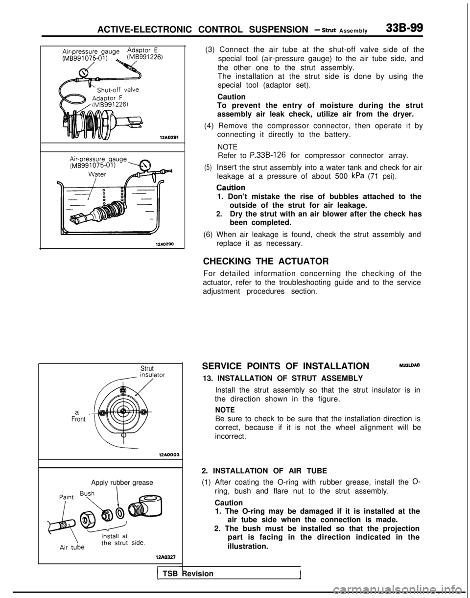
(3) Connect the air tube at the shut-off valve side of the
special tool (air-pressure gauge) to the air tube side, and
the other one to the strut assembly.
The installation at the strut side is done by using the special tool (adaptor set).
Caution
To prevent the entry of moisture during the strut
assembly air leak check, utilize air from the dryer.
(4) Remove the compressor connector, then operate it by connecting it directly to the battery.
NOTE
Refer to P.33B-126 for compressor connector array.
(5) Insert
the strut assembly into a water tank and check for air
leakage at a pressure of about 500
kPa (71 psi). Caiition
1. Don’t mistake the rise of bubbles attached to the outside of the strut for air leakage.
2.Dry the strut with an air blower after the check has
been completed.
(6) When air leakage is found, check the strut assembly and replace it as necessary.
CHECKING THE ACTUATOR For detailed information concerning the checking of the
actuator, refer to the troubleshooting guide and to the service
adjustment procedures section.
SERVICE POINTS OF INSTALLATION
M33LDAB
13. INSTALLATION OF STRUT ASSEMBLY Install the strut assembly so that the strut insulator is in
the direction shown in the figure.
NOTE
Be sure to check to be sure that the installation direction is
correct, because if it is not the wheel alignment will be
incorrect.
2. INSTALLATION OF AIR TUBE
(1) After coating the O-ring with rubber grease, install the
O-
ring, bush and flare nut to the strut assembly.
Caution 1. The O-ring may be damaged if it is installed at the
air tube side when the connection is made.
2. The bush must be installed so that the projection part is facing in the direction indicated in the
illustration.
1 TSB Revision
Page 1039 of 1273
33B-100ACTIVE-ELECTRONIC CONTROL SUSPENSION - Strut Assembly
(2) First insert the air tube until resistance is felt, and then push the tube in until the painted place on the air tube.
Caution
Air leakage may occur if the air tube connection is not
complete and secure.
C
ELECTRONIC CONTl
Vehicle-height switch
IISASSEMBLY
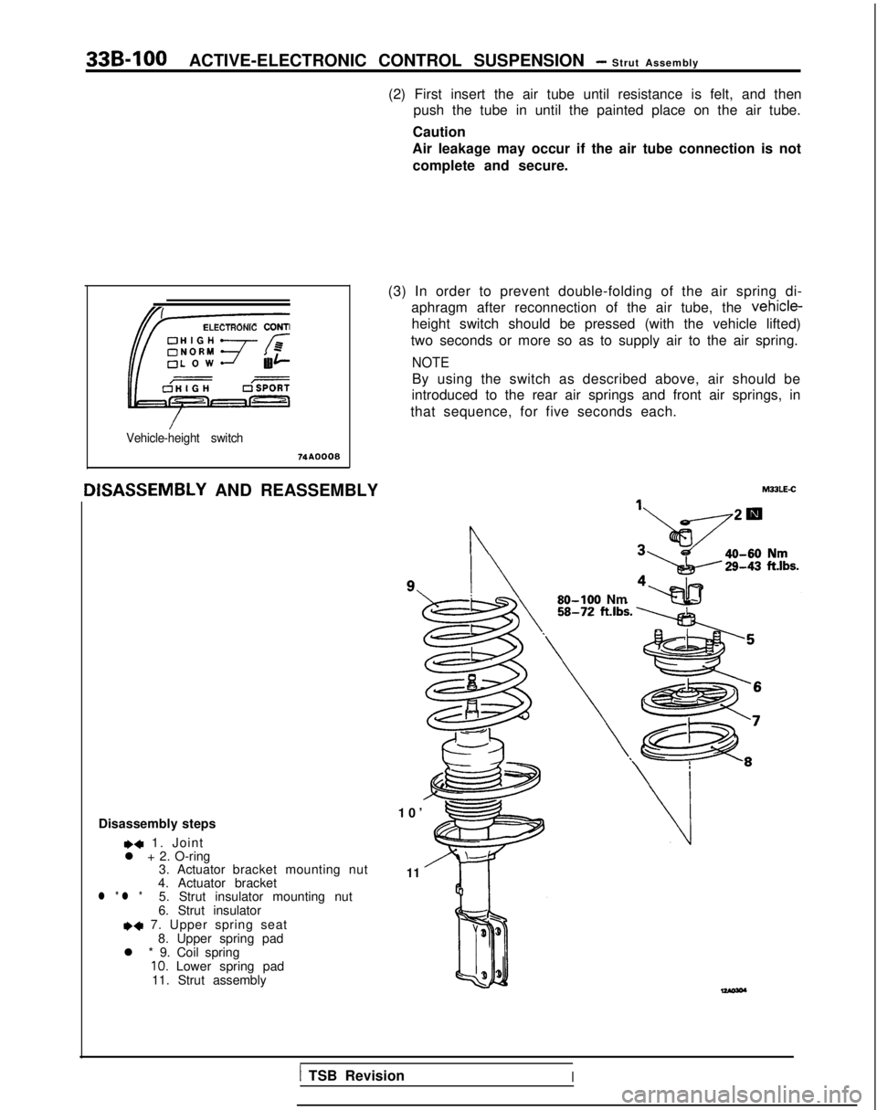
AND REASSEMBLY (3) In order to prevent double-folding of the air spring di-
aphragm after reconnection of the air tube, the vehicle-
height switch should be pressed (with the vehicle lifted)
two seconds or more so as to supply air to the air spring.
NOTE
By using the switch as described above, air should be
introduced to the rear air springs and front air springs, in
that sequence, for five seconds each.
Disassembly steps
,4 1. Joint
l + 2. O-ring 3. Actuator bracket mounting nut
4. Actuator bracket
l * l *5. Strut insulator mounting nut
6. Strut insulator
*+ 7. Upper spring seat 8. Upper spring pad
l * 9. Coil spring
10. Lower spring pad
11. Strut assembly
n
10
’
11 MULE-C
80-100 Nm
1 TSB RevisionI
Page 1040 of 1273
ACTIVE-ELECTRONIC CONTROL SUSPENSION - Strut Assembly33B-101
12AO275
12LO254
Strut insulator bearing12LOO34
12LO254
SERVICE POINTS OF DISASSEMBLYM23LFAD
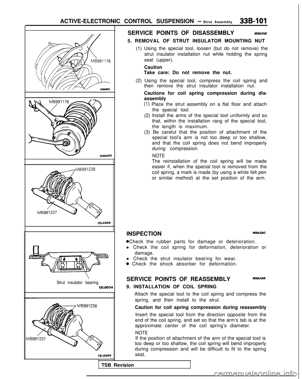
5. REMOVAL OF STRUT INSULATOR MOUNTING NUT
(1) Using the special tool, loosen (but do not remove) the strut insulator installation nut while holding the spring
seat (upper).
Caution
Take care: Do not remove the nut.
(2) Using the special tool, compress the coil spring and then remove the strut insulator installation nut.
Cautions for coil spring compression during dis- assembly
(1) Place the strut assembly on a flat floor and attach
the special tool.
(2) Install the arms of the special tool uniformly and so that, within the installation rang of the special tool,
the length is maximum.
(3) Be careful that the position of attachment of the special tool’s arm is not too deep or too shallow,
and that the coil spring does not bend improperly during compression.
NOTE
The reinstallation of the coil spring will be made easier if, when the special tool is removed from the
coil spring, a mark is made (by using a white felt pen
or similar method) at the set position of the arm.
INSPECTION MPLGAC
0 Check the rubber parts for damage or deterioration.
l Check the coil spring for deformation, deterioration or
damage.
l Check the strut insulator bearing for wear.
a Check the shock absorber for deformation.
SERVICE POINTS OF REASSEMBLY
M32LHAs
9. INSTALLATION OF COIL SPRING
TSB Revision Attach the special tool to the coil spring and compress the
spring, and then install to the strut.
Caution for coil spring compression during reassembly
Insert the special tool from the direction opposite from the
end of the coil spring, and set so that the arm’s tab is at the
approximate center of the coil spring’s diameter.
NOTE
If the position of attachment of the arm of the special tool is
too deep or too shallow, the coil spring will bend improperly
during compression and will be difficult to fit to the spring
seat.