MITSUBISHI GALANT 1989 Service Repair Manual
Manufacturer: MITSUBISHI, Model Year: 1989, Model line: GALANT, Model: MITSUBISHI GALANT 1989Pages: 1273, PDF Size: 37.62 MB
Page 1061 of 1273
33B-122 ACTIVE-ELECTRONIC CONTROL SUSPENSION - Reserve Tank
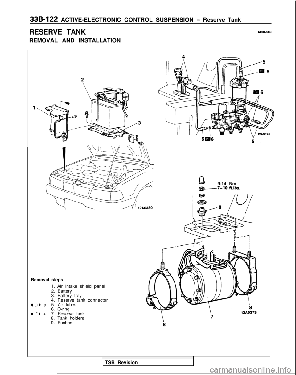
RESERVE TANK
REMOVAL AND INSTALLATION
M33ASAC
Removal steps
I, Air intake shield panel
2. Battery
3. Battery tray
4. Reserve tank connector
l ) l c5. Air tubes.I .6. O-ringl * l +7. Reserve tank
8. Tank holders
9. Bushes
6
=\ / 12AO395
9-14 Nm
@!+--7-10 ft.lbs.
TSB Revision
Page 1062 of 1273
IACTIVE-ELECTRONIC CONTROL SUSPENSION - Reserve Tank 33B-123
Air tube
12 :“b
\
w
ic ‘-0
IJoint assembly
MB991 22912A0280
12AO325
Grommet10P0081
Install to the body
beforehand
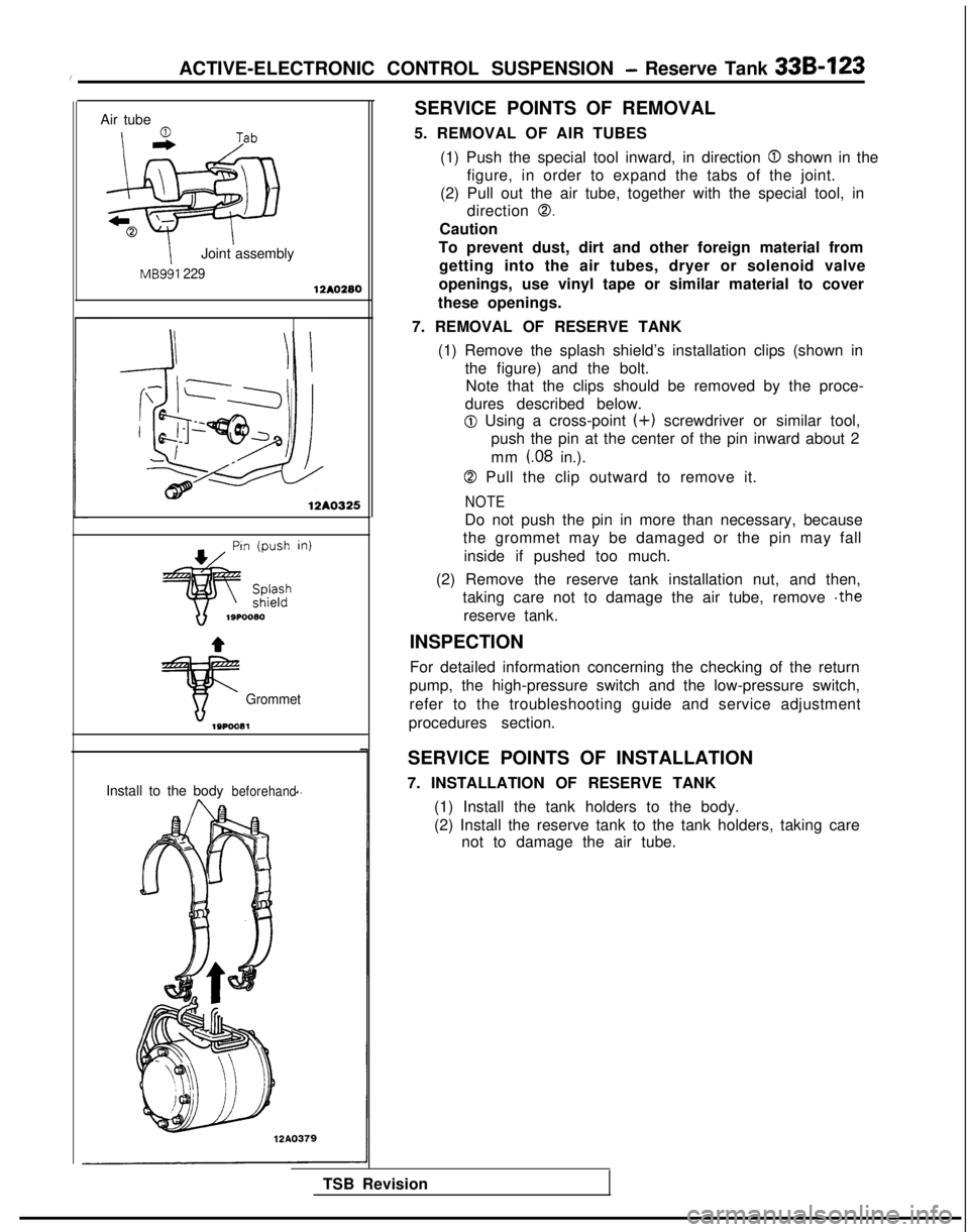
SERVICE POINTS OF REMOVAL
5. REMOVAL OF AIR TUBES (1) Push the special tool inward, in direction
0 shown in the
figure, in order to expand the tabs of the joint.
(2) Pull out the air tube, together with the special tool, in direction
0.
Caution
To prevent dust, dirt and other foreign material from getting into the air tubes, dryer or solenoid valve
openings, use vinyl tape or similar material to cover
these openings.
7. REMOVAL OF RESERVE TANK (1) Remove the splash shield’s installation clips (shown in the figure) and the bolt.Note that the clips should be removed by the proce-
dures described below.
@ Using a cross-point (+) screwdriver or similar tool,
push the pin at the center of the pin inward about 2
mm
(08 in.).
0 Pull the clip outward to remove it.
NOTE
Do not push the pin in more than necessary, because
the grommet may be damaged or the pin may fall
inside if pushed too much.
(2) Remove the reserve tank installation nut, and then, taking care not to damage the air tube, remove .the
reserve tank.
INSPECTION
For detailed information concerning the checking of the return
pump, the high-pressure switch and the low-pressure switch,
refer to the troubleshooting guide and service adjustment
procedures section.
SERVICE POINTS OF INSTALLATION
7. INSTALLATION OF RESERVE TANK (1) Install the tank holders to the body.
(2) Install the reserve tank to the tank holders, taking care not to damage the air tube.
TSB Revision
Page 1063 of 1273
33B-124 ACTIVE-ELECTRONIC CONTROL SUSPENSION - Reserve Tank
Splashshield
Grommet 12A0363
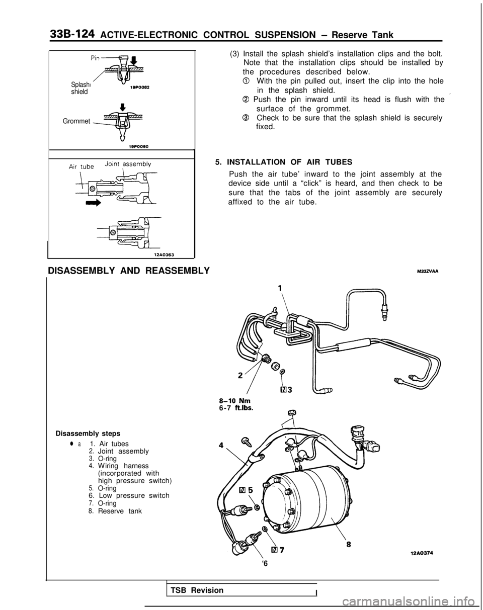
DISASSEMBLY AND REASSEMBLY (3) Install the splash shield’s installation clips and the bolt.
Note that the installation clips should be installed by
the procedures described below.
0With the pin pulled out, insert the clip into the hole in the splash shield.
0 Push the pin inward until its head is flush with the ’
surface of the grommet.
0Check to be sure that the splash shield is securely
fixed.
5. INSTALLATION OF AIR TUBES Push the air tube’ inward to the joint assembly at the
device side until a “click” is heard, and then check to be
sure that the tabs of the joint assembly are securely
affixed to the air tube. M33zvAA
8-10 Nm6-7 ft.lbs.
Disassembly steps
l a1. Air tubes2.Joint assembly3.O-ring4.W
iring harness
(incorporated with high pressure switch)
5.O-ring6. Low pressure switch7.O-ring8.Reserve tank
‘6
12A0374
TSB RevisionI
Page 1064 of 1273
ACTIVE-ELECTRONIC CONTROL SUSPENSION - ~~~,:B,:w,r 336-125
Paint
12Ao323
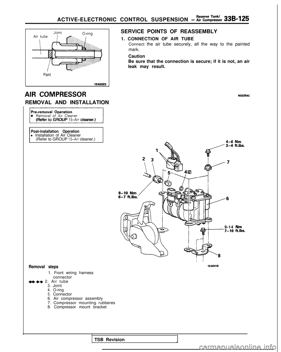
AIR COMPRESSOR
REMOVAL AND INSTALLATION
31(Refer to GROUP ISAir cleaner.)
Post-installation Operationl Installation of Air Cleaner
(Refer to GROUP 15-Air cleaner.)
Removal steps
1. Front wiring harness
connector
+* I)+ 2. Air tube3.Joint4.O-ring5.Connector
6. Air compressor assembly
7. Compressor mounting rubberes
8. Compressor mount bracket SERVICE POINTS OF REASSEMBLY
1. CONNECTION OF AIR TUBE Connect the air tube securely, all the way to the painted
mark.
Caution
Be sure that the connection is secure; if it is not, an air
leak may result.
: :
12AO418
9-14‘7-10
TSB Revision1
Page 1065 of 1273
33B-126ACTIVE-ELECTRONIC CONTROL SUSPENSION - Air compressor
L
MB991 075
w
I12AO443
12A0444
Exhaust solenoid valveJoint
Air iJbex ~~~~~~~~8,:,,.: :.:.:.:.: .,._,:.................:.
..........................................
i==Ja.................:.: . .......................
SERVICE POINTS OF REMOVAL
2. REMOVAL OF AIR TUBE Caution1. In order to prevent dust, dirt and other foreign material from getting into the air tube and air
compressor openings, cover these opening with
vinyl tape or similar material.
2. Be careful not to bend the air tubes.
INSPECTION
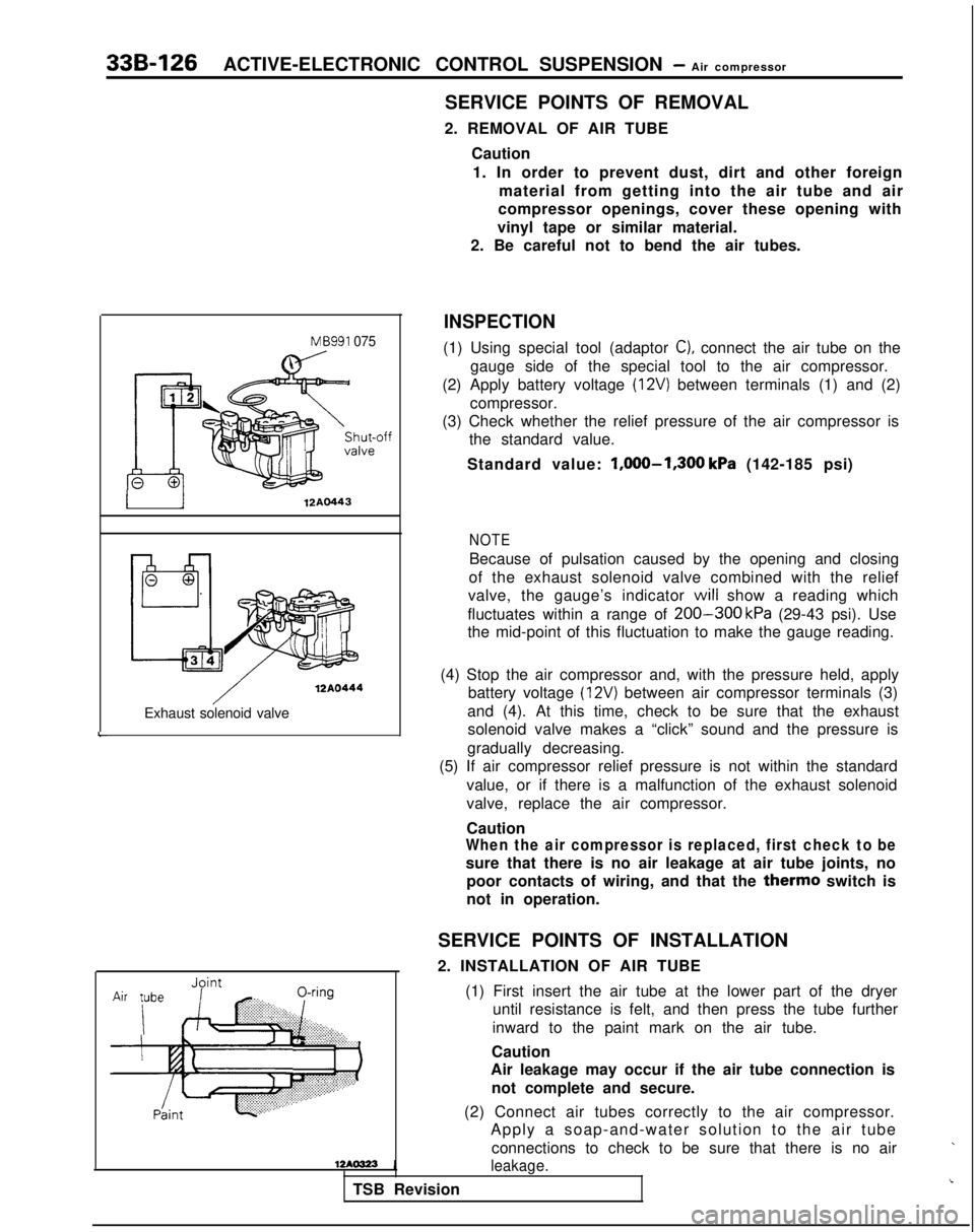
(1) Using special tool (adaptor C), connect the air tube on the
gauge side of the special tool to the air compressor.
(2) Apply battery voltage
(12V) between terminals (1) and (2)
compressor.
(3) Check whether the relief pressure of the air compressor is the standard value.
Standard value: l,OOO-1,300
kPa (142-185 psi)
NOTE
Because of pulsation caused by the opening and closing
of the exhaust solenoid valve combined with the relief
valve, the gauge’s indicator
will show a reading which
fluctuates within a range of
200-300 kPa (29-43 psi). Use
the mid-point of this fluctuation to make the gauge reading.
(4) Stop the air compressor and, with the pressure held, apply battery voltage
(12V) between air compressor terminals (3)
and (4). At this time, check to be sure that the exhaust solenoid valve makes a “click” sound and the pressure is
gradually decreasing.
(5) If air compressor relief pressure is not within the standard
value, or if there is a malfunction of the exhaust solenoid
valve, replace the air compressor.
Caution
When the air compressor is replaced, first check to be
sure that there is no air leakage at air tube joints, nopoor contacts of wiring, and that the
therm0 switch is
not in operation.
SERVICE POINTS OF INSTALLATION
2. INSTALLATION OF AIR TUBE
(1) First insert the air tube at the lower part of the dryeruntil resistance is felt, and then press the tube further
inward to the paint mark on the air tube.
Caution
Air leakage may occur if the air tube connection is
not complete and secure.
(2) Connect air tubes correctly to the air compressor. Apply a soap-and-water solution to the air tube
connections to check to be sure that there is no air
leakage.
TSB Revision
Page 1066 of 1273
Solenoid Valve andACTIVE-ELECTRONIC CONTROL SUSPENSION - Dryer33B-127
SOLENOID VALVE AND DRYERhl33ZPAC
REMOVAL AND INSTALLATION7-11 Nm
5-8
ft.lbs.
5-8 ft.lbs.
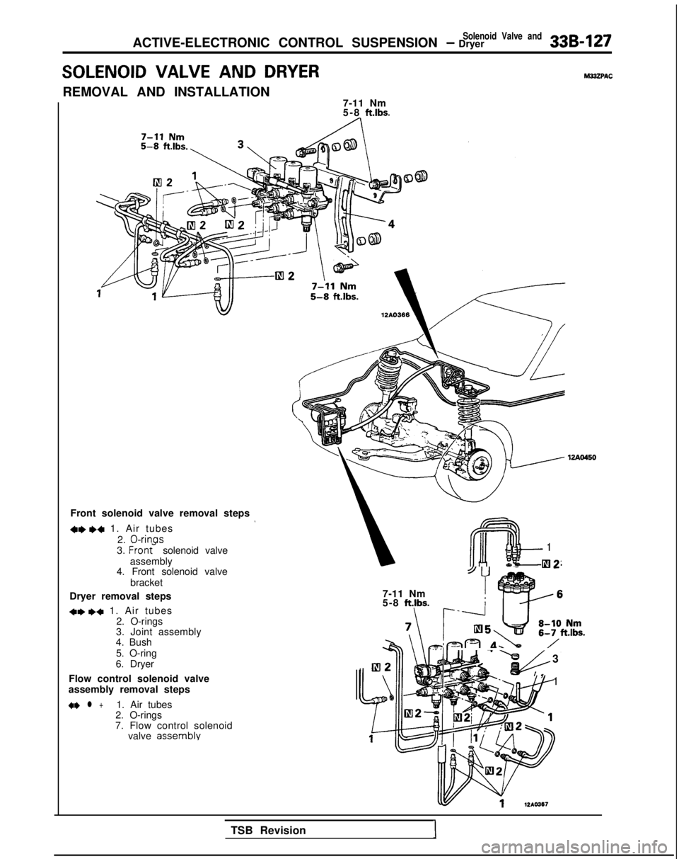
Front solenoid valve removal steps
+e I)+ 1. Air tubes
2.
0-rinas3. Fran<
solenoid valve
assembly
4. Front solenoid valve
bracket
Dryer removal steps
*I) I)+ 1. Air tubes 2. O-rings
3. Joint assembly
4. Bush
5. O-ring
6. Dryer
Flow control solenoid valve
assembly removal steps
*I) l +1. Air tubes
2. O-rings
7. Flow control solenoid valve
assembly
m
1
e-I-la2
7-11 Nm
5-8 ft.lbs.
u-b 3
f!&I ,1
TSB RevisionI
Page 1067 of 1273
33B-128 ACTIVE-ELECTRONIC CONTROL SUSPENSION - fi%?d Va’ve and
7-11 Nm5-8 ft.lbs.
4-6 Nm
3-4 ft.lbs.
Pre-removal Operation
I-im\.j -7
l Removal of Trunk Room Side Tr(Refer to GROUP 52-Trims.)
Air tube
0
\ e7” tiB991229
1210280
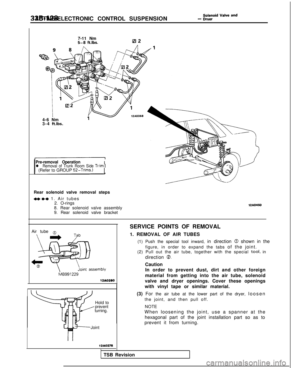
Rear solenoid valve removal steps
+e ,+ 1. Air tube
s
2. O-rings
8. Rear solenoid valve assembly
9. Rear solenoid valve bracket
12A0450
SERVICE POINTS OF REMOVAL
1. REMOVAL OF AIR TUBES
(1) Push the special tool inward, in direction
0 shown in the
figure, in order to expand the tabs of the joint.
(2) Pull out the air tube, together with the special
tool. in
direction
0.
Caution In order to prevent dust, dirt and other foreign
material from getting into the air tube, solenoid
valve and dryer openings. Cover these openings
with vinyl tape or similar material.
(3) For the air tube at the lower part of the dryer, loose
n
Hold to
prevent
turning.
the joint, and then pull off.
NOTE
When loosening the joint, use a spanner at the hexagonal part of the joint installation part so as to
prevent it from turning.
Joint
12AO278
TSB RevisionI
Page 1068 of 1273
ACTIVE-ELECTRONIC CONTROL SUSPENSION - &ttid Va’ve and 33B-129
12A0369
1 nql \- I E
II-II-II-II--~
G
DFIH12AO292
soap-and-water
solution.
INSPECTION
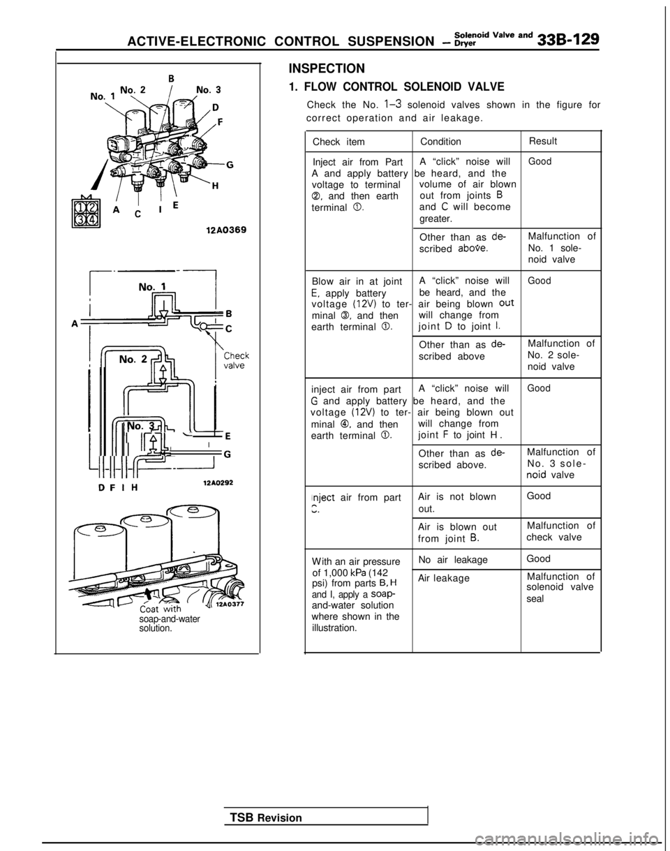
1. FLOW CONTROL SOLENOID VALVE
Check the No. l-3 solenoid valves shown in the figure for
correct operation and air leakage.
TSB Revision Check item
Condition Result
Inject air from Part A “click” noise will
Good
A and apply battery be
heard, and the
voltage to terminal volume of air blown
0, and then earthout from joints B
terminal 0.and C will become
greater.
Other than as
de-Malfunction of
scribed
abooe.No. 1 sole-
noid valve
Blow air in at joint A “click” noise will
Good
E. apply batterybe heard, and the
voltage (12V) to ter- air being blown out
minal 0, and then will change from
earth terminal
0.joint D to joint I.
Other than as de-Malfunction of
scribed above No. 2 sole-
noid valve
inject air from part A “click” noise will
Good
G and apply battery
be heard, and the
voltage
(12~) to ter- air being blown out
minal
@, and then will change from
earth terminal
0.joint F to joint H
.
Other than as
de-Malfunction of
scribed above. No.
3 sole
-
noid
valve
nject air from part Air is not blown GoodPir.out.
Air is blown out Malfunction of
from joint
B.check valve
W
ith an air pressure
No air leakage
Good
of 1,000
kPa (142 Malfunction of
psi) from parts 9, HAir leakage
solenoid valve
and I, apply a soap-seal
and-water solution
where shown in the illustration.
Page 1069 of 1273
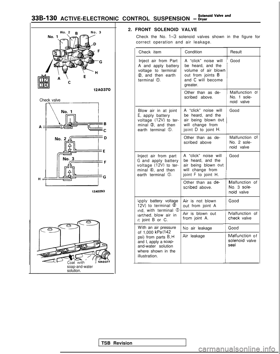
33B-130 ACTIVE-ELECTRONIC CONTROL SUSPENSION - ?Eid “=lve and
2. FRONT SOLENOID VALVECheck the No.
l-3 solenoid valves shown in the figure for
correct operation and air leakage.
No. 2
No.
3
Check item Result
Good
Condition
Inject air from Part
A and apply battery
voltage to terminal
0, and then earth
terminal
0.
A “click” noise will
be heard, and the
volume of air blow out from joints
B
and C will become
greater.
n
112A0370Malfunction oi
No. 1 sole-
noid valve
Other than as de-
scribed above.Check valve
A “click” noise will
be heard, and the
air being blown
ou’
will change from
joint
D to joint H.
GoodBlow air in at joint
E, apply battery
voltage
(12V) to ter-
minal
0. and then
earth terminal
0.
t I
H
=
Malfunction oi
No. 2 sole-
noid valve
Other than as de-
scribed above
A “click” noise will be heard, and the
air being blown
0u1
will change from
joint
F to joint H.
Other than as de-
xribed above.
Air is not blown
out from joint A
GoodInject air from part
G and apply battery
voltage
(12V) to ter-
minal
@, and then
earth terminal
0.
t
I=
i
r
(
Malfunction of
Yo. 3 sole-
loid valve
;ood
12AO293
4pply battery voltage
12V) to terminal 0
rnd. with terminal @
earthed, blow air in
rt joint B or C.
vlalfunction of :heck
valve
r
C
(
1
P
5c
Air is blown outYom joint A.
Vo air leakage
W
ith an air pressure
of 1,000
kPa (142
psi) from parts B, H
and I, apply a soap-and-water solution
where shown in the illustration.
;ood vlalfunction
of ;olenoid
valve ieal
lir leakage
soap-and-watersolution.
TSB Revision
Page 1070 of 1273
Solenoid Valve and
ACTIVE-ELECTRONIC CONTROL SUSPENSION - Dryer33B-131
3
F
‘G
\
12A0371
>
Rearpressure
sensor
l------i-l
12AO294
TSB Revision
-n
Coat withsoap-and-water
solution.
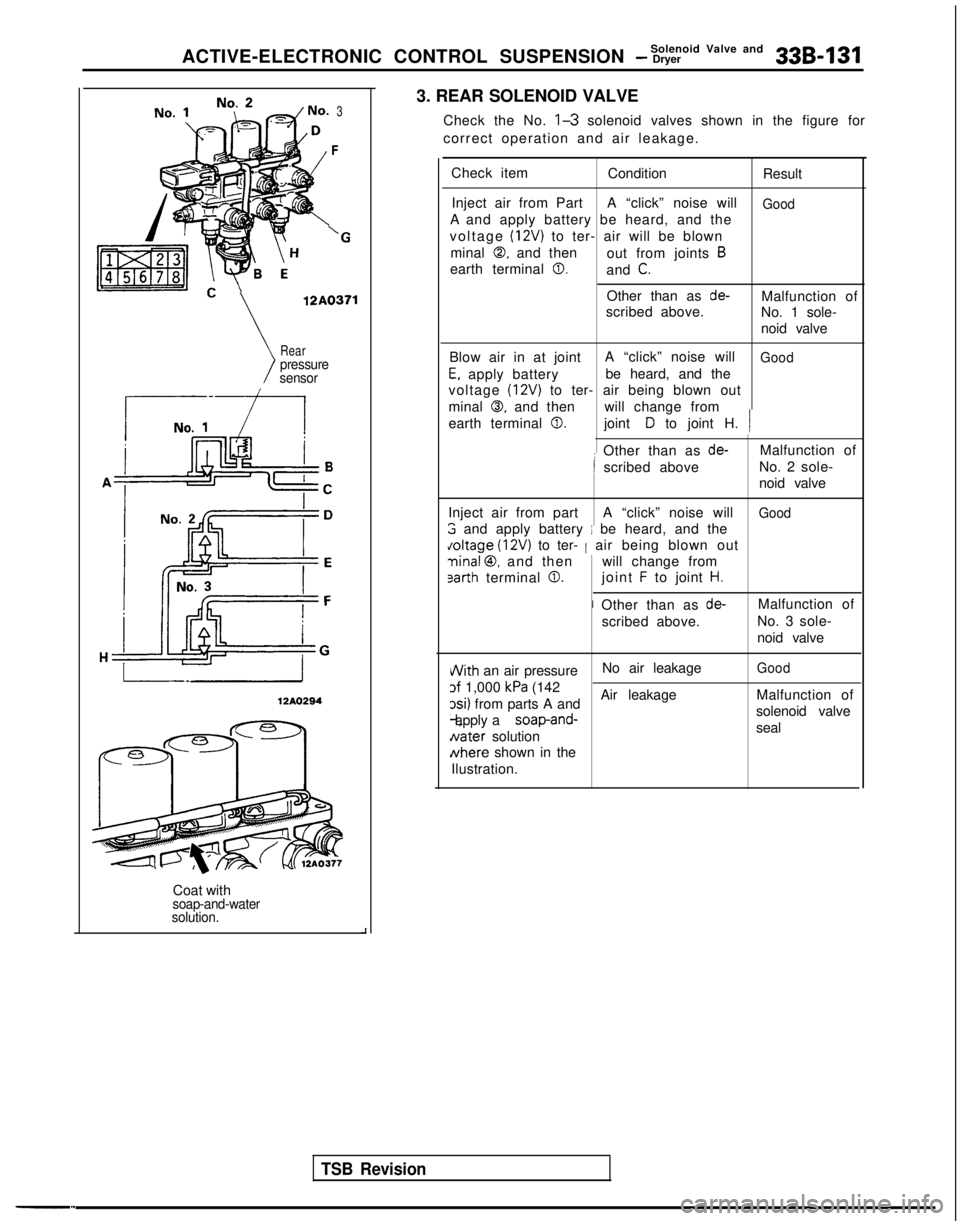
3. REAR SOLENOID VALVE
Check the No.
l-3 solenoid valves shown in the figure for
correct operation and air leakage.
Check item ConditionResult
Inject air from Part A “click” noise will
GoodA and apply battery be heard, and the
voltage
(12V) to ter- air will be blown
minal
0, and then out from joints B
earth terminal 0.and C.
Other than as de-Malfunction of
scribed above. No. 1 sole-
noid valve
Blow air in at joint A “click” noise will
Good
E, apply batterybe heard, and the
voltage
(12V) to ter- air being blown out
minal
0, and then will change from
earth terminal
0.joint D to joint H. /
: Other than as de-Malfunction of
I scribed above No. 2 sole-
noid valve
Inject air from part A “click” noise will
Good
3 and apply battery i be heard, and the doltage
(12V) to ter- 1 air being blown out
ninal @, and then will change from
sarth terminal 0.joint F to joint H.
I Other than as de-Malfunction of
scribed above. No. 3 sole-
noid valve
i/Vith an air pressureNo air leakageGood
of 1,000 kPa (142
xi) from parts A and Air leakage
Malfunction of -l, apply a
soap-and-solenoid valve
Nater
solution seal Nhere
shown in the
Ilustration.