MITSUBISHI GALANT 1989 Service Repair Manual
Manufacturer: MITSUBISHI, Model Year: 1989, Model line: GALANT, Model: MITSUBISHI GALANT 1989Pages: 1273, PDF Size: 37.62 MB
Page 1081 of 1273
33B-142 ACTIVE-ELECTRONIC CONTROL SUSPENSION - ACTIVE-ECS Relay
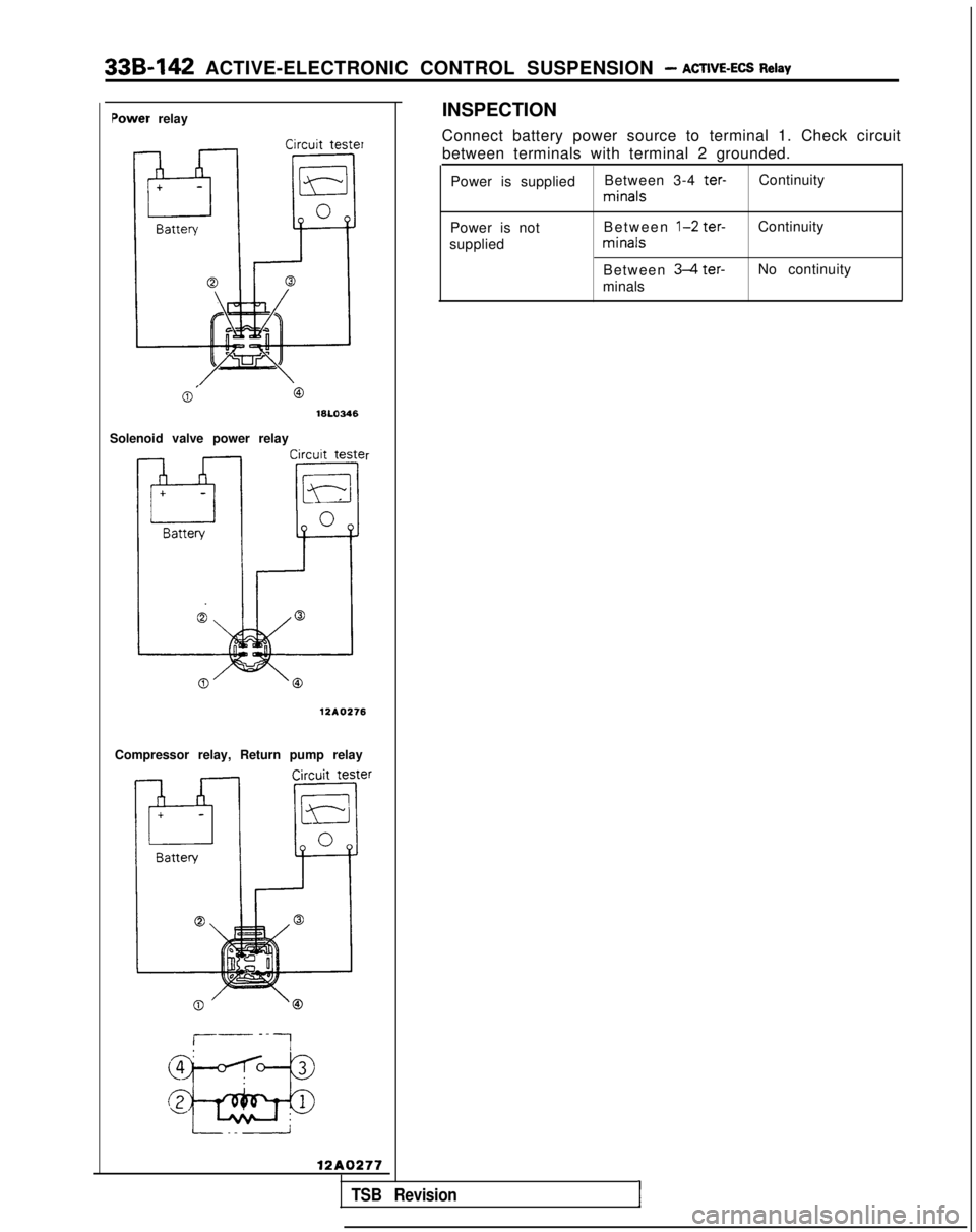
Power relay
Circuit tester
INSPECTION
Connect battery power source to terminal 1. Check circuit between terminals with terminal 2 grounded.
Power is supplied Between 3-4
ter-Continuity minals
Power is not
supplied Between
l-2 ter- minals
Between
34
ter-
minals Continuity
No continuity
0’16L0346
Solenoid valve power relay
r 12AO276
Compressor relay, Return pump relay
12A0277
TSB Revision1
Page 1082 of 1273
34-1
REAR
SUSPENSION
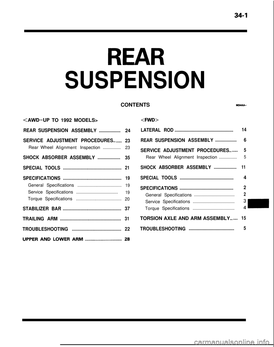
CONTENTSM%AA-
REARSUSPENSION
ASSEMBLY..................24
SERVICE ADJUSTMENT PROCEDURES..
.....23
Rear Wheel AlignmentInspection...............23
SHOCK
ABSORBERASSEMBLY...................35
SPECIAL TOOLS .............................................
21
SPECIFICATIONS.............................................19
GeneralSpecifications
..................................19
ServiceSpecifications ...................................19
TorqueSpecifications ...................................20
STABILIZER BAR .............................................
37
TRAILING ARM...............................................31
TROUBLESHOOTING......................................
22
UPPERANDLOWERARM............................28
LATERAL ROD.................................................14
REAR
SUSPENSIONASSEMBLY..................6
SERVICE ADJUSTMENT PROCEDURES.......5
Rear Wheel Alignment Inspection ...............5
SHOCKABSORBER
ASSEMBLY...................11
SPECIALTOOLS.............................................4
SPECIFICATIONS ............................................. 2
General Specifications
..................................2
Service
Specifications ...................................
TorqueSpecifications ...................................
TORSION AXLE AND ARM ASSEMBLY..
.... 15
TROUBLESHOOTING ......................................5
Page 1083 of 1273
34-2REAR SUSPENSION
SPECIFICATIONS
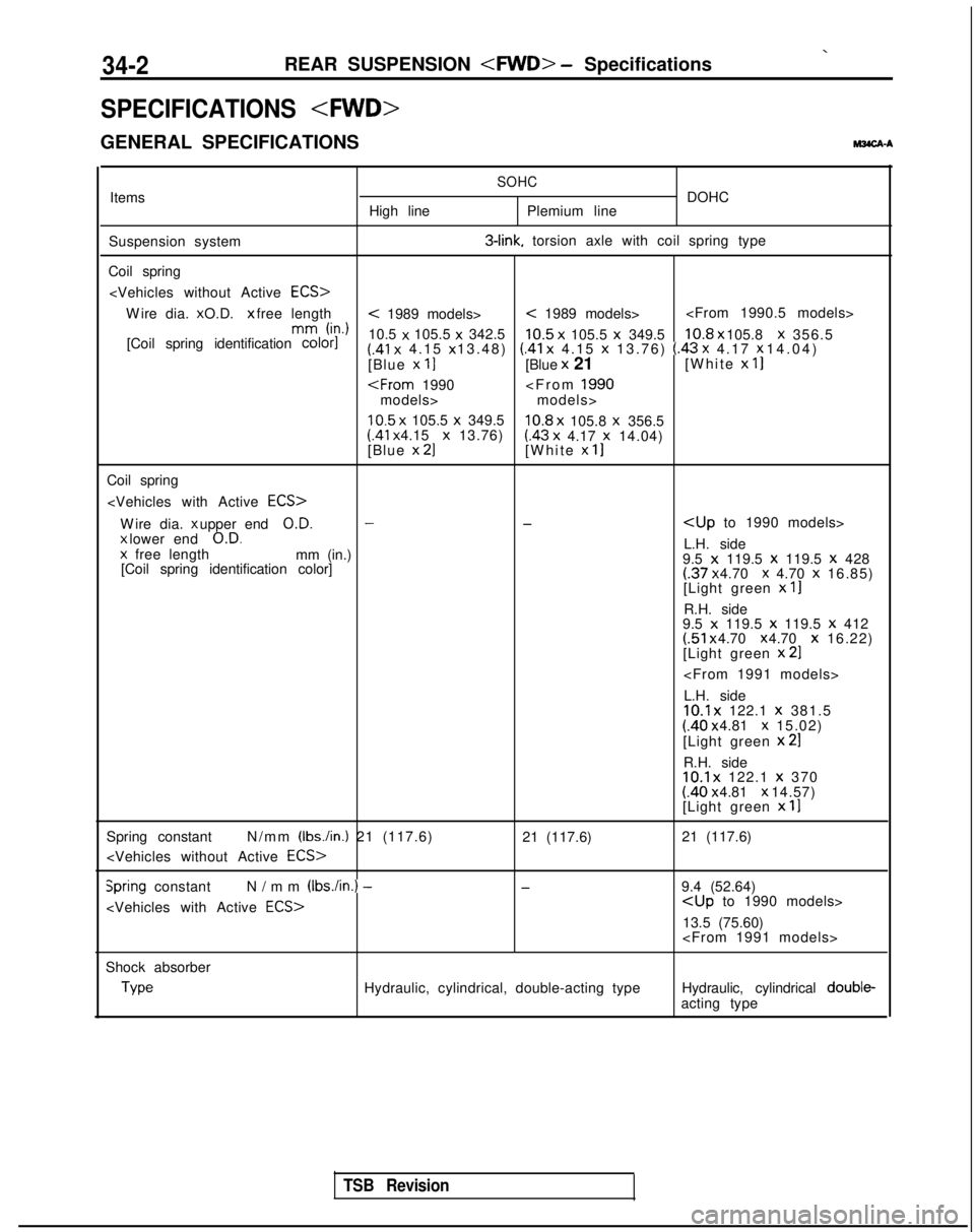
GENERAL SPECIFICATIONS
M3CA-A
Items
Suspension system
Coil spring High lineSOHCDOHC
Plemium line 3-link.
torsion axle with coil spring type
Wire dia. x O.D. x free length
< 1989 models>< 1989 models>
h-d
[Coil spring identification color]
10.5 x
105.5 x
342.5
10.5 x
105.5 x
349.510.8 x 105.8 x
356.5(.41 x
4.15 x 13.48) (.41 x
4.15 x
13.76) (.43 x 4.17 x 14.04)
[Blue x 11[Blue x
21 [White x
II
models>
10.5 x
105.5 x
349.510.8 x
105.8 x
356.5 (41
x 4.15 x
13.76)(.43 x
4.17 x
14.04)
[Blue x 21[White x 11
Coil spring
Wire dia. x upper end
O.D.--
x lower end
O.D.L.H. side
x
free length
mm (in.)
9.5 x 119.5 x
119.5 x
428
[Coil spring identification color](.37 x 4.70 x 4.70 x
16.85)
[Light green x
II
R.H. side
9.5 x 119.5 x
119.5 x 412(.51 x 4.70 x 4.70 x
16.22)
[Light green x
21
L.H. side
10.1 x
122.1 x
381.5(.40 x 4.81 x 15.02)
[Light green x
21
R.H. side10.1 x
122.1 x
370 (.40 x 4.81 x 14.57)
[Light green x
11
Spring constant N/mm (Ibs./in.) 21 (117.6)
21 (117.6)
21 (117.6)
Spring constant
N/mm (Ibs./in.) -
-9.4 (52.64)
13.5 (75.60)
Shock absorber Type
Hydraulic, cylindrical, double-acting type
Hydraulic, cylindrical double-
acting type
TSB Revision
Page 1084 of 1273
REAR SUSPENSION
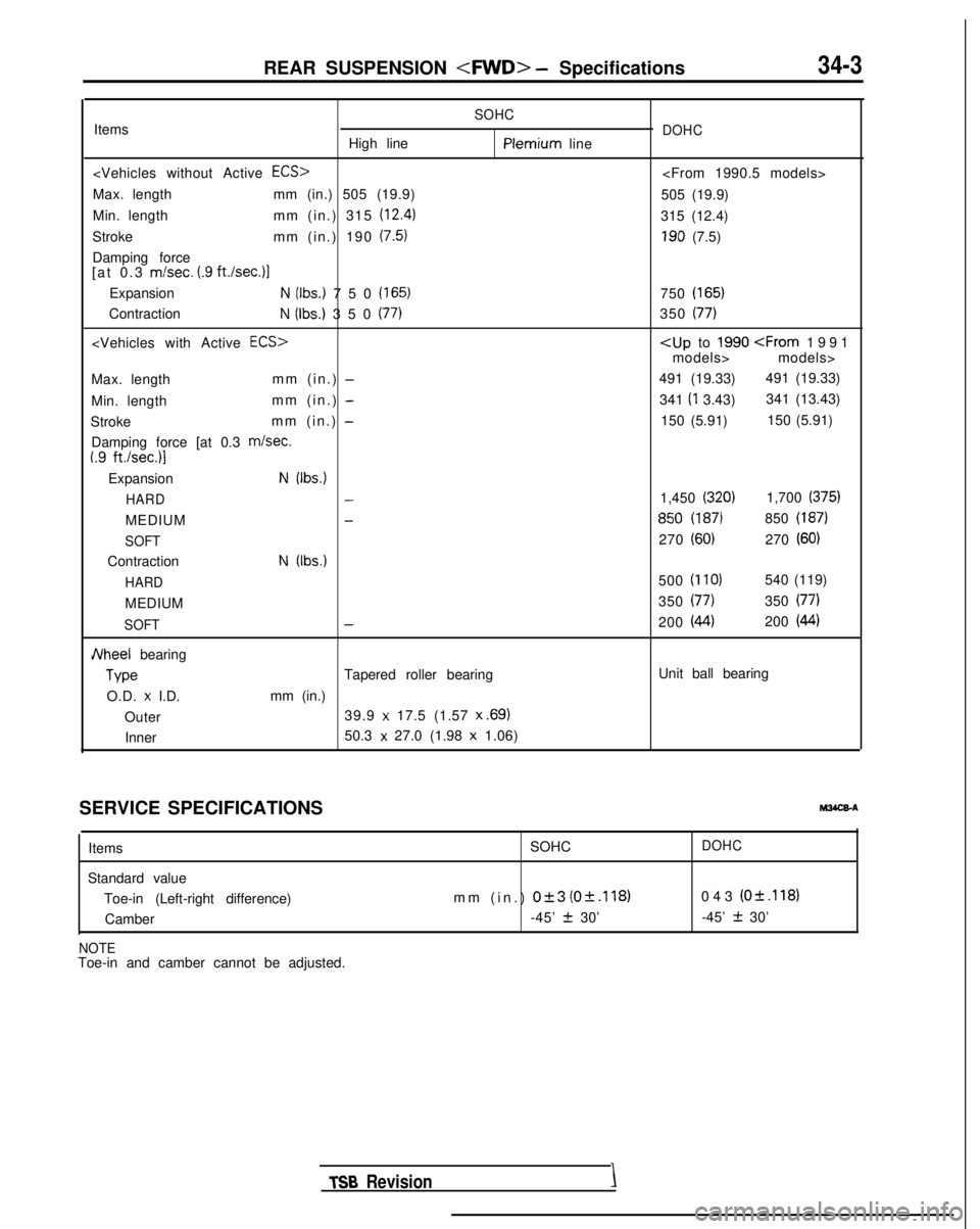
SOHCItems
High linePlemium line
Max. length mm (in.) 505 (19.9)
Min. length mm (in.) 315
(12.4)
Stroke mm (in.) 190 (7.5)
Damping force
[at 0.3 m/set. (.9 ft.Isec.11
ExpansionN (Ibs.) 750 (165)
ContractionN (Ibs.) 350 (77)
Max. length mm (in.) -
Min. lengthmm (in.) -
Stroke mm (in.) -
Damping force [at 0.3 m/set.I.9 ft./sec.)l
ExpansionN (Ibs.)
HARD
-
MEDIUM-
SOFT
ContractionN (Ibs.)
HARD
MEDIUM
SOFT-
JVheel bearing Type
Tapered roller bearing
O.D.
x I.D. mm (in.)
Outer 39.9
x 17.5 (1.57 x .69)
Inner
50.3 x 27.0 (1.98 x
1.06)
DOHC
505 (19.9)
315 (12.4)
190 (7.5)
750
(165)
350 (77)
models> models>
491 (19.33) 491 (19.33)
341 (I
3.43) 341 (13.43)
150 (5.91) 150 (5.91)
1,450
(320)1,700 (375)
850 (187)850 (187)
270 (60)270 (60)
500 (110)540 (119)
350
(77)350 (77)
200 (44)200 (44)
Unit ball bearing
SERVICE SPECIFICATIONS Items
Standard value Toe-in (Left-right difference)Camber
NOTEToe-in and camber cannot be adjusted.
MWX-A
SOHCDOHC
mm (in.) 0+3 (0+.118)043 (O&.118)
-45’
2 30’ -45’ + 30’ TSB
RevisionI
Page 1085 of 1273
34-4REAR SUSPENSION
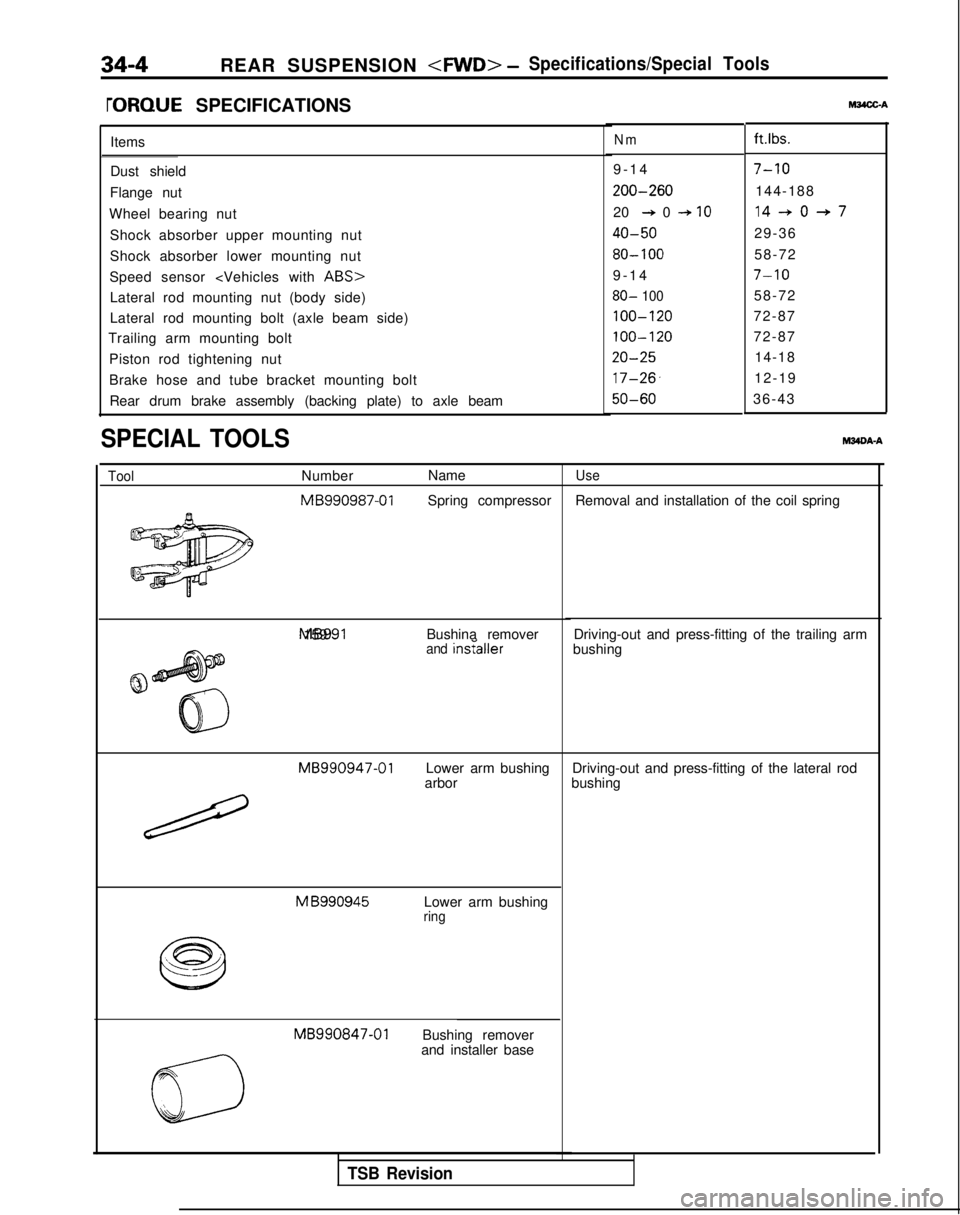
rORQUE SPECIFICATIONSt&4X-A
Items
Dust shield
Flange nut
Wheel bearing nut Shock absorber upper mounting nut
Shock absorber lower mounting nut
Speed sensor
Lateral rod mounting nut (body side)
Lateral rod mounting bolt (axle beam side)
Trailing arm mounting bolt
Piston rod tightening nut
Brake hose and tube bracket mounting boltRear drum brake assembly (backing plate) to axle beam
SPECIAL TOOLSM34DA-A
ToolNumber Name MB990987-01
Spring compressor MB991 159
Bushina remover
and insraIler
MB990947-01
Lower arm bushing
arbor M
B990945
Lower arm bushingring MB990847-01
Bushing remover
and installer base
Nmft.lbs.
9-1
4
7-10
200-260144-188
20
+ 0 + IO14-+0+7
40-5029-36
80- 10058-72
9-1
4
7-10
80- 10058-72
100-12072-87
100-12072-87
20-2514-18
17-26,12-19
50-6036-43
Use
Removal and installation of the coil spring
Driving-out and press-fitting of the trailing arm
bushing
Driving-out and press-fitting of the lateral rod
bushing
TSB Revision
Page 1086 of 1273
REAR SUSPENSION
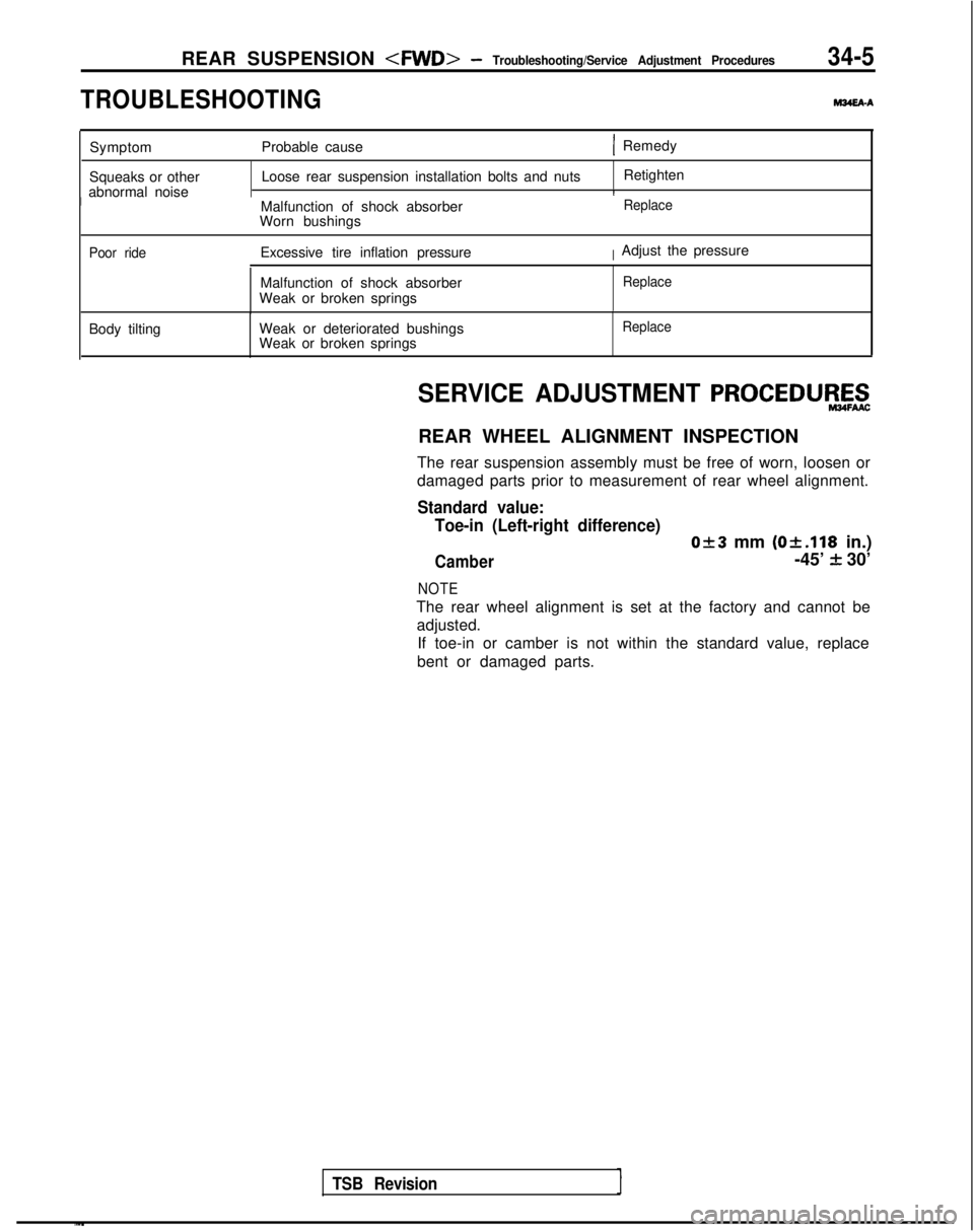
TROUBLESHOOTING
M34EAA
Symptom Probable cause( Remedy
Squeaks or other
abnormal noise Loose rear suspension installation bolts and nuts
Retighten
IMalfunction of shock absorber
Worn bushingsReplace
Poor ride
Excessive tire inflation pressureIAdjust the pressure
Malfunction of shock absorber
Weak or broken springs
Replace
Body tilting Weak or deteriorated bushings
Weak or broken springsReplace
TSB Revision
SERVICE ADJUSTMENT PROCEDUEZ$
REAR WHEEL ALIGNMENT INSPECTION
The rear suspension assembly must be free of worn, loosen or
damaged parts prior to measurement of rear wheel alignment.
Standard value: Toe-in (Left-right difference)
0+3 mm (Ok.118
in.)
Camber-45’ f 30’
NOTE
The rear wheel alignment is set at the factory and cannot be
adjusted. If toe-in or camber is not within the standard value, replace
bent or damaged parts.
Page 1087 of 1273
34-6REAR SUSPENSION
- Rear Suspension Assembly
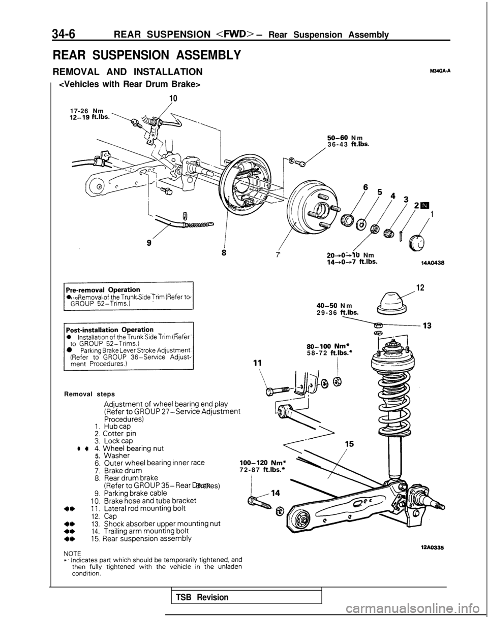
REAR SUSPENSION ASSEMBLY
REMOVAL AND INSTALLATION
10
17-26 Nm
12-19 “‘“s. y+.,
6 54 32w
dy4d
1
( t)e
._-.
l Removal of the Trunk Side Trim (Refer to
l installation of the Trunk Side Tnm (Referto GROUP 52-Trims.)l Parking Brake Lever Stroke Adjustment(Refer to GROUP
36-Service
Adjust-
Removal steps
Adjustment of wheel
bearing end play
(Refer
to GROUP 27-Service AdjustmentProcedures)1. Hubcap2.
Cotter
pin3. Lockcapl 44.
Wheel
bearing
nut5.
Washer
7:8.
9.10.11.
12.
13.
14.
M34GA.A
50-60 N
m
36-43 ft.lbs.
Outer
wheel bearing inner
raceBrake drumRear
drum
brake(Referto GROUP 35-Rear Drum Brakes)Parking brake
cableBrake
hose
and tube
bracket
Lateral rod mounting
bolt
CapShock
absorber
upper mounting
nut
Trailing
arm mounting
bolt7
20-*0~10Nm1440+7 ft.lbs.14AO438
12
40-50 N
m
29-36
ft.lbs.
80-100 Nm*58-72 ft.lbs.*
I
loo-120 Nm*72-87 ft.lbs.*
4*15. Rear suspension
assembly
12AO335NOTE
*. Indicates part which should be temporarily tightened, andthen
fully
tightened with the vehicle in the unladencondition.
TSB Revision
Page 1088 of 1273
REAR SUSPENSION
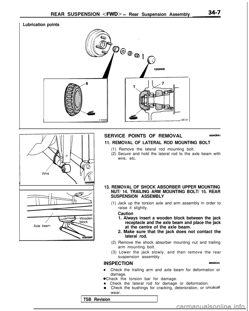
Lubrication points
12ElOl
SERVICE POINTS OF REMOVALM34GsAJ
11. REMOVAL OF LATERAL ROD MOUNTING BOLT
(1) Remove the lateral rod mounting bolt.
(2) Secure and hold the lateral rod to the axle beam with
wire, etc.
\
13. REMOVAL OF SHOCK ABSORBER UPPER MOUNTING-INUT/ 14. TRAILING ARM MOUNTING BOLT/ 15. REAR
SUSPENSION ASSEMBLY
(1) Jack up the torsion axle and arm assembly in order to
raise it slightly.
Caution1. Always insert a wooden block between the jack
receptacle and the axle beam and place the jack
at the centre of the axle beam.
2. Make sure that the jack does not contact the
lateral rod.
(2) Remove the shock absorber mounting nut and trailing arm mounting bolt.
(3) Lower the jack slowly, and then remove the rear suspension assembly.
INSPECTION
M34Glxl.
lCheck the trailing arm and axle beam for deformation or
damage. 0 Check the torsion bar for damage.
l Check the lateral rod for damage or deformation. 0
Check the bushings for cracking, deterioration, or
unusual
wear.
TSB Revision
Page 1089 of 1273
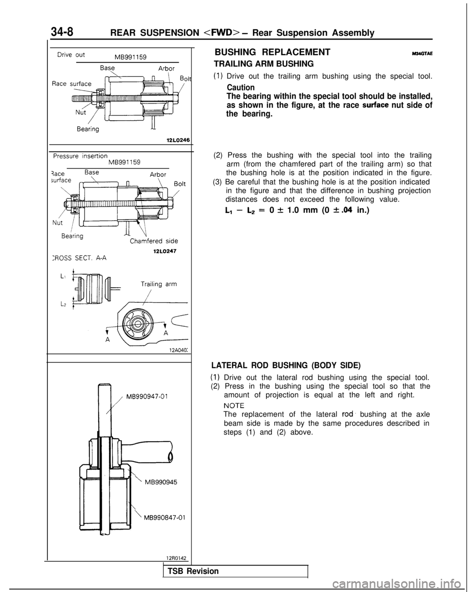
Drive out
Race
BUSHING REPLACEMENTM34GlAEMB991 159
BaseArborTRAILING ARM BUSHING
Oh(1) Drive out the trailing arm bushing using the special tool.
Caution
34-8REAR SUSPENSION
The bearing within the special tool should be installed,
as shown in the figure, at the race
surface nut side of
the bearing.
12LO246
Pressure insertionMB991159
XOSS SECT. A-A
Chamfered side
12LO247
12A040: k
MB990947-01
’ MB990945
\MB990847-01
12R0142(2) Press the bushing with the special tool into the trailing
arm (from the chamfered part of the trailing arm) so that
the bushing hole is at the position indicated in the figure.
(3) Be careful that the bushing hole is at the position indicated in the figure and that the difference in bushing projection
distances does not exceed the following value.
l-1 -L2 =0 f 1.0 mm (0 f .04 in.)
LATERAL ROD BUSHING (BODY SIDE)
(1) Drive out the lateral rod bushing using the special tool.
(2) Press in the bushing using the special tool so that the amount of projection is equal at the left and right. NOTE
The replacement of the lateral rod’
bushing at the axle
beam side is made by the same procedures described in
steps (1) and (2) above.
TSB Revision
Page 1090 of 1273
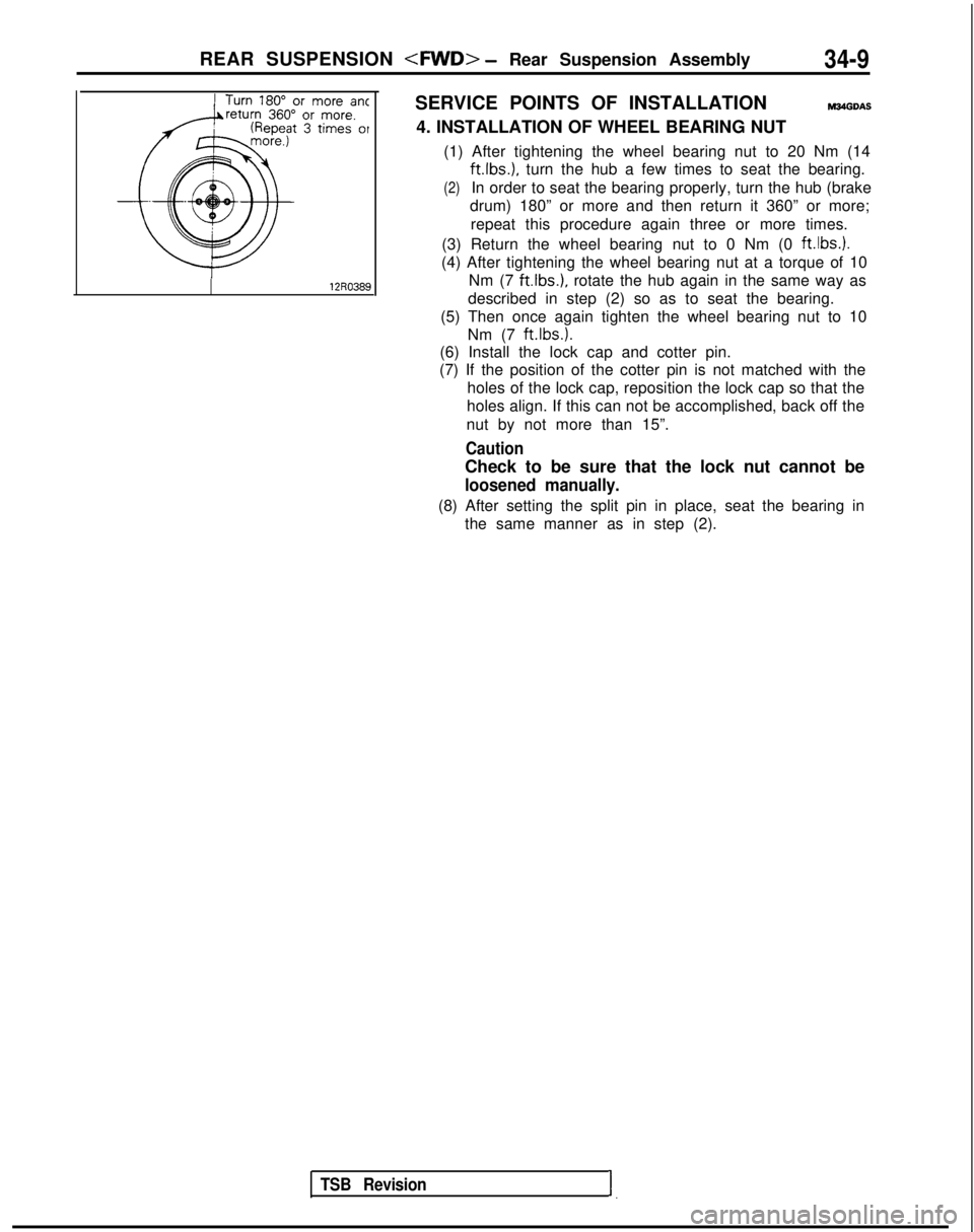
REAR SUSPENSION
Turn 180” or more antreturn360” or more.epeat 3
times of
TSB Revision1.
SERVICE POINTS OF INSTALLATIONMS4GDAS
4. INSTALLATION OF WHEEL BEARING NUT
(1) After tightening the wheel bearing nut to 20 Nm (14 ft.lbs.),
turn the hub a few times to seat the bearing.
(2)In order to seat the bearing properly, turn the hub (brake
drum) 180” or more and then return it 360” or more;
repeat this procedure again three or more times.
(3) Return the wheel bearing nut to 0 Nm (0 ft.lbs.).
(4) After tightening the wheel bearing nut at a torque of 10 Nm (7
ftlbs.), rotate the hub again in the same way as
described in step (2) so as to seat the bearing.
(5) Then once again tighten the wheel bearing nut to 10 Nm (7 ft.lbs.).
(6) Install the lock cap and cotter pin.
(7) If the position of the cotter pin is not matched with the
holes of the lock cap, reposition the lock cap so that the
holes align. If this can not be accomplished, back off the
nut by not more than 15”.
Caution
Check to be sure that the lock nut cannot be
loosened manually.
(8) After setting the split pin in place, seat the bearing in the same manner as in step (2).