MITSUBISHI GALANT 1989 Service Repair Manual
Manufacturer: MITSUBISHI, Model Year: 1989, Model line: GALANT, Model: MITSUBISHI GALANT 1989Pages: 1273, PDF Size: 37.62 MB
Page 1111 of 1273
34-30REAR SUSPENSION
PipeOuter pipe(lower (bushing)arm)
12AOO39
12A0100
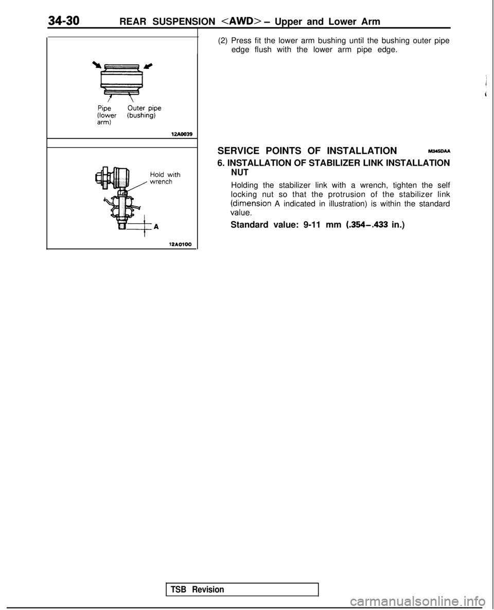
(2) Press fit the lower arm bushing until the bushing outer pipeedge flush with the lower arm pipe edge.
SERVICE POINTS OF INSTALLATION
M34sDAA
6. INSTALLATION OF STABILIZER LINK INSTALLATION
NUT
Holding the stabilizer link with a wrench, tighten the self
locking nut so that the protrusion of the stabilizer link
(cil;l,nsion A indicated in illustration) is within the standard
Standard value: 9-11 mm
(.364-433 in.)
TSB Revision
Page 1112 of 1273
REAR SUSPENSION
TRAILING ARM
REMOVAL AND INSTALLATION
160-220 Nm116-15y
ft.lbs.
9-14 Nm
7-10 ftlbs.
50-60 Nm
36-43 ft.lbs.
\
55-65 N
m
40-47 ft Ibs\ . .\~- -
140-160 Nm*101-116 ft.lbs.*
Connecting rod// I
Yli0
60-7i Nm
43-52 ft.lbs.
90-110 Nm65-80 ftlbs.
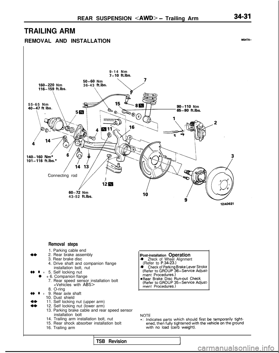
Removal steps
1. Parking cable end
4*2. Rear brake assembly
3. Rear brake disc
4. Drive shaft and companion flange
installation bolt, nut
4I) l +5. Self locking nut
l + 6. Companion flange 7. Rear speed sensor installation bolt
::11. Self locking nut (upper arm)
12. Self locking nut (lower arm)
13. Parking brake cable and rear speed sensor
installation bolt
14. Trailing arm installation bolt, nut
15. Rear shock absorber installation bolt
16. Trailing arm
12AO621
Post-installation Operationl Zheck of Wheel Alignment(Refer to P.3423.)l Check of Parking Brake Lever Stroke(Refer to GROUP 36-Service
Adjust-ment Procedures.)@Rear Brake Disc Run-out Check(Refer to GROUP 35Service Adjust-ment Procedures.)
NOTE*:Indicates parts which should
first
be temporarily tight-ened, then fully
tightened with
the vehicle on the ground with
no load (cerb weight).
TSB Revision I
Page 1113 of 1273
34-32REAR SUSPENSION
12AOO64
MB991 113-01
12AOO96-
SERVICE POINTS OF REMOVAL
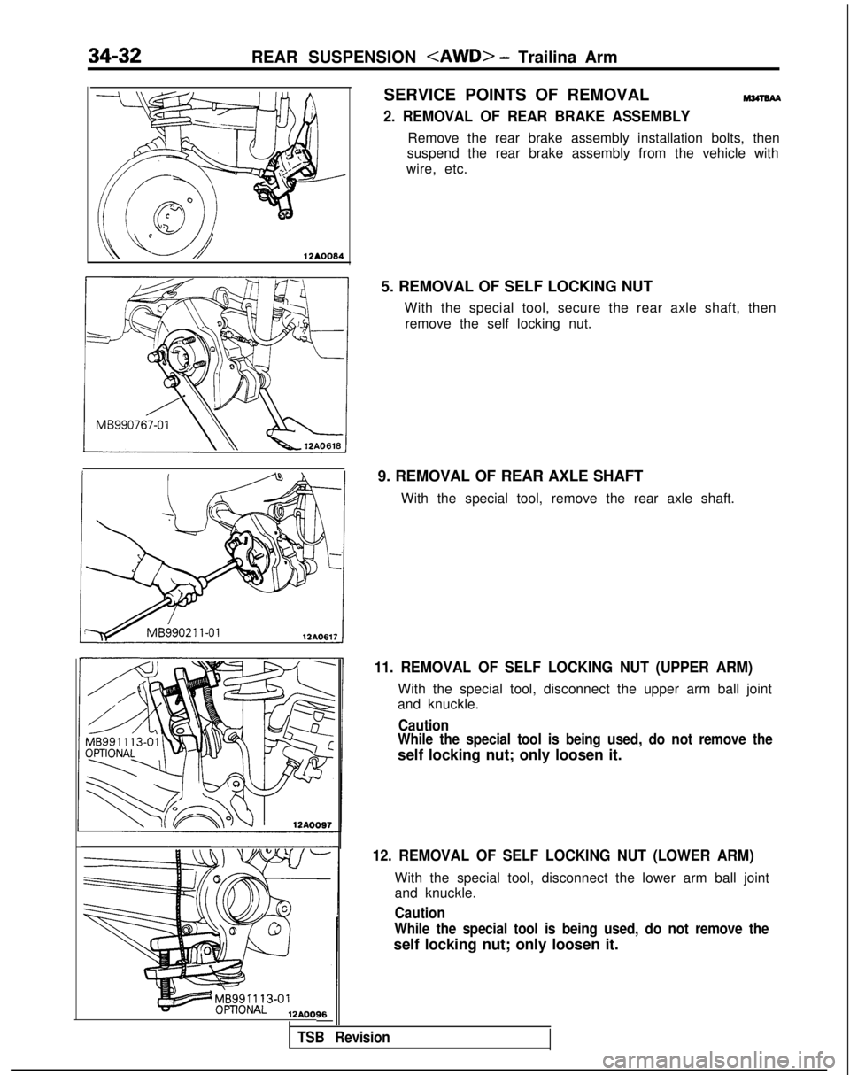
2. REMOVAL OF REAR BRAKE ASSEMBLY
Remove the rear brake assembly installation bolts, then
suspend the rear brake assembly from the vehicle with
wire, etc.
5. REMOVAL OF SELF LOCKING NUT With the special tool, secure the rear axle shaft, thenremove the self locking nut.
9. REMOVAL OF REAR AXLE SHAFT With the special tool, remove the rear axle shaft.
11. REMOVAL OF SELF LOCKING NUT (UPPER ARM)
With the special tool, disconnect the upper arm ball joint
and knuckle.
Caution
While the special tool is being used, do not remove the
self locking nut; only loosen it.
12. REMOVAL OF SELF LOCKING NUT (LOWER ARM)
With the special tool, disconnect the lower arm ball joint
and knuckle.
Caution
While the special tool is being used, do not remove the
self locking nut; only loosen it.
TSB Revision
Page 1114 of 1273
Pressure fittingRemoval
REAR SUSPENSION
M34TCAA
0 Check trailing arm for cracks and deformation.
l Check bushing for cracks, deterioration and wear.
TRAILING ARM BUSHING REPLACEMENT
wm
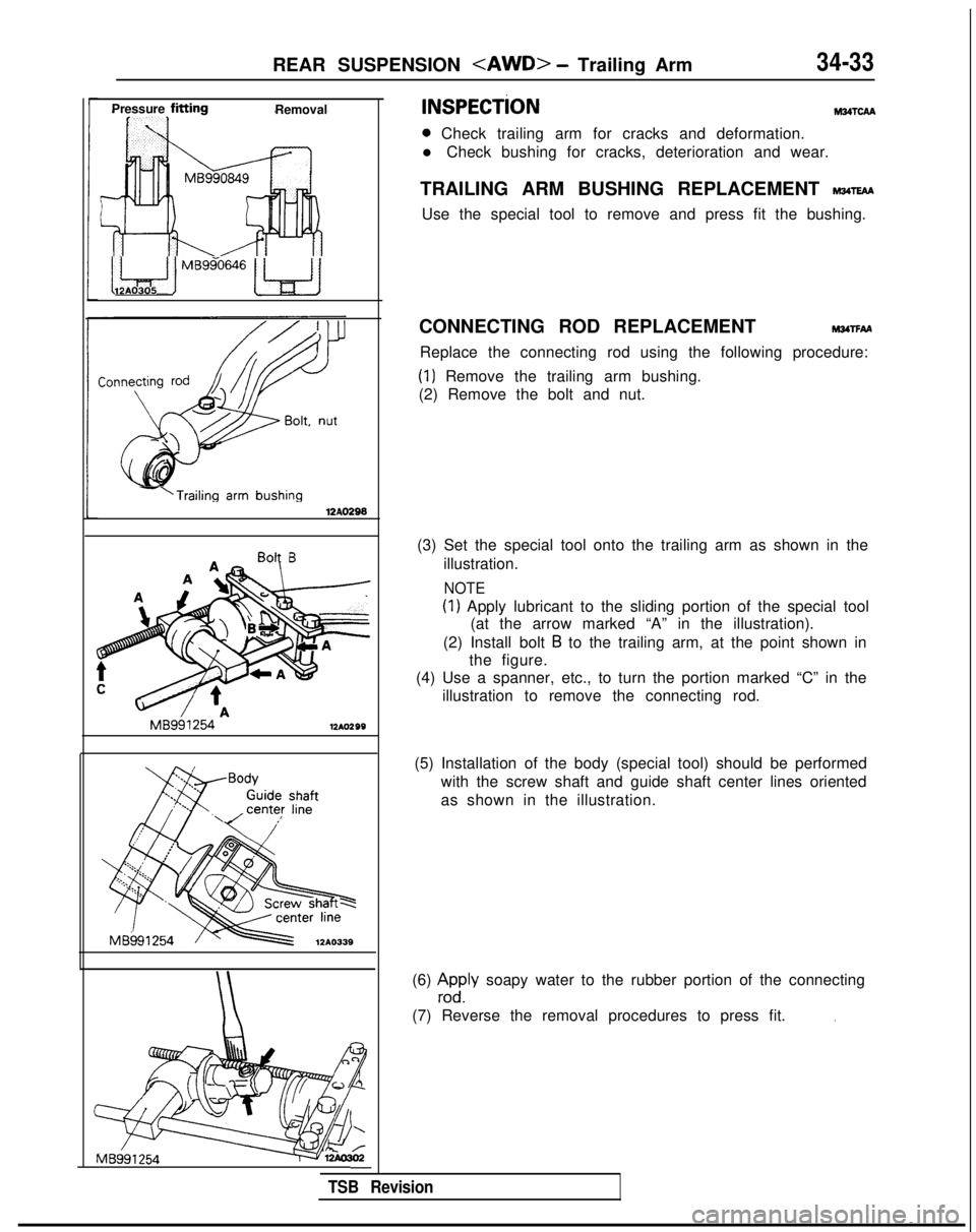
Use the special tool to remove and press fit the bushing.
i Le$ iMBggo646w12AO305
-‘Trailing arm
bushing12AO296
Bolt B
MB991254
12AO299
Body
Guide
shaftcenter line.\/ ’
MB991254
12A0339
MB991
254-
CONNECTING ROD REPLACEMENTMwrFAA
Replace the connecting rod using the following procedure:
(1) Remove the trailing arm bushing.
(2) Remove the bolt and nut.
(3) Set the special tool onto the trailing arm as shown in the illustration.
NOTE
(1) Apply lubricant to the sliding portion of the special tool(at the arrow marked “A” in the illustration).
(2) Install bolt
B to the trailing arm, at the point shown in
the figure.
(4) Use a spanner, etc., to turn the portion marked “C” in the
illustration to remove the connecting rod.
(5) Installation of the body (special tool) should be performed with the screw shaft and guide shaft center lines oriented
as shown in the illustration.
(6)
zdyly soapy water to the rubber portion of the connecting
(7) Reverse the removal procedures to press fit.
I
TSB Revision
Page 1115 of 1273
34-34REAR SUSPENSION
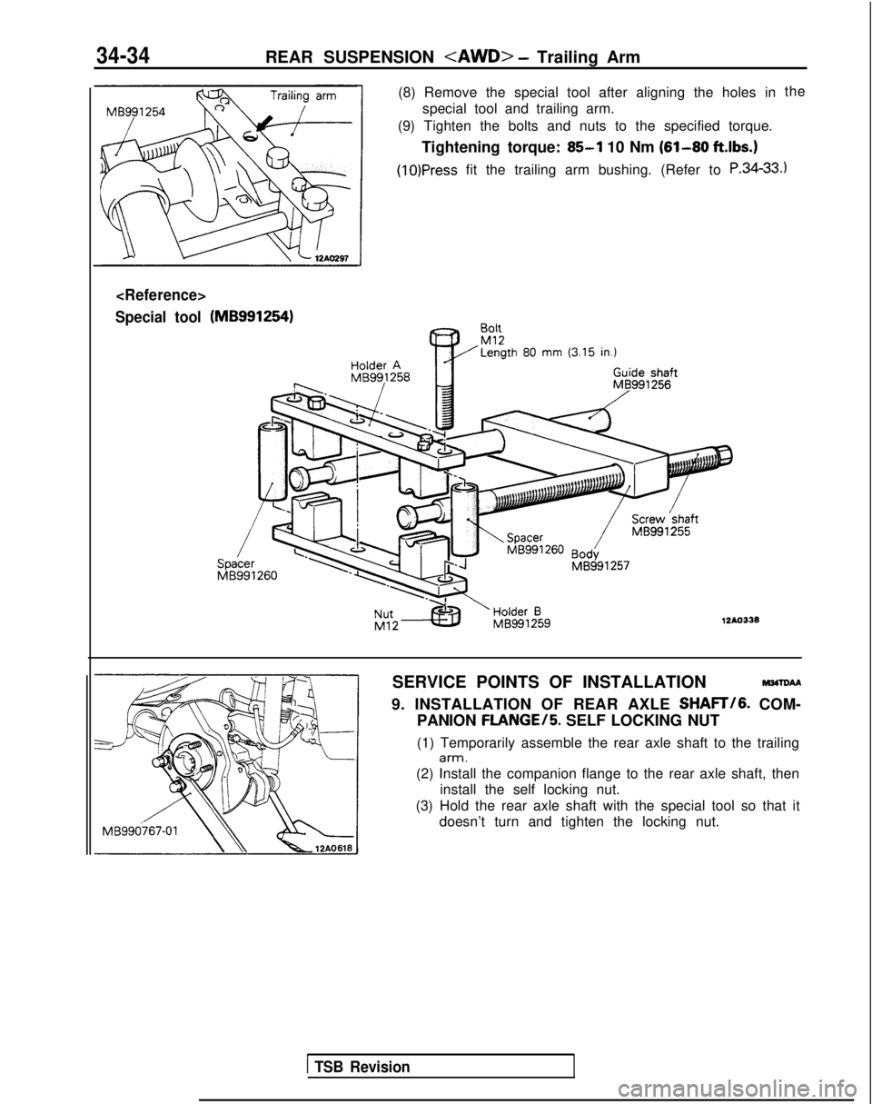
Special tool
(8) Remove the special tool after aligning the holes in special tool and trailing arm.
(9) Tighten the bolts and nuts to the specified torque.
Tightening torque:
85-l 10 Nm (61-80 ft.lbs.)
(10)Press fit the trailing arm bushing. (Refer to P.34-33
(MB991254)- Rnl1
Holder AMB991258
I”..Ml2 Length
80 mm
(3.15
in.) Guide
shaftMB991 256/
/
Screw
‘shaft MB991255
%’ Body
MB991 257
12AO336
the
.I
SERVICE POINTS OF INSTALLATIONM34ToAA
9. INSTALLATION OF REAR AXLE SHAFT/G. COM-
PANION
FLANGE/5. SELF LOCKING NUT
(1) Temporarily assemble the rear axle shaft to the trailing
arm.
(2) Install the companion flange to the rear axle shaft, then install the self locking nut.
(3) Hold the rear axle shaft with the special tool so that it doesn’t turn and tighten the locking nut.
1 TSB Revision
Page 1116 of 1273
REAR SUSPENSION
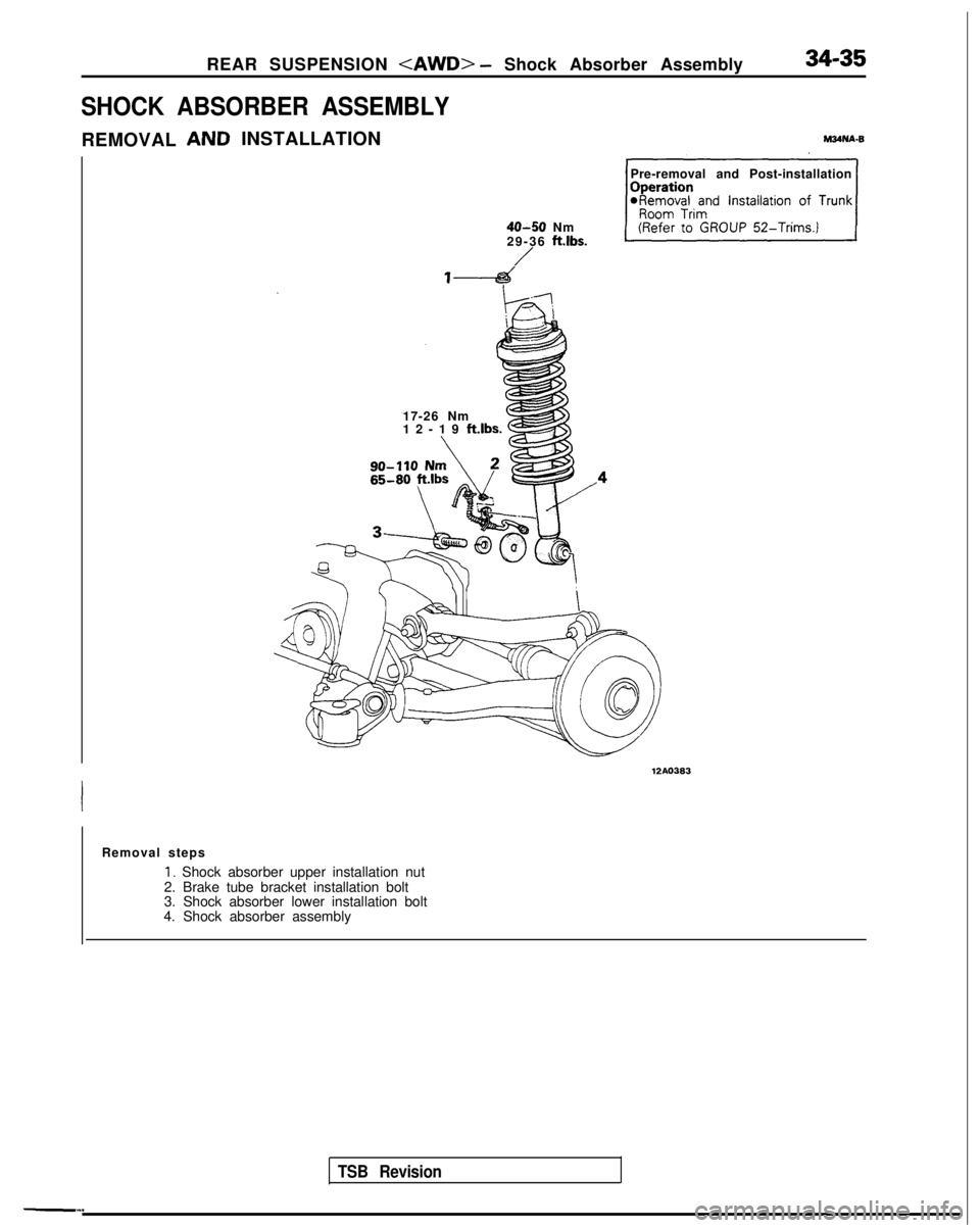
SHOCK ABSORBER ASSEMBLY
INSTALLATION
REMOVAL
17-26 Nm
12-19 ft.lbs.
6
Pre-removal and Post-installation
40-50 Nm
29-36 ftlbs.
/
TSB Revision
12AO383
Removal steps
I. Shock absorber upper installation nut
2. Brake tube bracket installation bolt
3. Shock absorber lower installation bolt
4. Shock absorber assembly
Page 1117 of 1273
34-36REAR SUSPENSION
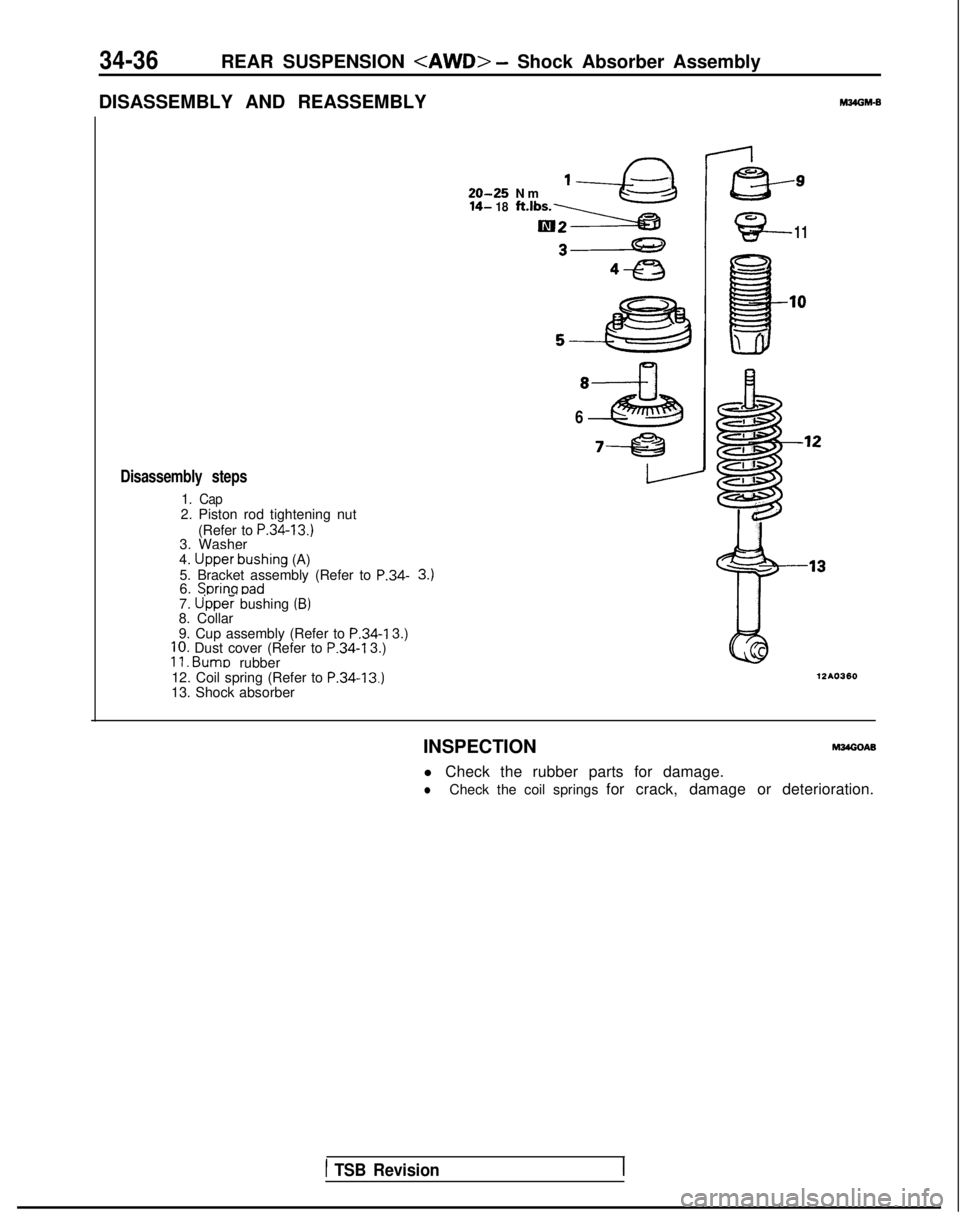
DISASSEMBLY AND REASSEMBLY
M34OM-B
Disassembly steps
1. Cap2. Piston rod tightening nut (Refer to
P.34-13.)3. Washer
4. Upper-bushing (A)
5. Bracket assembly (Refer to P.34-6. Sorina oad
20-25 N
m
14- 18
1-a
ft.‘bs-BS-
3J
e3
7. U’pper bushing (B)8. Collar
9. Cup assembly (Refer to
P.34-I
3.)
10. Dust cover (Refer to P.34-I
3.)11. Bums
rubber
12. Coil spring (Refer to P.34-13,)13. Shock absorber
INSPECTION
I-
B-9
G?-11
8
6
~-EB
12AO360
l Check the rubber parts for damage.
lCheck the coil springs for crack, damage or deterioration.
1 TSB Revision
Page 1118 of 1273
REAR SUSPENSION
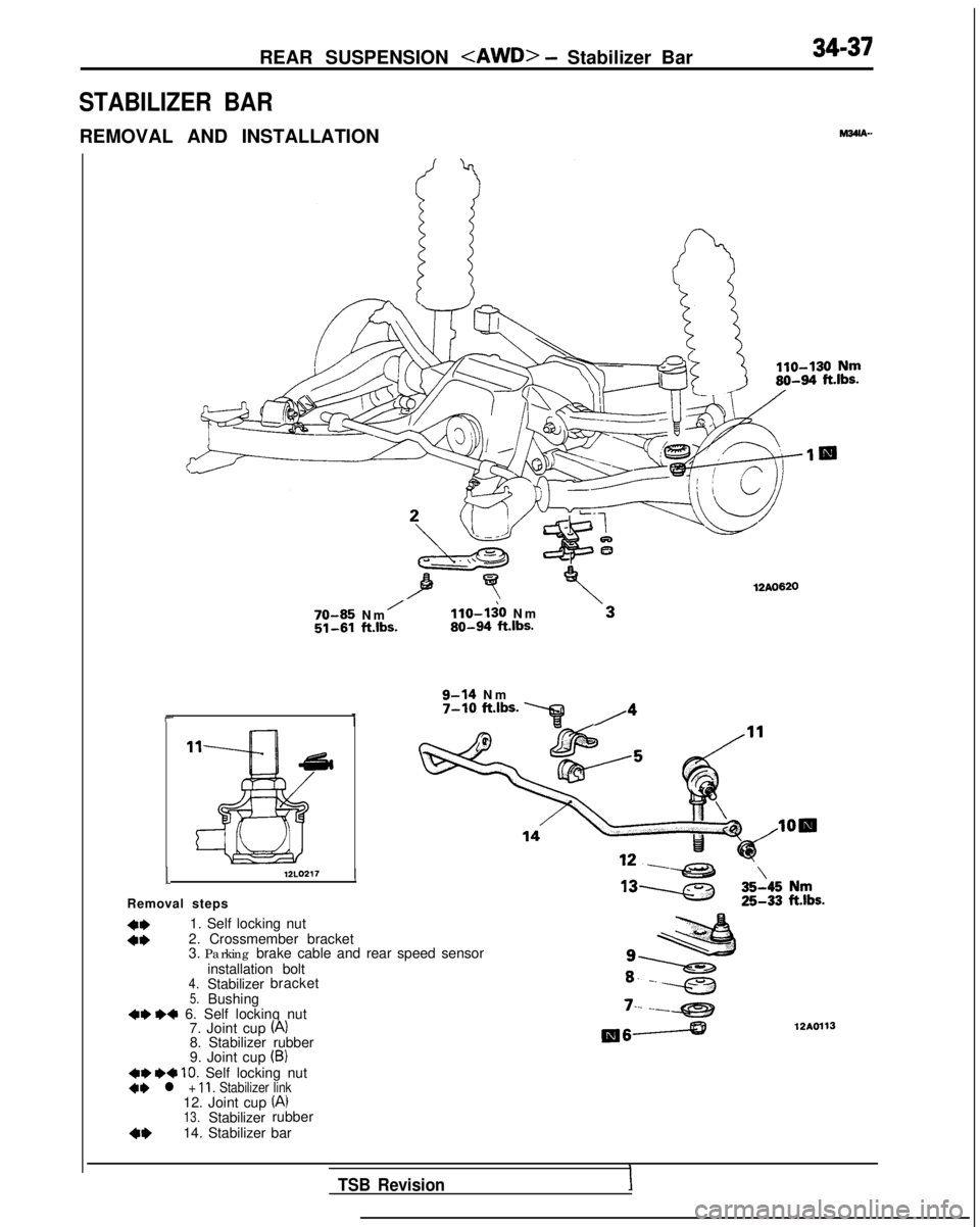
STABILIZER BAR
REMOVAL AND INSTALLATION
34-37
M36lA-
12AO620
70-85 N
m
/llo-li0 N
m
51-61 ft.lbs.80-94
ft.lbs.
9-14 N
m
7-10 ft.lbs. ‘q,4I-
112L0217
Removal steps
*I)1. Self locking nut
4*2. Crossmember bracket
3. Parking brake cable and rear speed sensor
installation bolt
4.Stabilizer bracket5.Bushing+e I)+ 6. Self locking nut
7. Joint cup (A)8. Stabilizer rubber
9. Joint cup (B)+e e+ 10. Self locking nut+e l + 11. Stabilizer link12. Joint cup (A)
13.Stabilizer rubber
4w14. Stabilizer bar
7-- --e
IllSA12A0113
TSB Revision
Page 1119 of 1273
34-38
REAR SUSPENSION
II12AO109
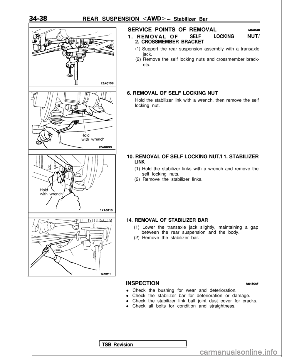
/ 12AOllOSERVICE POINTS OF REMOVAL
M34lDAB
1. REMOVAL O
F
SELFLOCKINGNUT/
2. CROSSMEMBER BRACKET
(1) Support the rear suspension assembly with a transaxle
jack.
(2) Remove the self locking nuts and crossmember brack-
ets.
6. REMOVAL OF SELF LOCKING NUT Hold the stabilizer link with a wrench, then remove the self
locking nut.
10. REMOVAL OF SELF LOCKING NUT/l 1. STABILIZER
LINK
(1) Hold the stabilizer links with a wrench and remove the self locking nuts.
(2) Remove the stabilizer links.
14. REMOVAL OF STABILIZER BAR
(1) Lower the transaxle jack slightly, maintaining a gap between the rear suspension and the body.
(2) Remove the stabilizer bar.
INSPECTION
M34TcAF
l Check the bushing for wear and deterioration.
l Check the stabilizer bar for deterioration or damage.
l Check the stabilizer link ball joint dust cover for cracks.
l Check all bolts for condition and straightness.
1 TSB Revision
Page 1120 of 1273
REAR SUSPENSION
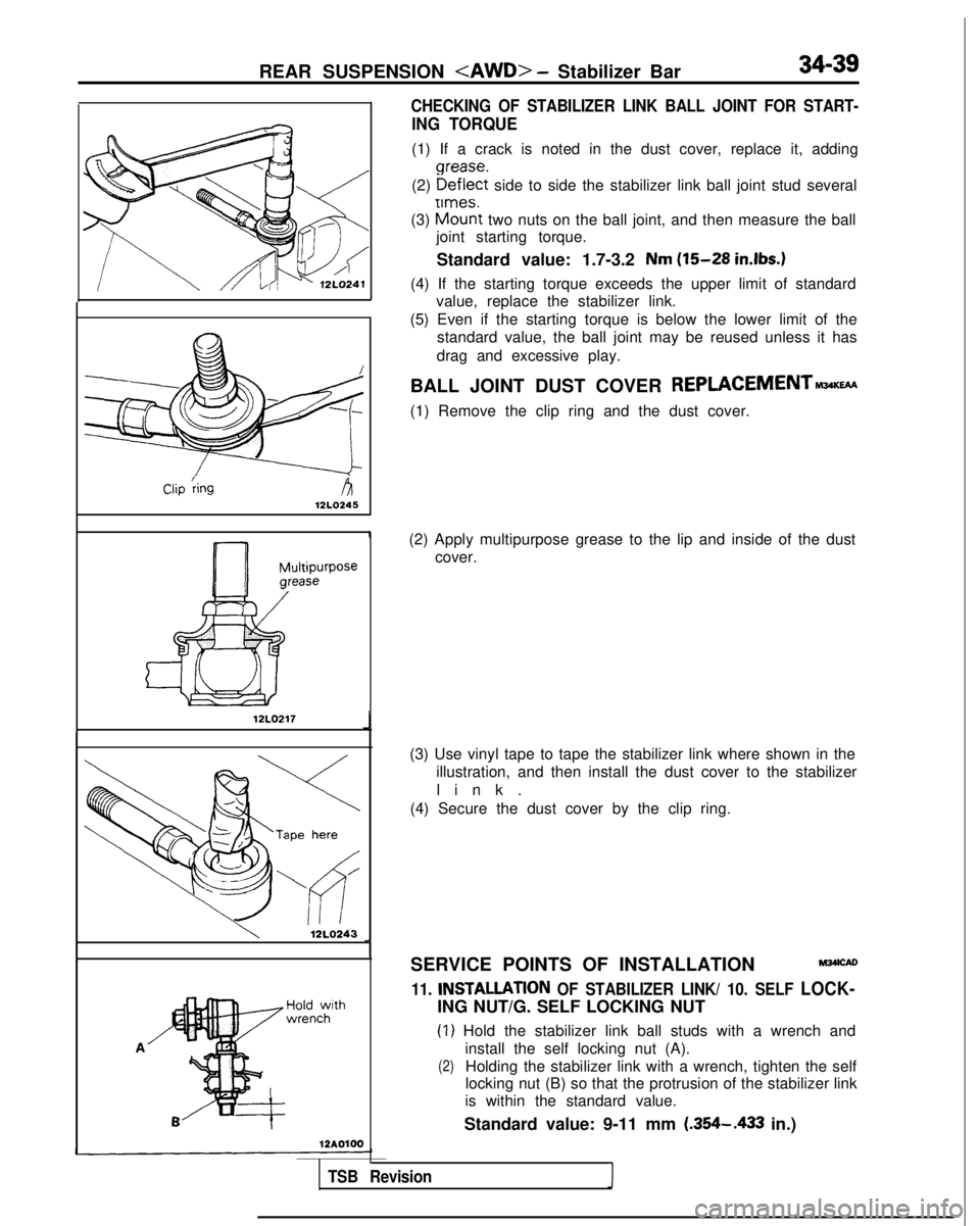
CHECKING OF STABILIZER LINK BALL JOINT FOR START-
ING TORQUE
(1) If a crack is noted in the dust cover, replace it, adding
(2)
gz;zEt side to side the stabilizer link ball joint stud several
(3)
h!z% two nuts on the ball joint, and then measure the ball
joint starting torque.
Standard value: 1.7-3.2
Nm (15-28 in.lbs.1
(4) If the starting torque exceeds the upper limit of standard value, replace the stabilizer link.
(5) Even if the starting torque is below the lower limit of the standard value, the ball joint may be reused unless it has
drag and excessive play. Clip
kgA12LO245
I
12LO217J
12LO243J
Hold
withwrench 12AOlOOBALL JOINT DUST COVER
REPLACEMENT-w
(1) Remove the clip ring and the dust cover.
(2) Apply multipurpose grease to the lip and inside of the dust cover.
(3) Use vinyl tape to tape the stabilizer link where shown in the illustration, and then install the dust cover to the stabilizer
link
.
(4) Secure the dust cover by the clip ring.
SERVICE POINTS OF INSTALLATION
11. INSTALLATlON OF STABILIZER LINK/ 10. SELF LOCK-
ING NUT/G. SELF LOCKING NUT
(1) Hold the stabilizer link ball studs with a wrench and install the self locking nut (A).
(2)Holding the stabilizer link with a wrench, tighten the self
locking nut (B) so that the protrusion of the stabilizer link
is within the standard value.
Standard value: 9-11 mm (.354-.433
in.)
TSB Revision1