MITSUBISHI GALANT 1989 Service Repair Manual
Manufacturer: MITSUBISHI, Model Year: 1989, Model line: GALANT, Model: MITSUBISHI GALANT 1989Pages: 1273, PDF Size: 37.62 MB
Page 1071 of 1273
33B-132 ACTIVE-ELECTRONIC CONTROL SUSPENSION - p$? Va’ve and
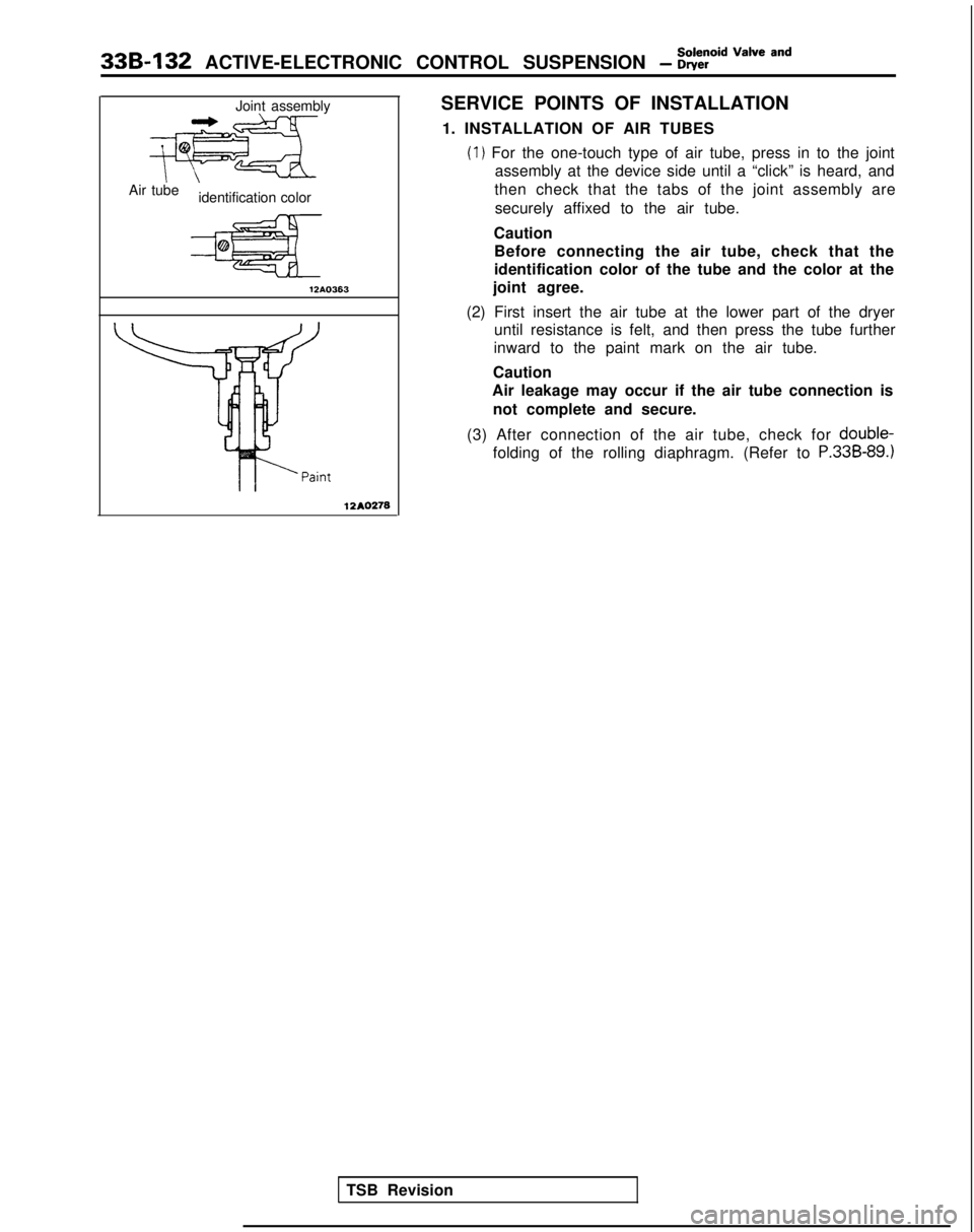
Joint assembly
ezAir tubeidentification color
12AO363
12AO278
SERVICE POINTS OF INSTALLATION
1. INSTALLATION OF AIR TUBES
(1) For the one-touch type of air tube, press in to the joint assembly at the device side until a “click” is heard, and
then check that the tabs of the joint assembly are
securely affixed to the air tube.
Caution Before connecting the air tube, check that the
identification color of the tube and the color at the
joint agree.
(2) First insert the air tube at the lower part of the dryer until resistance is felt, and then press the tube further
inward to the paint mark on the air tube.
Caution
Air leakage may occur if the air tube connection is
not complete and secure.
(3) After connection of the air tube, check for double-
folding of the rolling diaphragm. (Refer to P.338-89.)
TSB Revision
Page 1072 of 1273
ACTIVE-ELECTRONIC CONTROL SUSPENSION - Air tube336-133
AIR TUBEM332QAC
REMOVAL AND INSTALLATION
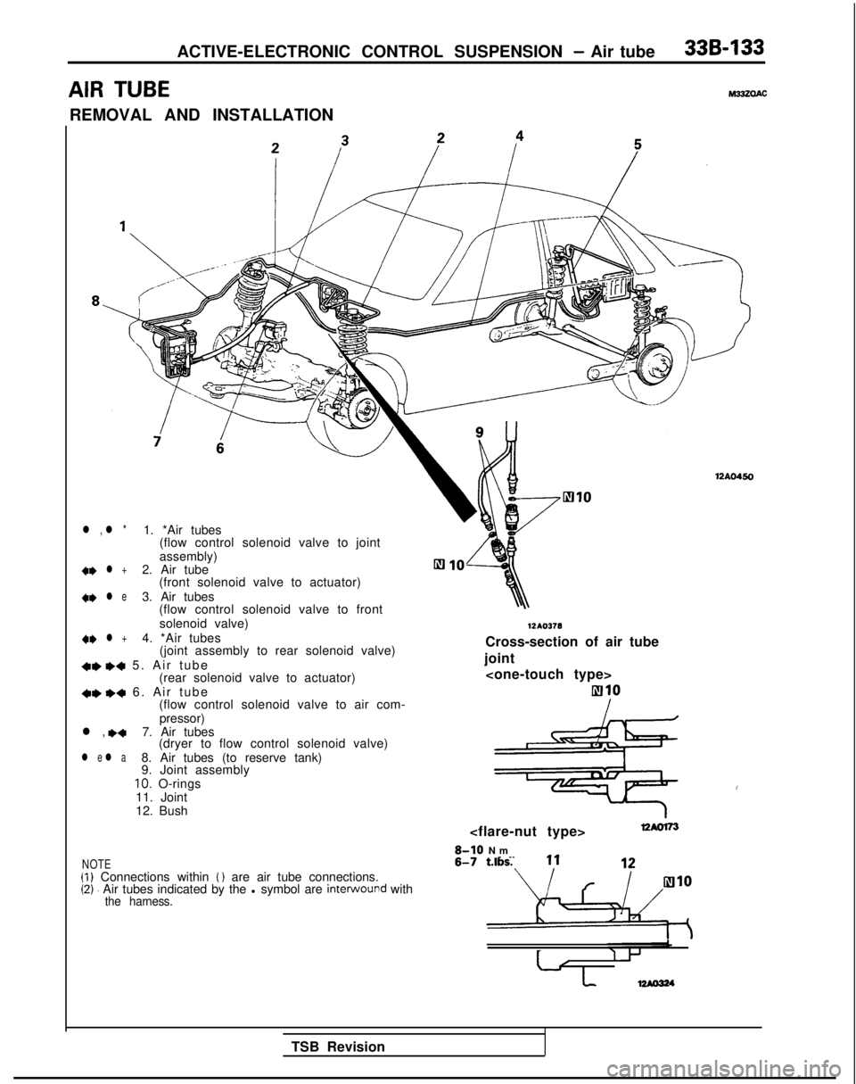
l , l *1. *Air tubes
(flow control solenoid valve to joint
assembly) +e
l +2. Air tube
(front solenoid valve to actuator) +e
l e3. Air tubes
(flow control solenoid valve to front
solenoid valve)
4~ l +4. *Air tubes (joint assembly to rear solenoid valve)
+, I)+ 5. Air tub
e
(rear solenoid valve to actuator)
+e ++ 6. Air tub
e
(flow control solenoid valve to air com-
pressor)
l , ,+7. Air tubes (dryer to flow control solenoid valve)
l e l a8. Air tubes (to reserve tank)
9. Joint assembly
10. O-rings
11. Joint
12. Bush
NOTE(1) Connections within ( ) are air tube connections.(2). Air tubes indicated by the l symbol are interwound withthe harness.
12AO450 12AO378
Cross-section of air tube
joint
810
I
S-IO N
m
8-7 ftlbs. 11
I
TSB Revision
Page 1073 of 1273
33B-134ACTIVE-ELECTRONIC CONTROL SUSPENSION - Air tube
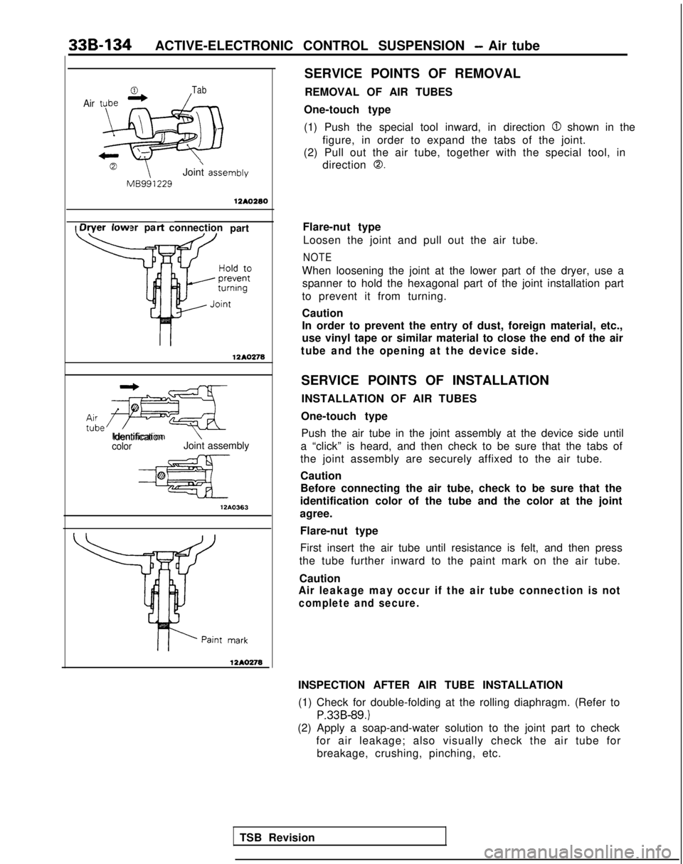
Air
Tab
\Joint asset
MB991229nbly
12AO280
Dryer lower pa
\
t-t connection
part Flare-nut type
Loosen the joint and pull out the air tube.
NOTE
12A0278
When loosening the joint at the lower part of the dryer, use aspanner to hold the hexagonal part of the joint installation part
to prevent it from turning.
Caution
In order to prevent the entry of dust, foreign material, etc.,
use vinyl tape or similar material to close the end of the air
tube and the opening at the device side.
tLe*~Identification
colorJoint assembly 12AO363
1210278
SERVICE POINTS OF REMOVAL
REMOVAL OF AIR TUBES
One-touch type
(1) Push the special tool inward, in direction
0 shown in the
figure, in order to expand the tabs of the joint.
(2) Pull out the air tube, together with the special tool, in direction
0.
SERVICE POINTS OF INSTALLATION
INSTALLATION OF AIR TUBES
One-touch type Push the air tube in the joint assembly at the device side until
a “click” is heard, and then check to be sure that the tabs of
the joint assembly are securely affixed to the air tube.
Caution
Before connecting the air tube, check to be sure that the
identification color of the tube and the color at the joint
agree.
Flare-nut type
First insert the air tube until resistance is felt, and then press
the tube further inward to the paint mark on the air tube.
Caution
Air leakage may occur if the air tube connection is not
complete and secure.
INSPECTION AFTER AIR TUBE INSTALLATION
(1) Check for double-folding at the rolling diaphragm. (Refer to
P.33B-89.)
(2) Apply a soap-and-water solution to the joint part to check for air leakage; also visually check the air tube forbreakage, crushing, pinching, etc.
TSB Revision
Page 1074 of 1273
ACTIVE-ELECTRONIC CONTROL SUSPENSION - Heiaht Sensor 33B-135
HEIGHT SENSOR
REMOVAL AND INSTALLATION
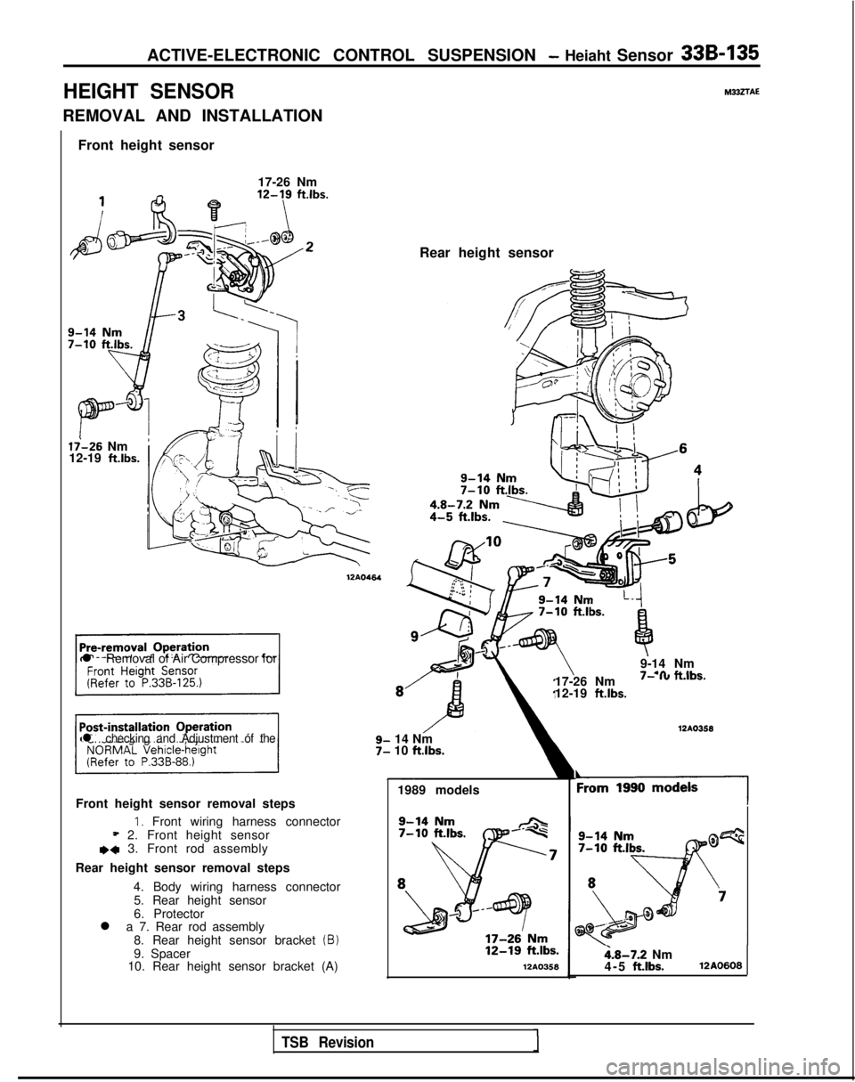
Front height sensor
17-26 Nm
li-26 Nm
12-19 ft.lbs.
l Removal of Air Compressor for
17-26 Nm
I- I” n.,os.
12-19 ft.lbs.
l checking and Adjustment of the14 Nm
10 ftlbs.
1989 models
Front height sensor removal steps
1. Front wiring harness connector* 2. Front height sensore+ 3. Front rod assembly
Rear height sensor removal steps 4. Body wiring harness connector5. Rear height sensor
6. Protector
l a 7. Rear rod assembly
8. Rear height sensor bracket
(B)9. Spacer
10. Rear height sensor bracket (A)l2A0358 12AO464
M332TAE
Rear height sensor
9-14 Nm
- .a #.&IL- 12AO358
‘19901
i.8-7.2 Nm
4-5 ft.lbs.12A0608
TSB Revision
Page 1075 of 1273
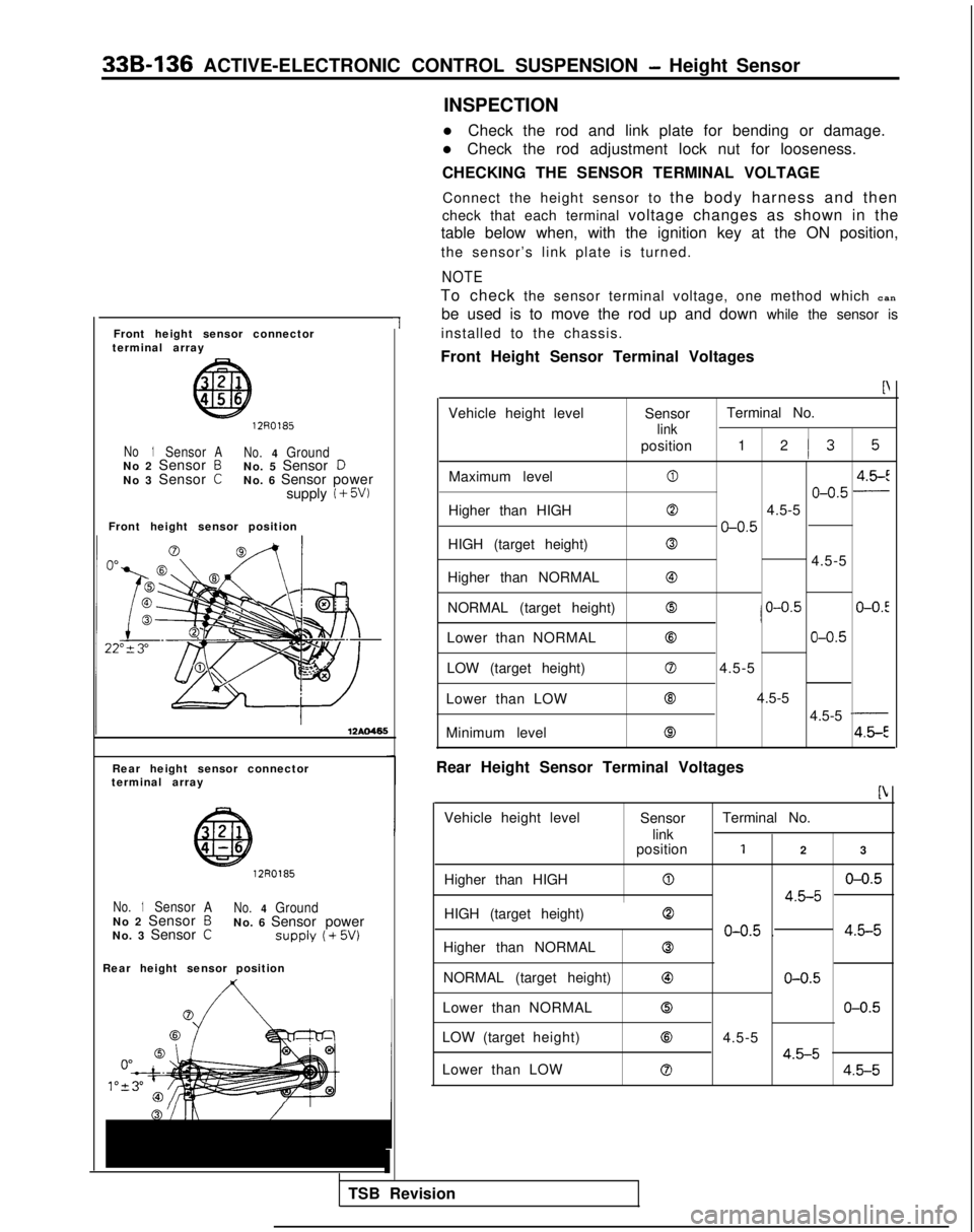
33B-136 ACTIVE-ELECTRONIC CONTROL SUSPENSION - Height Sensor
Front height sensor connector
terminal array
1
1270185
No1SensorA No.4GroundNo 2 Sensor BNo. 5 Sensor DNo 3 Sensor CNo. 6 Sensor power
supply i + 5W
Front height sensor position
Rear height sensor connector
terminal array
12R0185
No.1Sensor ANo.4GroundNo 2 Sensor BNo. 6 Sensor power
No. 3 Sensor CSUPPlY (+ 5w
Rear height sensor position
1
TSB Revision INSPECTION
l Check the rod and link plate for bending or damage.
l Check the rod adjustment lock nut for looseness.
CHECKING THE SENSOR TERMINAL VOLTAGE
Connect the height sensor to the body harness and then
check that each terminal voltage changes as shown in the
table below when, with the ignition key at the ON position,
the sensor’s link plate is turned.
NOTE
To check the sensor terminal voltage, one method which can
be used is to move the rod up and down while the sensor is
installed to the chassis.
Front Height Sensor Terminal Voltages
P
Vehicle height level SensorTerminal No.
link
position
1 2I3 5
Maximum level04.5-E
o-o.5 -
Higher than HIGH04.5-5
o-o.5
HIGH (target height)0
4.5-5
Higher than NORMAL
@
NORMAL (target height)0/ o-o.5O-O.!
Lower than NORMAL63o-o.5
LOW (target height)04.5-5
Lower than LOW Q 4.5-5
4.5-5
-
Minimum level84.5-E
Rear Height Sensor Terminal Voltages
b
Vehicle height level SensorTerminal No.
link
position
12 3
Higher than HIGH
0o-o.5
4.5-5
HIGH (target height)0
o-o.5 .4.5-5
Higher than NORMAL0
NORMAL (target height)63o-o.5
Lower than NORMAL0o-o.5
LOW (target height)84.5-5
4.5-5Lower than LOW04.5-5
Page 1076 of 1273
ACTIVE-ELECTRONIC CONTROL SUSPENSION - Height Sensor 33B-137
From1990 models
GoodIBad1
II
12R0363
Bolt centerleft edgesurface
SERVICE POINTS OF INSTALLATION
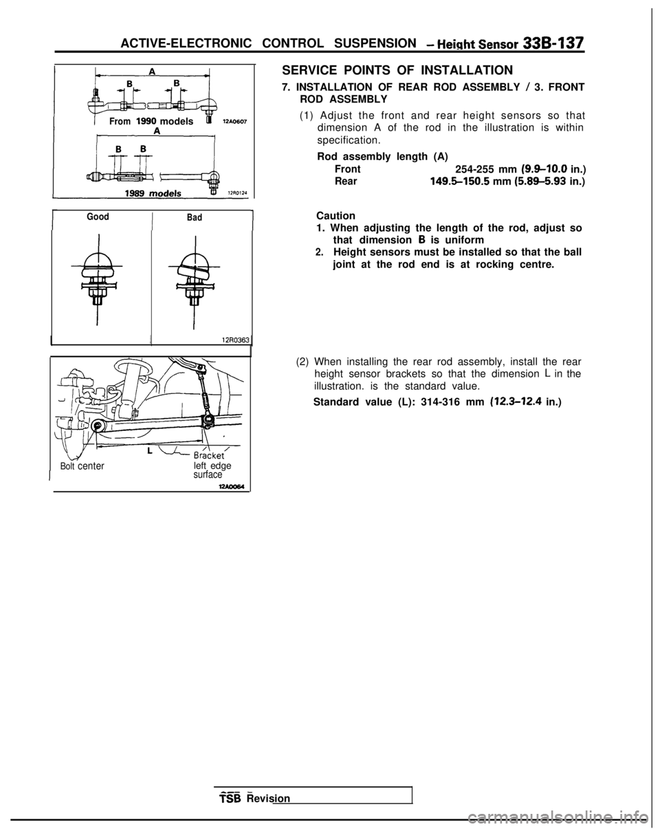
7. INSTALLATION OF REAR ROD ASSEMBLY
/ 3. FRONT
ROD ASSEMBLY
(1) Adjust the front and rear height sensors so that dimension A of the rod in the illustration is within
specification.
Rod assembly length (A)
Front254-255 mm (9.9-10.0 in.)
Rear 149.5-150.5
mm (5.89-5.93
in.)
Caution
1. When adjusting the length of the rod, adjust so that dimension
B is uniform
2.Height sensors must be installed so that the ball
joint at the rod end is at rocking centre.
(2) When installing the rear rod assembly, install the rear height sensor brackets so that the dimension
L in the
illustration. is the standard value.
Standard value (L): 314-316 mm
(12.3-12.4 in.)
a-- - TSB
Revision
Page 1077 of 1273
33B-138 ACTIVE-ELECTRONIC CONTROL SUSPENSION - ACTIVE-ECS Sensor
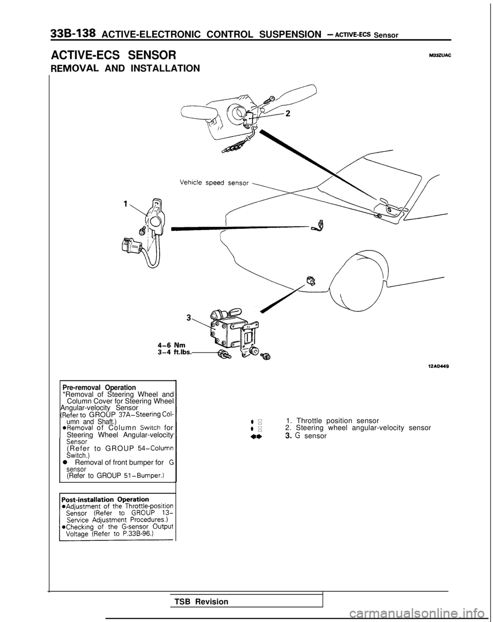
ACTIVE-ECS SENSORM33ZVAC
IEMOVAL
AND INSTALLATION
Pre-removal Operation*Removal of Steering Wheel and
Column Cover for Steering Wheel
Angular-velocity Sensor
(Referto GROUP 37A-Steering Cof-umn and Shaft.) ~
@Removal of Column Switch for
Steering Wheel Angular-velocity
Sensor-(Refer to GROUP 54-ColumnSwitch.)l Removal of front bumper forGsensor(Refer to GROUP 51-Bumper.)
1210449
l *1. Throttle position sensor
l *2. Steering wheel angular-velocity sensor
4*3. G sensor
TSB Revision
Page 1078 of 1273
ACTIVE-ELECTRONIC CONTROL SUSPENSION - ACTIVE-
ECS Sensor 33B-139
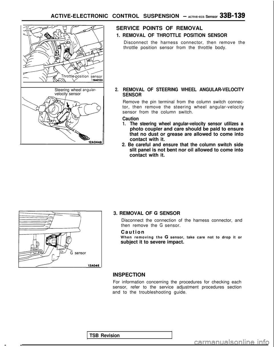
Steering wheel angular-velocity sensor
TSB Revision--
12A046
SERVICE POINTS OF REMOVAL
1. REMOVAL OF THROTTLE POSITION SENSOR
Disconnect the harness connector, then remove the
throttle position sensor from the throttle body.
2.REMOVAL OF STEERING WHEEL ANGULAR-VELOCITY
SENSOR
Remove the pin terminal from the column switch connec-
tor, then remove the steering wheel angular-velocity sensor from the column switch.
Caution
1.The steering wheel angular-velocity sensor utilizes a
photo coupler and care should be paid to ensure
that no dust or grease are allowed to come into contact with it.
2. Be careful and ensure that the column switch side
slit panel is not bent nor oil allowed to come into
contact with it.
3. REMOVAL OF
G SENSOR
Disconnect the connection of the harness connector, and
then remove the
G sensor.
Cautio
n
When removing the
G sensor, take care not to drop it or
subject it to severe impact.
INSPECTION For information concerning the procedures for checking each
sensor, refer to the service adjustment procedures section
and to the troubleshooting guide.
Page 1079 of 1273
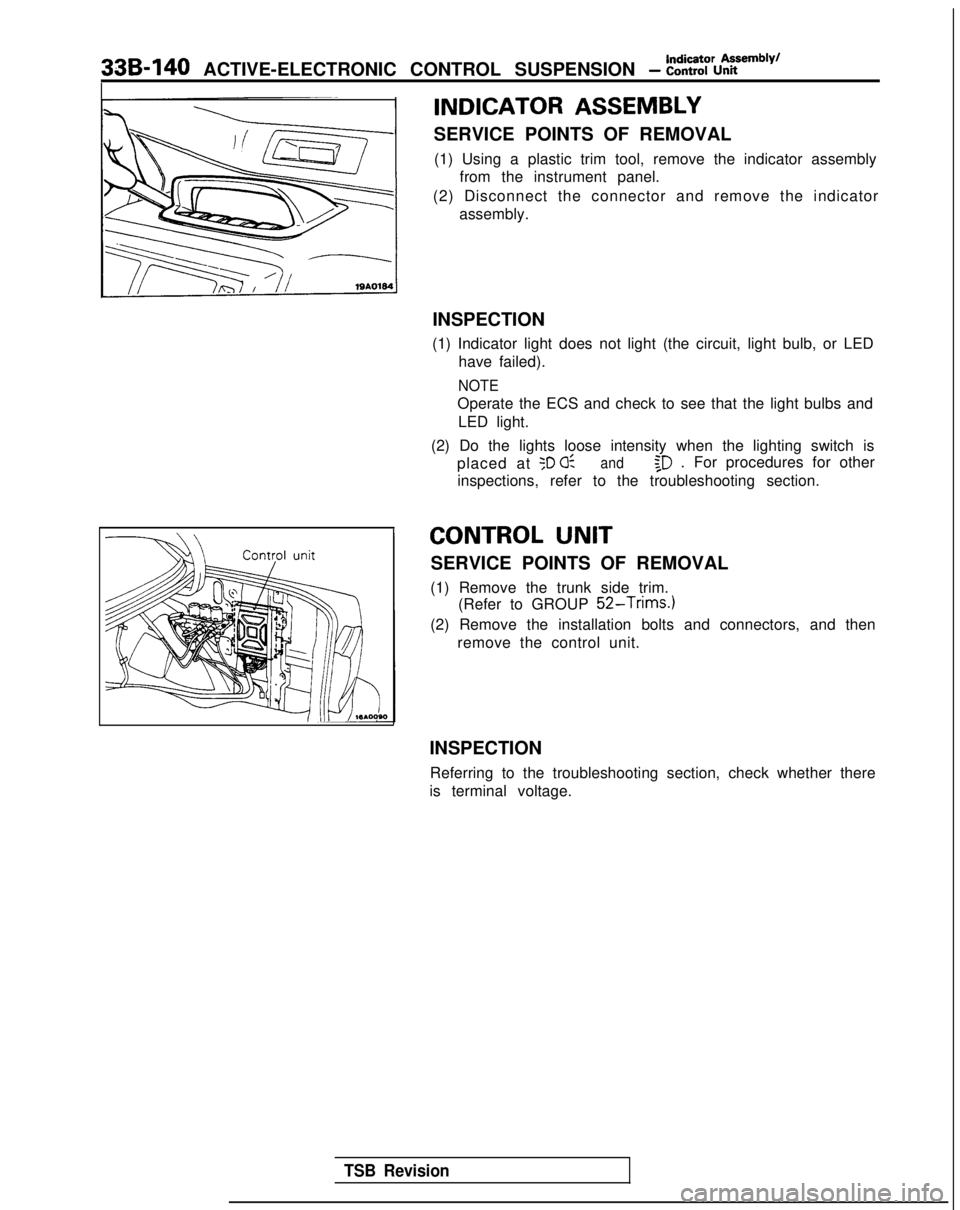
338-140 ACTIVE-ELECTRONIC CONTROL SUSPENSION - t:%%%=mb’y’
INDICATOR ASSEMBLY
SERVICE POINTS OF REMOVAL(1) Using a plastic trim tool, remove the indicator assembly from the instrument panel.
(2) Disconnect the connector and remove the indicator assembly.
INSPECTION
(1) Indicator light does not light (the circuit, light bulb, or LED have failed).
NOTE
Operate the ECS and check to see that the light bulbs and
LED light.
(2) Do the lights loose intensity when the lighting switch is placed at
50 0:and$D . For procedures for other
inspections, refer to the troubleshooting section.
CONTROL UNIT
SERVICE POINTS OF REMOVAL
(1) Remove the trunk side trim. (Refer to GROUP
52-Trims.)
(2) Remove the installation bolts and connectors, and then
remove the control unit.
INSPECTION Referring to the troubleshooting section, check whether there
is terminal voltage.
TSB Revision
Page 1080 of 1273
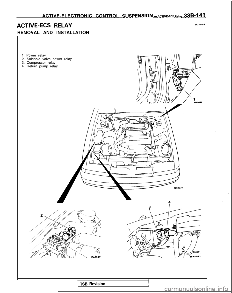
ACTIVE-ELECTRONIC CONTROL SUSPENSlON
- ACTIVE-ECS Relay 338-141
ACTIVE-ECS RELAY-VA-A
REMOVAL AND INSTALLATION
I, Power relay
2. Solenoid valve power relay
3. Compressor relay
4. Return pump relay
TSB RevisionI