MITSUBISHI GALANT 1989 Service Repair Manual
Manufacturer: MITSUBISHI, Model Year: 1989, Model line: GALANT, Model: MITSUBISHI GALANT 1989Pages: 1273, PDF Size: 37.62 MB
Page 181 of 1273
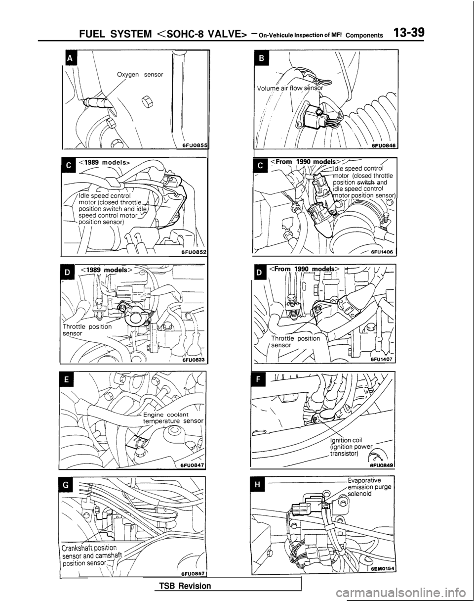
FUEL SYSTEM
Oxygen sensor
1<19& &odekw
sensor
,,< \;F”O85:
:Frory zy models>7-motor (closed
throttle sition
switch and
or
Dositionsensor)
1;’Y/\l IV/A 6FU;4061
1\
6FUO8571\ \I / /
TSB Revision
Page 182 of 1273
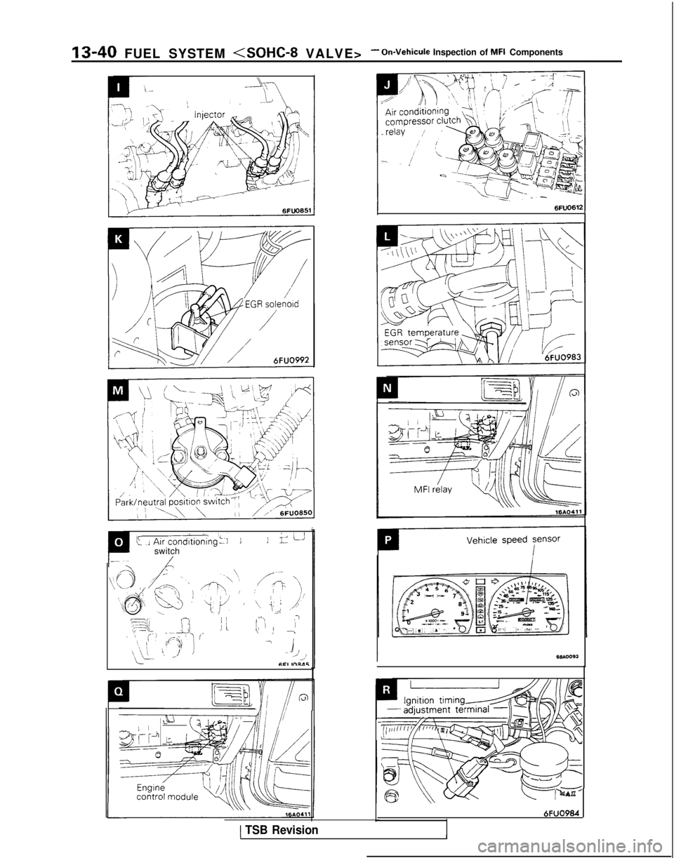
13-40 FUEL SYSTEM
k J Au
condltioning’~l11iz ii
switch/
\\O /r-j
@$ Q I)
RF7 ;;AJ’
,;I \, _Ii
,--\y-,
,‘c/ ’
ili-
/---:P ‘\\
‘\‘\ i,; ,,/‘I
(L ,’.I?
\’ ! ,’
- A
/’A’fCI ,nl‘lS
:/r11,r/lill’“‘I I,, ,1,[bi
2%.
6FUO984
1 TSB Revision1
Page 183 of 1273
FUEL SYSTEM
Ciaarette
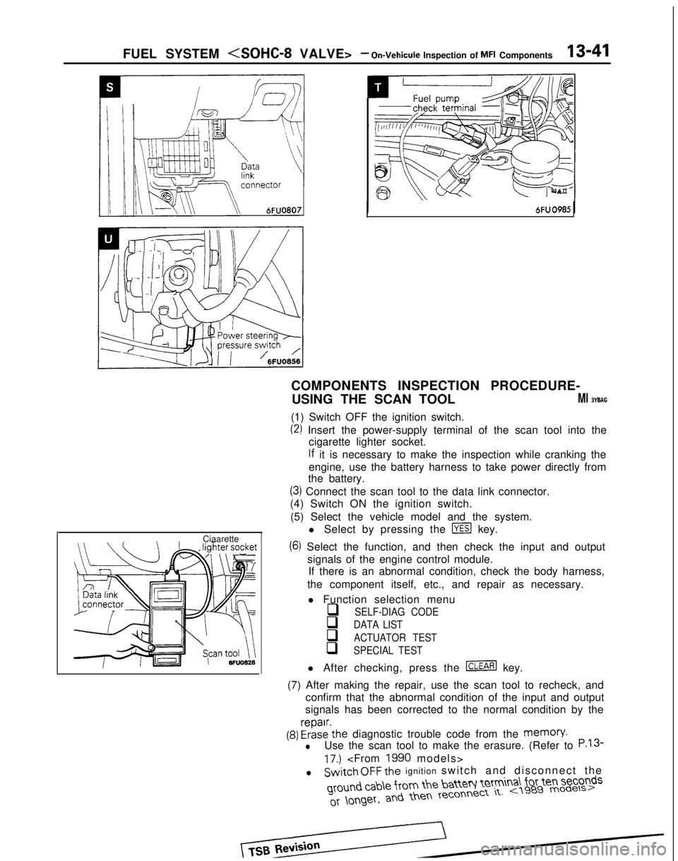
COMPONENTS INSPECTION PROCEDURE-
USING THE SCAN TOOL
Ml BYBAG
(1) Switch OFF the ignition switch.
(2) Insert the power-supply terminal of the scan tool into the cigarette lighter socket.
lf it is necessary to make the inspection while cranking the
engine, use the battery harness to take power directly from
the battery.
(3) Connect the scan tool to the data link connector.
(4) Switch ON the ignition switch.
(5) Select the vehicle model and the system. l Select by pressing the
m key.
(6) Select the function, and then check the input and outputsignals of the engine control module.If there is an abnormal condition, check the body harness,
the component itself, etc., and repair as necessary.
l Function selection menu
q SELF-DIAG CODE
q DATA LIST
q ACTUATOR TEST
q SPECIAL TEST
l After checking, press the m key.
(7) After making the repair, use the scan tool to recheck, and confirm that the abnormal condition of the input and output
signals has been corrected to the normal condition by the
(9) FrizE’the diagnostic trouble code from the memory.
lUse the scan tool to make the erasure. (Refer to P.13
17.)
lSwitch OFF the ignition switch and disconnect the ground
cab\e from the batteq Ie’tm
a\ for ten seconds
Page 184 of 1273
13-42 FUEL SYSTEM
(9) Switch OFF the ignition switch. (10)Disconnect
the scan tool. (11)Restart
the engine and perform a driving test, etc. to
confirm that the malfunction has been corrected.
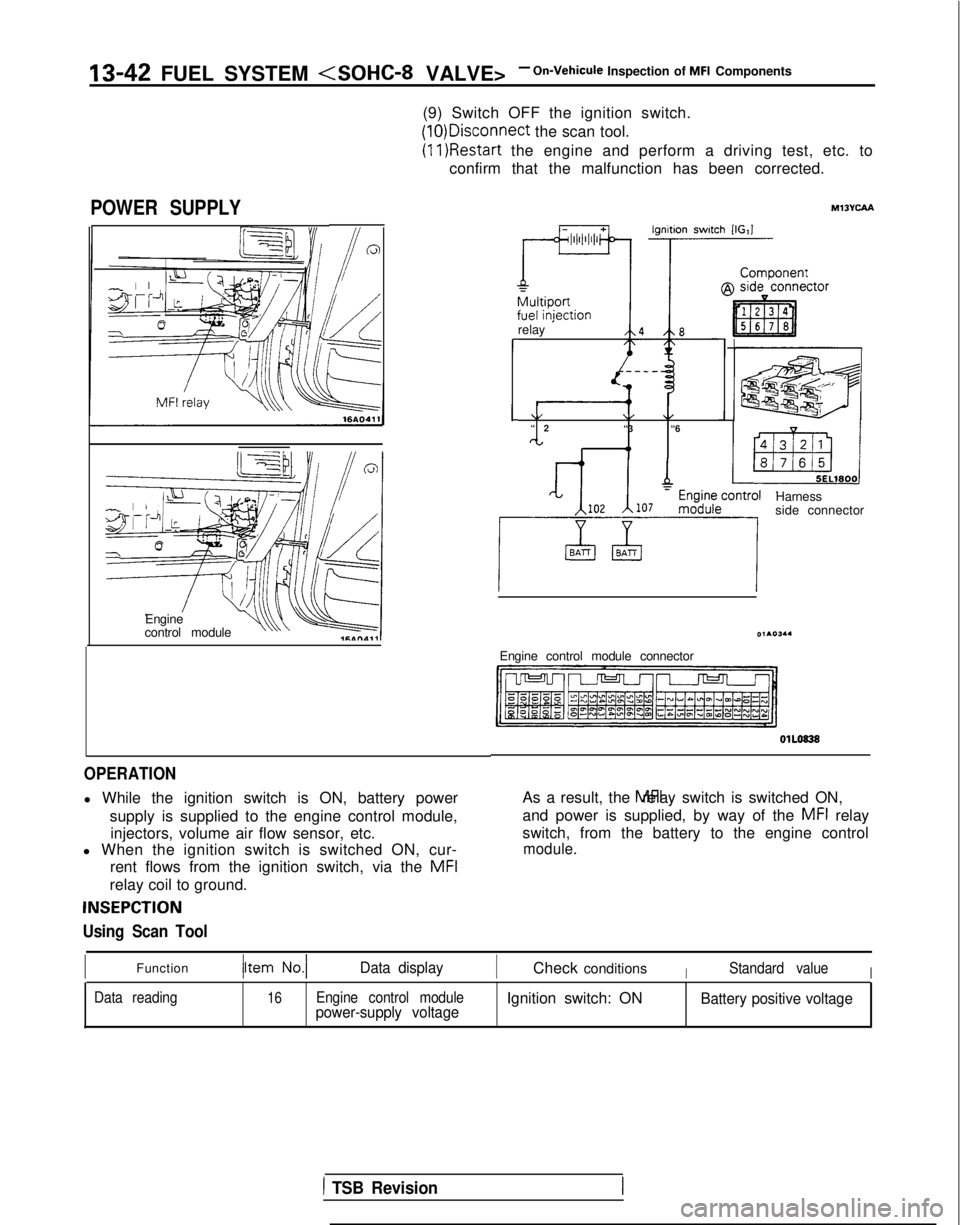
POWER SUPPLY
Engine
control moduleu\\ v
OPERATION
l While the ignition switch is ON, battery power
supply is supplied to the engine control module,injectors, volume air flow sensor, etc.
l When the ignition switch is switched ON, cur-
rent flows from the ignition switch, via the MFI
relay coil to ground.
INSEPCTION
Using Scan Tool
relay ’
\/\/\/“
2
“3 “6
CL I 4,
Harness
side connector
Engine control module connector OlLO838
As a result, the MFI relay switch is switched ON,
and power is supplied, by way of the
MFI relay
switch, from the battery to the engine control
module.
IFunctionData displayICheck conditionsIStandard valueI
Data reading16Engine control modulepower-supply voltageIgnition switch: ONBattery positive voltage
1 TSB Revision
Page 185 of 1273
FUEL SYSTEM
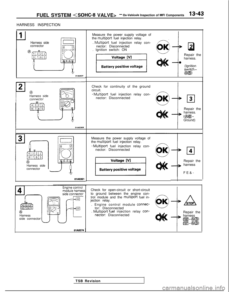
HARNESS INSPECTION
Harness sideconnector
Measure the power supply voltage of
the multiport fuel injection relay.
.
Multiport fuel injection relay con-
nector: Disconnected
. Ignition switch: ON
q2
Check for continuity of the groundIcircuit.
* Multiport fuel injection relay con-
nector: Disconnected
Repair the
harness.
VBEil-Ground)
J
TSB Revision
@Harness side
connector Repair the
harness.
l
(Ignition
switch-
@5)
OlA0361
Measure the power supply voltage of
the multiport fuel injection relay.
* Multiport fuel injection relay con-
nector: Disconnected
El4
Repair the
harness
FE&
-
@Harness
side connector Check for open-circuit or short-circuit
to ground between the engine con-
trol module and the
multiport fuel in-
jection relay.
. Engine control module connec-
tor: Disconnected
.
Multiport fuel injection relay con-
nectar:
Disconnected Repair the
harness
llEW&Bl)
llIEl-@5)
Page 186 of 1273
‘13-44 FUEL SYSTEM
EC1163
When applying battery voltage directly, make sure that it
is applied to correct terminal. Otherwise, the relay could
be damaged.
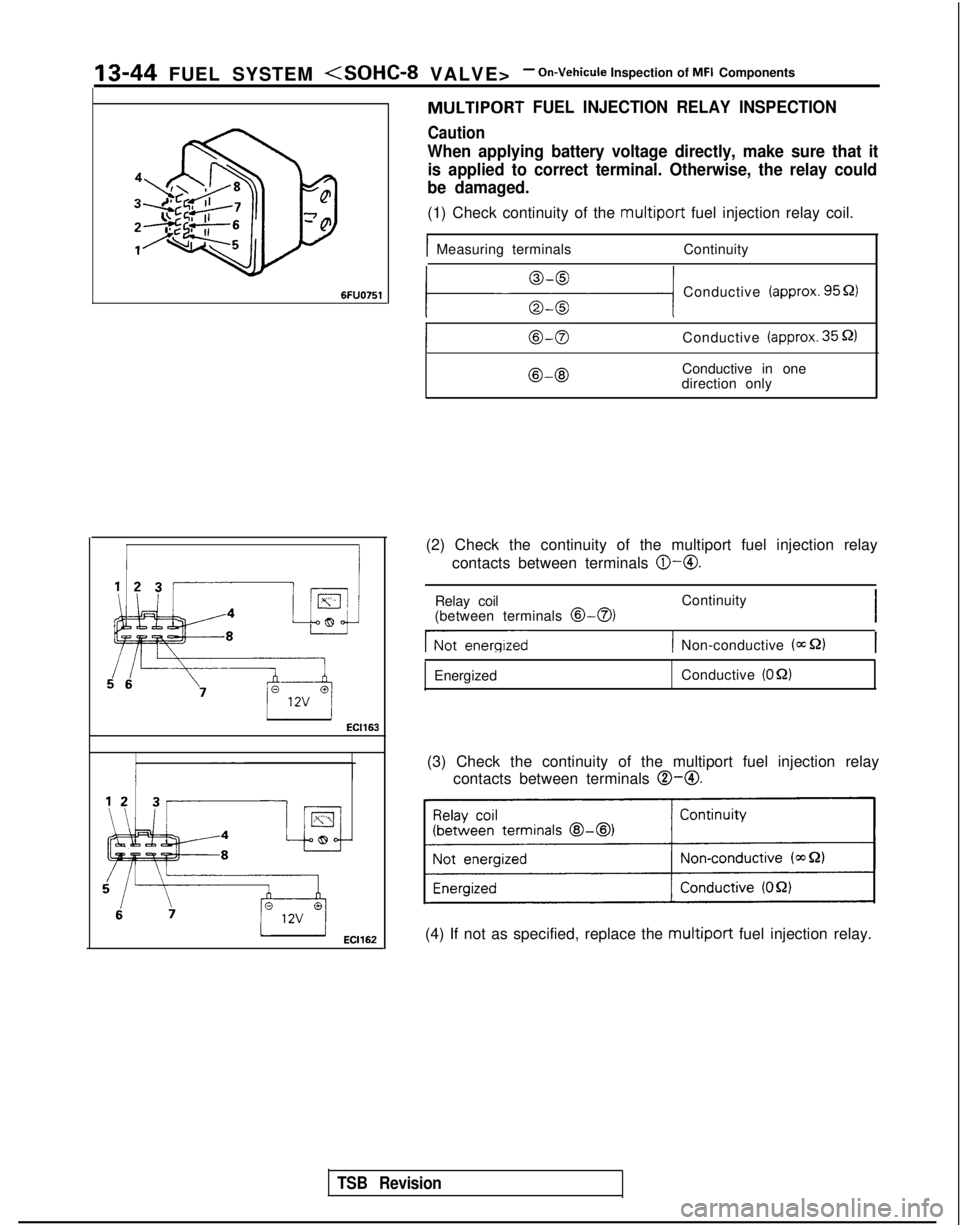
(1) Check continuity of the multiport fuel injection relay coil.
IMeasuring terminals Continuity
MULTIPORT FUEL INJECTION RELAY INSPECTION
Caution
111 Conductive (approx. 9551)
Conductive (approx. 35 52)
@-@IConductive in one
direction only
(2) Check the continuity of the multiport fuel injection relay contacts between terminals
@-@.
TSB Revision
Relay coil
(between terminals @>-a)Continuity
I
Gienergized1 Non-conductive (=S2)
Energized Conductive (OQ)
(3) Check the continuity of the multiport fuel injection relay
contacts between terminals
0-O.
(4) If not as specified, replace the multiport fuel injection relay.
Page 187 of 1273
FUEL .SYSTEM
Inspection of MFI Components13-45
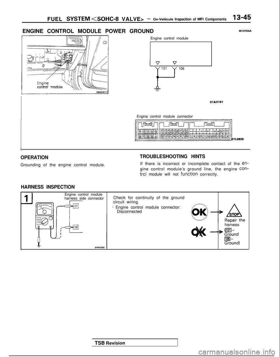
ENGINE CONTROL MODULE POWER GROUND MlJYDAA
control module Engine control module
p7 v
101
F
106
Engine control module connector
01A0191
OlL0838
1
OPERATION
Grounding of the engine control module.
TROUBLESHOOTING HINTS
If there is incorrect or incomplete contact of the en-
aine control module’s ground line, the engine con-
?rol module will not function correctly.
HARNESS INSPECTION
TSB Revision
IJ
Engine control module
harness side connector Check for continuity of the ground
circuit wiring.
* Engine control module connector: Disconnected
harness
--* !!%nd
Rind)
Page 188 of 1273
13-46 FUEL SYSTEM
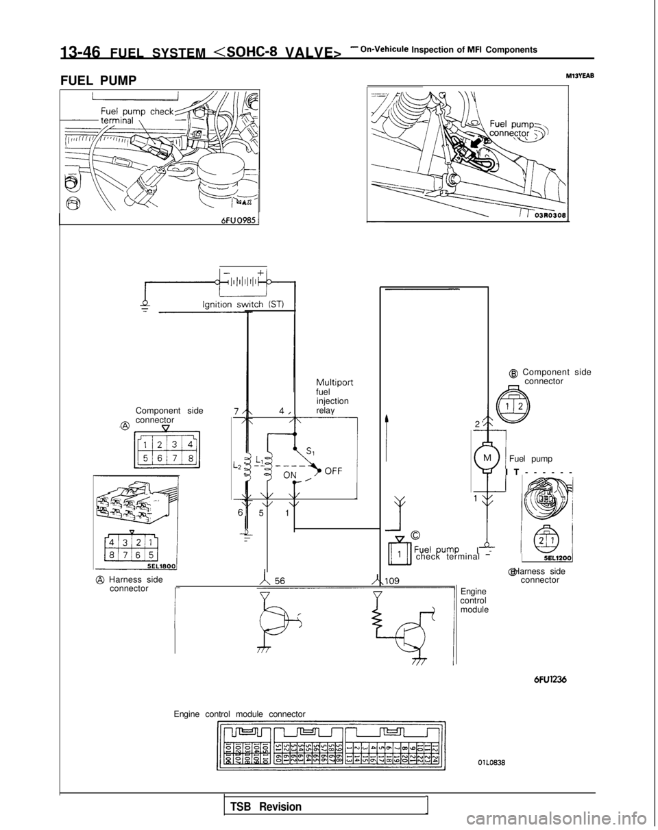
FUEL PUMP
MlBYEAB
@ Component side connector
-
\
1Fuel pump M
$
1
I
-
Multiportfuel
injection
relay
Component side
7/-/
L2 :<
\
6’
_!
4,
@connector,
I-~ i1SlLl”’-------.,\OFF I OIL
,’e-
\/ \/1\/ \/5 1 2
’
-
I
IT-----
-
1!
check terminal -5EL1200j
Engine
control module @ Harness side
connector
@ Harness side
connector
I
6FU1236
Engine control module connector OlLO838
TSB RevisionI
Page 189 of 1273
FUEL SYSTEM
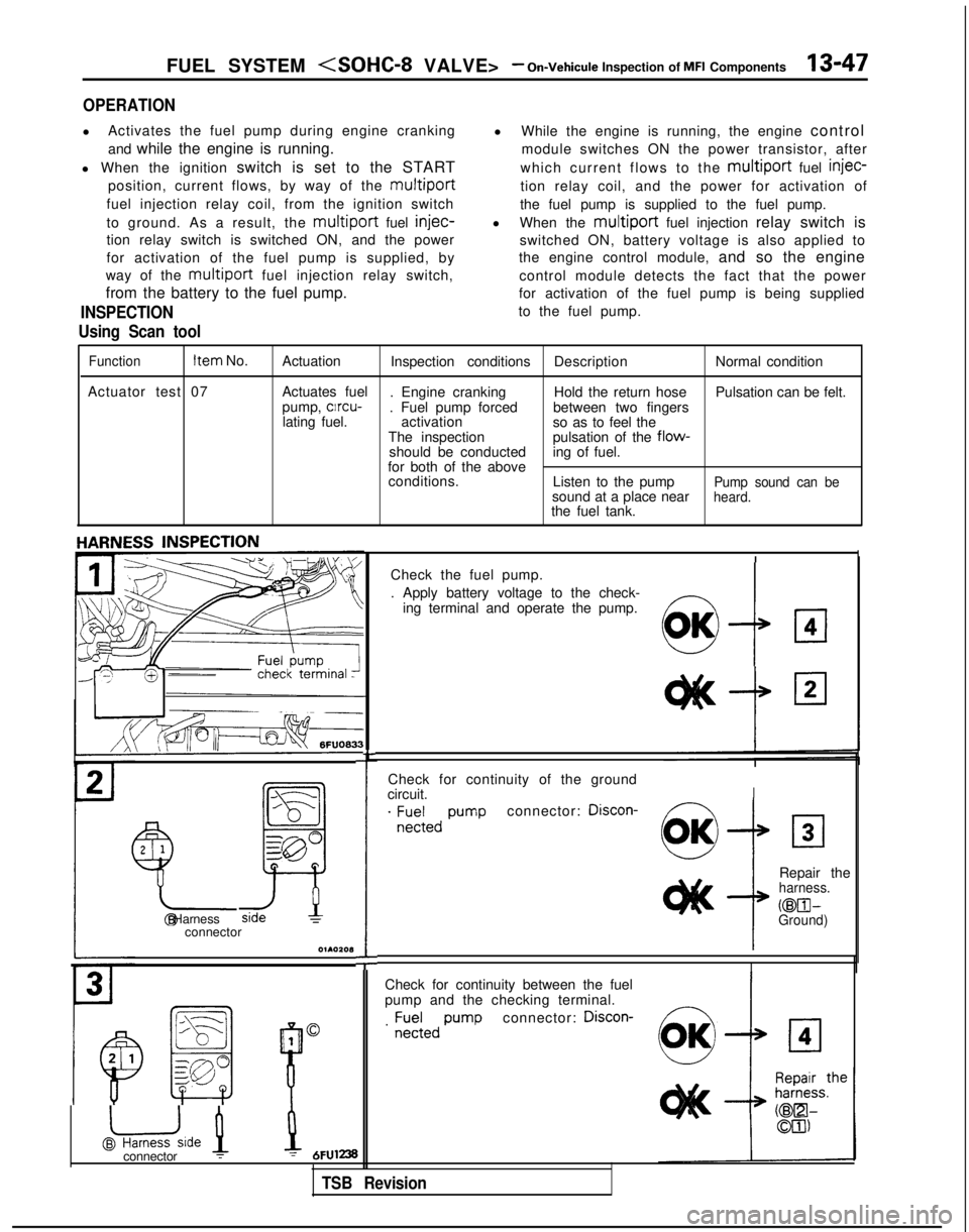
OPERATION
l
Activates the fuel pump during engine cranking
and while the engine is running.
l When the ignition switch is set to the START
position, current flows, by way of the
multiport
fuel injection relay coil, from the ignition switch
to ground. As a result, the
multiport fuel injec-
tion relay switch is switched ON, and the power
for activation of the fuel pump is supplied, by
way of the
multiport fuel injection relay switch,
from the battery to the fuel pump.
INSPECTION
Using Scan tool
l While the engine is running, the engine control
module switches ON the power transistor, after
which current flows to the
multiport fuel injec-
tion relay coil, and the power for activation of
the fuel pump is supplied to the fuel pump.
l When the
multiport fuel injection relay switch is
switched ON, battery voltage is also applied to
the engine control module, and so the engine
control module detects the fact that the power
for activation of the fuel pump is being supplied
to the fuel pump.
Function Item
No.
Actuation Inspection conditions DescriptionNormal condition
Actuator test 07 Actuates fuel
. Engine cranking Hold the return hosePulsation can be felt.
pump, clrcu-
. Fuel pump forced between two fingers
lating fuel. activation
so as to feel the
The inspection pulsation of the
flow-should be conducteding of fuel.
for both of the above conditions. Listen to the pump
Pump sound can besound at a place nearheard.the fuel tank.
Check for continuity of the ground
circuit.
I
. ;E;;,, pumpconnector: Discon-
2
1
Y-
!
Repair theharness.
@El- @ HarnessGround)connector
O~AOZOl3
I
Check for continuity between the fuel
pump and the checking terminal.
connector: Discon-
1
@uide 1
B
0. ;;;;,,
pump
L
Check the fuel pump.
. Apply battery voltage to the check-
ing terminal and operate the pump.
!I:7
OK
connector :1 = 6FUl238
TSB Revision
Page 190 of 1273
13-48 FUEL SYSTEM
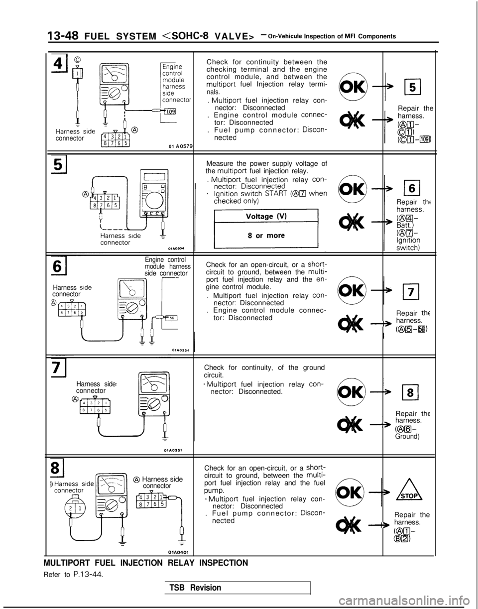
Check for continuity between the
checking terminal and the engine
control module, and between the
multiport fuel Injection relay termi-nals.
connector
01 A0579
.
Multiport fuel injection relay con-
nector: Disconnected
. Engine control module connec-
tor: Disconnected
. Fuel pump connector: Discon-
netted
Repair the
harness.
Measure the power supply voltage of
the
multiport fuel injection relay.
.
Multiport fuel injection relay con-
Harness sideconnector
Engine control
module harnessCheck for an open-circuit, or a short-
side connectorcircuit to ground, between the multi-port fuel injection relay and the en-
gine control module.
. Multiport fuel injection relay con-
nectar:
Disconnected
. Engine control module connec-
tor: Disconnected Repair
the-+ harness.
(@a-8)
Harness side
connector
@
Check for continuity, of the ground
circuit.
- Multiport fuel injection relay con-
nectar:
Disconnected.
Repair
theharness.
a vmil-Ground)
@ Harness sideconnector
Check for an open-circuit, or a short-circuit to ground, between the multi-port fuel injection relay and the fuel
w-we Multiport fuel injection relay con-
nector: Disconnected
. Fuel pump connector: Discon-
nettedRepair the-+ harness.
GilIl-@El)T
OlA0401
MULTIPORT FUEL INJECTION RELAY INSPECTION
Refer to P.13-44.
TSB Revision