MITSUBISHI GALANT 1989 Service Repair Manual
Manufacturer: MITSUBISHI, Model Year: 1989, Model line: GALANT, Model: MITSUBISHI GALANT 1989Pages: 1273, PDF Size: 37.62 MB
Page 191 of 1273
FUEL SYSTEM
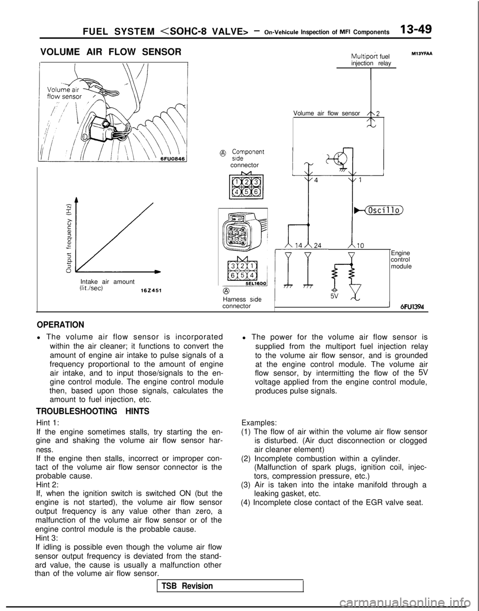
VOLUME AIR FLOW SENSOR
@ ;;vonent
connector
Intake air amount
(Wsec)162451
Multipoh fuel
injection relay
Volume air flow sensor
/\2/\N
Harness side
connector
IHjhcillo)
1.10
f-i5V
Engine
control
module
MlOYFAA
J 6FU1394
OPERATION
l The volume air flow sensor is incorporated
within the air cleaner; it functions to convert the
amount of engine air intake to pulse signals of a
frequency proportional to the amount of engine air intake, and to input those/signals to the en-
gine control module. The engine control module
then, based upon those signals, calculates the amount to fuel injection, etc.
TROUBLESHOOTING HINTS
Hint 1:
If the engine sometimes stalls, try starting the en-
gine and shaking the volume air flow sensor har-
ness.
If the engine then stalls, incorrect or improper con-
tact of the volume air flow sensor connector is the probable cause.
Hint 2:
If, when the ignition switch is switched ON (but the
engine is not started), the volume air flow sensor
output frequency is any value other than zero, a
malfunction of the volume air flow sensor or of the
engine control module is the probable cause. Hint 3:
If idling is possible even though the volume air flow
sensor output frequency is deviated from the stand-
ard value, the cause is usually a malfunction other
than of the volume air flow sensor. l The power for the volume air flow sensor is
supplied from the multiport fuel injection relay
to the volume air flow sensor, and is grounded at the engine control module. The volume air
flow sensor, by intermitting the flow of the
5V
voltage applied from the engine control module,
produces pulse signals.
Examples:
(1) The flow of air within the volume air flow sensor is disturbed. (Air duct disconnection or clogged
air cleaner element)
(2) Incomplete combustion within a cylinder. (Malfunction of spark plugs, ignition coil, injec-
tors, compression pressure, etc.)
(3) Air is taken into the intake manifold through a leaking gasket, etc.
(4) Incomplete close contact of the EGR valve seat.
TSB Revision
Page 192 of 1273
13-50 FUEL SYSTEM
INSPECTION
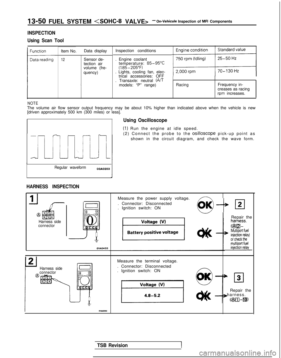
Using Scan Tool
Item No. Data display Inspection conditions
12Sensor de-
tection air
volume (fre-
quency) . Engine coolant
temperature: 85-95°C(185-205°F). Lights, cooling fan, elec-
trical accessories: OFF
. Transaxle: neutral (iVT
models: “P” range)
RacingFrequency in-
creases as racing
rpm increases.
NOTEThe volume air flow sensor output frequency may be about 10% higher than\
indicated above when the vehicle is new [driven approximately 500 km (300 miles) or less].
Regular waveform 03A0203
HARNESS INSPECTION
@
Harness sideconnector
6
0-0
~
0
=
Using Oscilloscope
(1) Run the engine at idle speed.
(2) Connect the probe to the
osilloscope pick-up point a
s
shown in the circuit diagram, and check the wave form.
Measure the power supply voltage.
. Connector: Disconnected
. Ignition switch: ON
--P
IRepair the
Harness sideconnector
Measure the terminal voltage.
. Connector: Disconnected
. Ignition switch: ON ~
0
OK’ 30
Repair the
harness
.
cm-an)
TSB Revision1
Page 193 of 1273
FUEL SYSTEM
Harness side
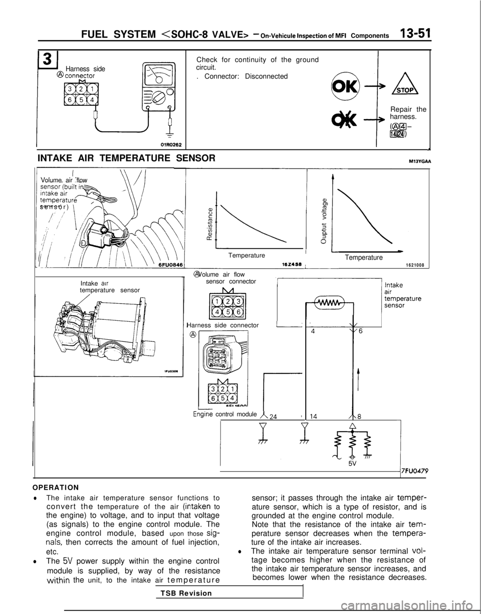
Check for continuity of the ground
circuit.
. Connector: Disconnected
@+A
Repair the
harness.
@3l-FiBill
J
INTAKE AIR TEMPERATURE SENSORMlJYGAA
Volume air flow
sensor)
\
Intake air
temperature sensor Temperature 16Z456
L- @ Volume air flow
sensor connector
Harness side connector
I
rEGine control module A 24,
wTemperature1621008
&5V1
7FUO479
OPERATION
lThe intake air temperature sensor functions to sensor; it passes through the intake air temper-
convert the temperature of the air (intaken to
ature sensor, which is a type of resistor, and is
the engine) to voltage, and to input that voltage grounded at the engine control module.
(as signals) to the engine control module. The Note that the resistance of the intake air
tem-
engine control module, based upon those sig-perature sensor decreases when the tempera-
nals, then corrects the amount of fuel injection,
ture of the intake air increases.
etc.lThe intake air temperature sensor terminal vol-
lThe 5V power supply within the engine control
tage becomes higher when the resistance of
module is supplied, by way of the resistance the intake air temperature sensor increases, and
within the unit, to the intake air
temperatur
e
becomes lower when the resistance decreases.
TSB Revision
Page 194 of 1273
13-52 FUEL SYSTEM
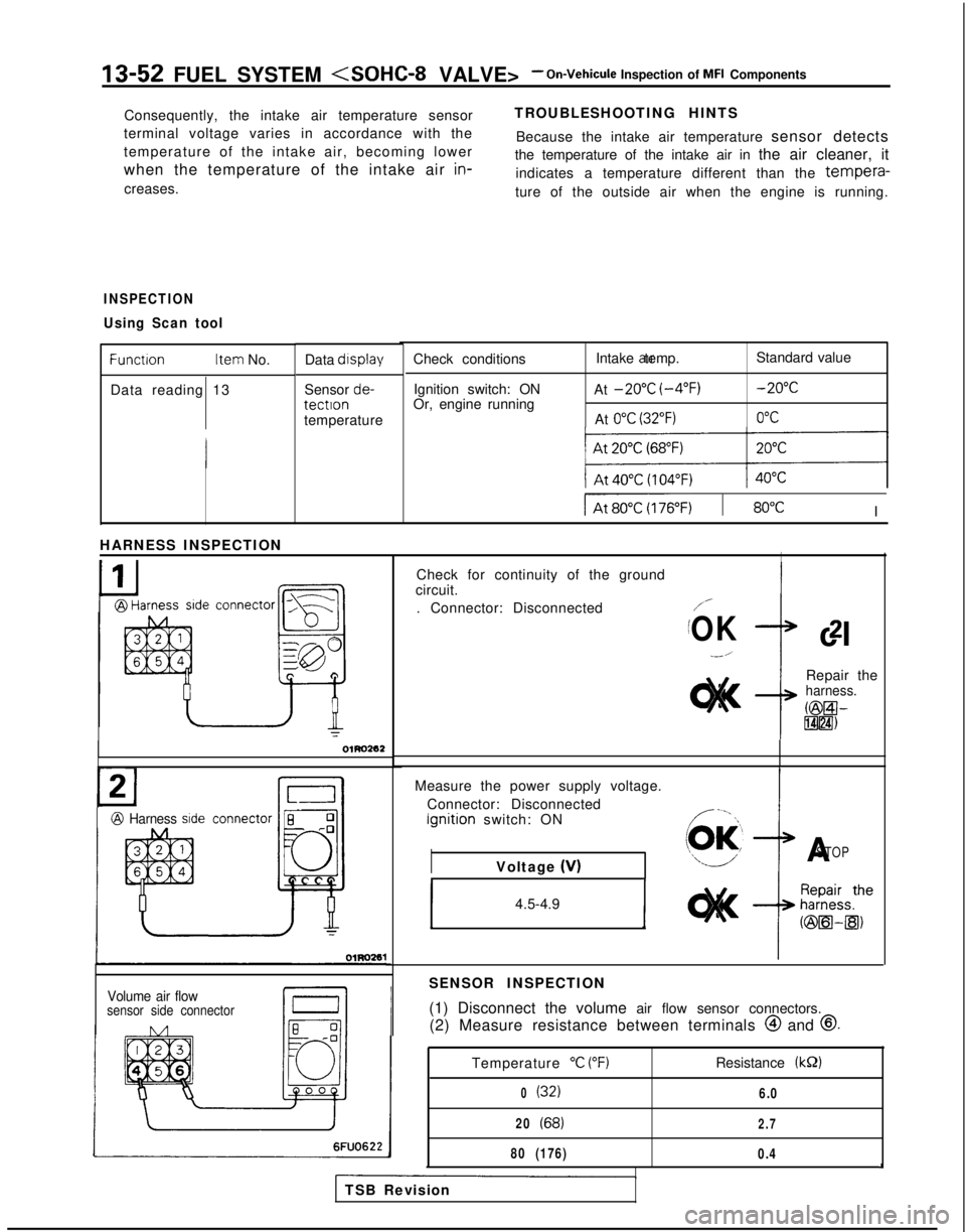
Consequently, the intake air temperature sensor
terminal voltage varies in accordance with the
temperature of the intake air, becoming lower
when the temperature of the intake air in-
creases. TROUBLESHOOTING HINTS
Because the intake air temperature sensor detects
the temperature of the intake air in the air cleaner, it
indicates a temperature different than the
tempera-
ture of the outside air when the engine is running.
INSPECTION
Using Scan tool
Function Item
No.
Data reading 13 Data display
Sensor de-tectlontemperature
connector
-,-S=
[
a
ry:
EQO
n
OlRO262
Check conditions
Ignition switch: ON
Or, engine running Intake air temp.
At
-20°C (-4°F)
At 0°C (32°F)
Standard value -20°C
0°C
IAt60~) I 80°CI
HARNESS INSPECTION
I
@ Harness sideconnector 8 0-0
Jill
I54
T
Volume air flowsensor side connector
Check for continuity of the ground
circuit.
. Connector: Disconnected
/-
/OKcl2
--/
Repair theharness.
@El-lT$lH)
IMeasure the power supply voltage.
Connector: Disconnected Ignition
switch: ON
IASTOPVoltage (V)
1 4.5-4.9 1
SENSOR INSPECTION
(1) Disconnect the volume air flow sensor connectors.
(2) Measure resistance between terminals @
and
@.
6FUO622
Temperature “C (“F)
0(32)
20(68)
80 (176)
Resistance (kS2)
6.0
2.7
0.4A
TSB Revision
Page 195 of 1273
FUEL SYSTEM
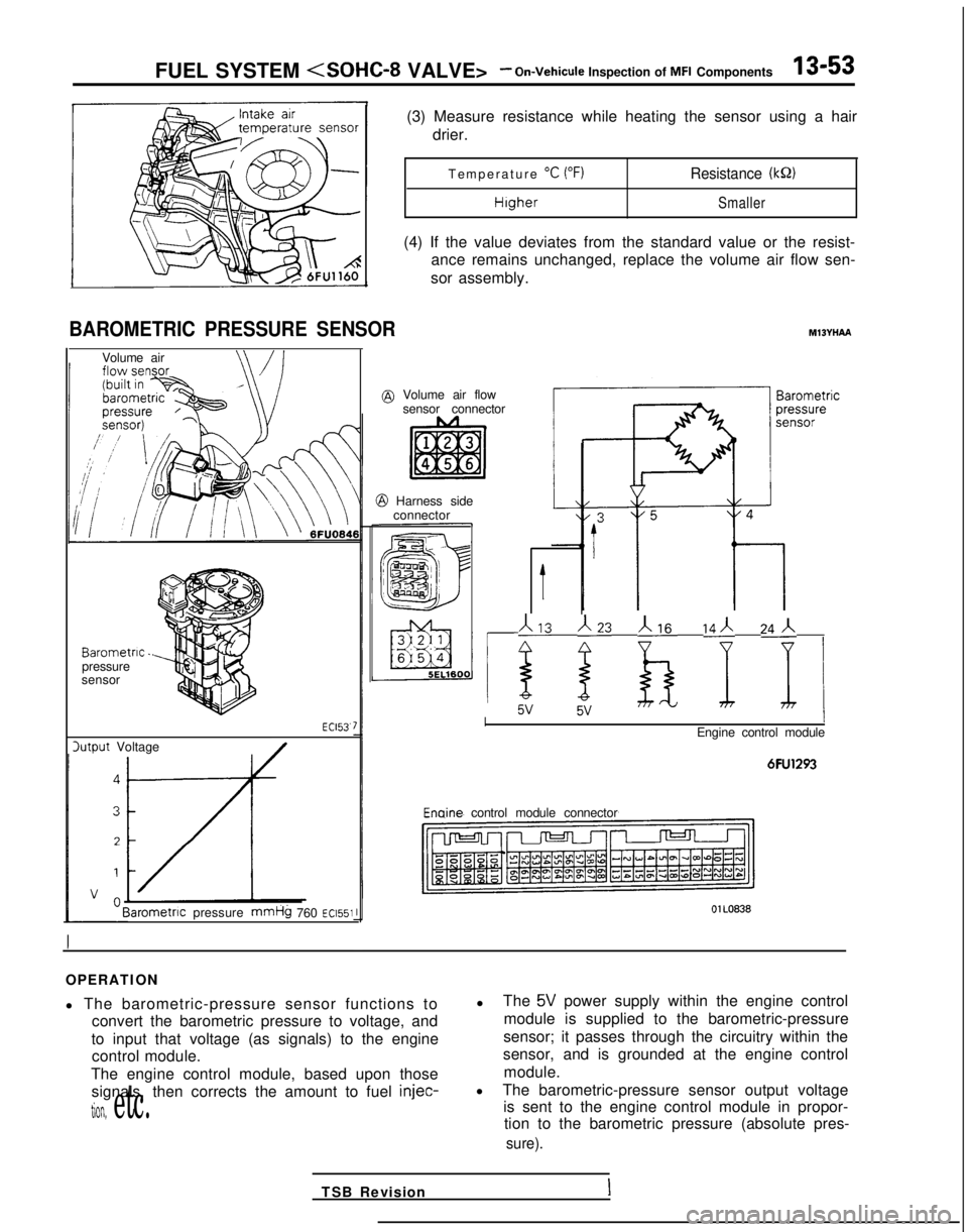
BAROMETRIC PRESSURE SENSOR
Volume air
Barometric.pressure
sensor
lutput Voltage ECl53.
Barometnc
pressure
mmHg 760 ~~1551
(3) Measure resistance while heating the sensor using a hair
drier.
Temperature
“C (“F)Resistance (kQ)
HigherSmaller
(4) If the value deviates from the standard value or the resist-
ance remains unchanged, replace the volume air flow sen-
sor assembly.
MlBYHAA
@ Volume air flow sensor connector
@ Harness sideconnector
t
113 j23 b ‘I 24j i
IEngine control module
6FU1293 Enaine
control module connector
OlL0838
OPERATION
l The barometric-pressure sensor functions to
convert the barometric pressure to voltage, and
to input that voltage (as signals) to the engine control module.
The engine control module, based upon those signals, then corrects the amount to fuel injec-
tion, etc.
l
The 5V power supply within the engine control
module is supplied to the barometric-pressure
sensor; it passes through the circuitry within the
sensor, and is grounded at the engine control
module.
l The barometric-pressure sensor output voltage
is sent to the engine control module in propor-tion to the barometric pressure (absolute pres-
sure).
TSB RevisionI
Page 196 of 1273
13-54 FUEL SYSTEM
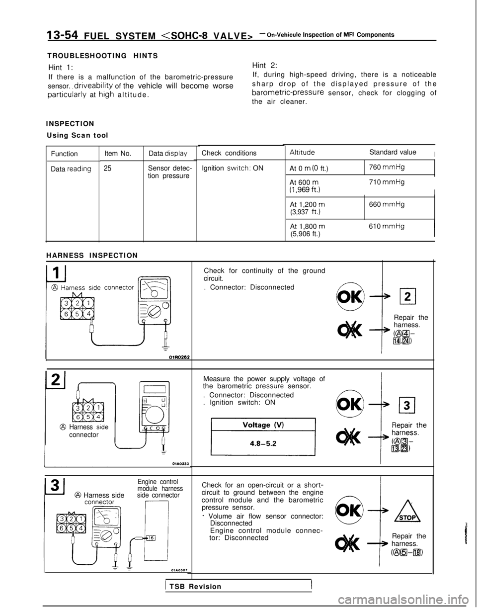
TROUBLESHOOTING HINTS Hint 1: Hint 2:
If there is a malfunction of the barometric-pressure If, during high-speed driving, there is a noticeable
sensor,
driveability of the vehicle will become worse sharp drop of the displayed pressure of th
e
barometric-rxessure sensor, check for clogging ofparticularly at hig’h altitude
.
the air cleaner.
INSPECTION Using Scan tool
AltitudeStandard valueICheck conditions
Item No. Data display
25Sensor detec-
tion pressure
Function
Data reading
Ignition switch: ON
At 0 m (0 ft.) 760 mmHg
At 600
m(1,969ft.j710 mmHg
I
At 1,200 m660
mmHg(3,937
ft.)
At 1,800
m(5,906 ft.) 610 mmHgI
HARNESS INSPECTION
Check for continuity of the ground
circuit.
. Connector: Disconnected
connector
L,?
la
Fi
gg-CI
e
Repair the
harness.
KBEil-IBHZI)
Measure the power supply voltage of
the barometric oressure
sensor.
. Connector: Disconnected
. Ignition switch: ON
Harness side
connector
Check for an open-circuit or a short-circuit to ground between the engine
control module and the barometric pressure sensor.
f Volume air flow sensor connector: Disconnected
Engine control
module harness
@ Harness sideside connector
Engine control module connec-
tor: Disconnected Repair the
harness.
ozsEl-~)
1 TSB Revision
Page 197 of 1273
FUEL SYSTEM
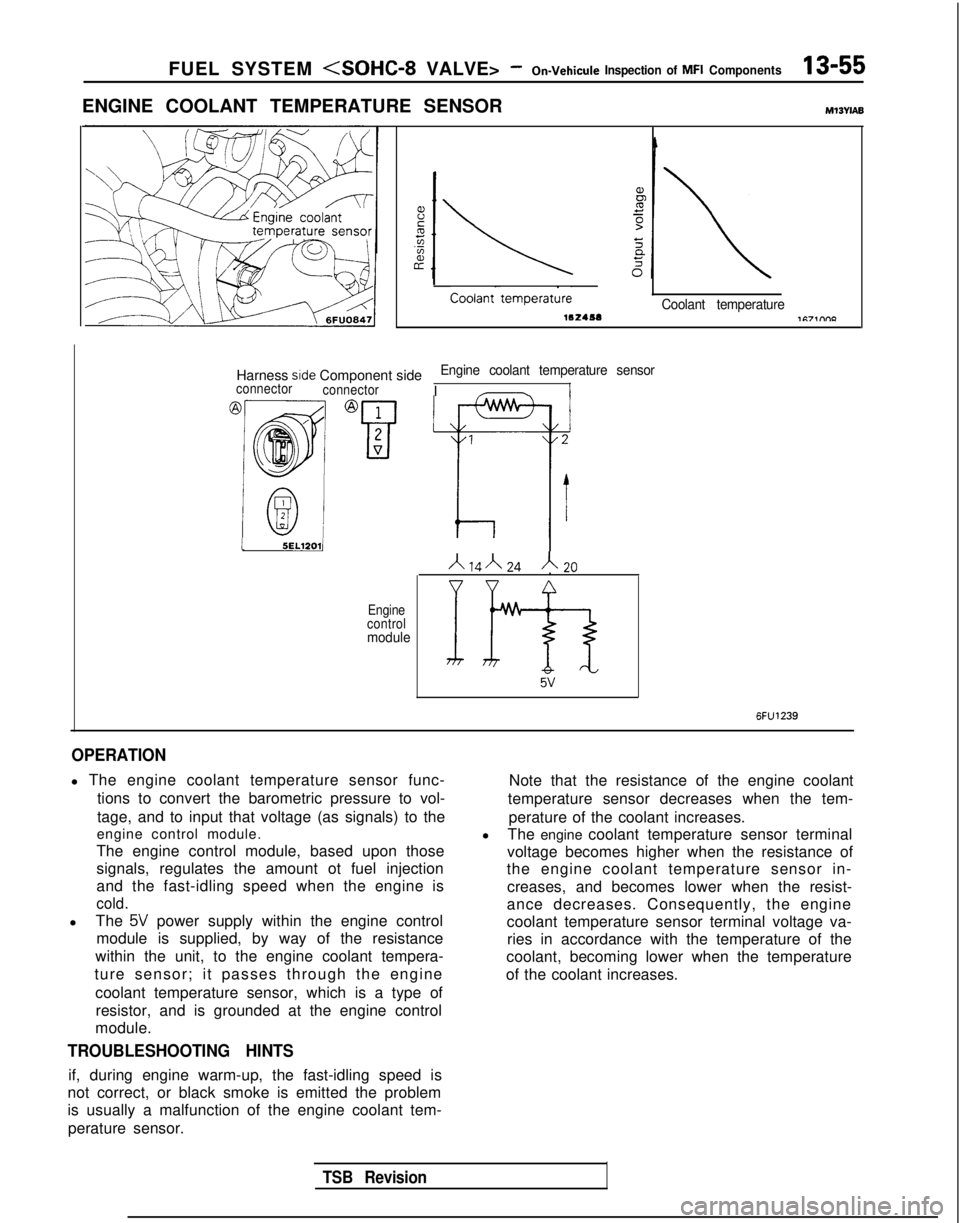
ENGINE COOLANT TEMPERATURE SENSORMl3wAB
Coolant-
tempera&Coolant temperature
Harness side Component sideEngine coolant temperature sensorIconnector
connectorI -
15EL12011I IA14”24A20
Engine
control
module
If9-3 5v
6FU1239
OPERATION
l The engine coolant temperature sensor func-
tions to convert the barometric pressure to vol-
tage, and to input that voltage (as signals) to the
engine control module.
The engine control module, based upon those
signals, regulates the amount ot fuel injection
and the fast-idling speed when the engine is
cold.
l The 5V power supply within the engine control
module is supplied, by way of the resistance
within the unit, to the engine coolant tempera-
ture sensor; it passes through the engine
coolant temperature sensor, which is a type ofresistor, and is grounded at the engine control
module.
TROUBLESHOOTING HINTS
if, during engine warm-up, the fast-idling speed is
not correct, or black smoke is emitted the problem
is usually a malfunction of the engine coolant tem-
perature sensor. Note that the resistance of the engine coolant
temperature sensor decreases when the tem-
perature of the coolant increases.
l The engine coolant temperature sensor terminal
voltage becomes higher when the resistance of
the engine coolant temperature sensor in-
creases, and becomes lower when the resist-
ance decreases. Consequently, the engine
coolant temperature sensor terminal voltage va- ries in accordance with the temperature of the
coolant, becoming lower when the temperature
of the coolant increases.
TSB Revision
Page 198 of 1273
13-56 FUEL SYSTEM
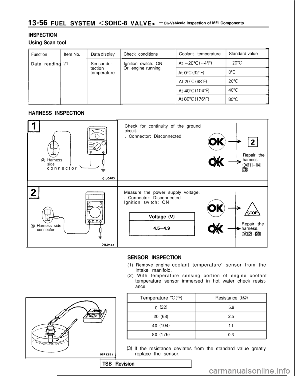
INSPECTION
Using Scan tool
FunctionItem No.
Data reading
-*LI
Data display
Sensor de-
tection
temperature
HARNESS INSPECTION
connector OlLO461Check conditions
Ignition switch: ON
Or, engine running Coolant temperature
Standard value
At
-20°C (-4°F)-20°C
At 0°C (32°F)0°C I
At
20°C (68°F)20°C
connector - Ic
OIL0463L
-16R1251
Temperature “C (“F)Resistance (kS2)
0 (32)5.9
20 (68)2.5
40 (104)1.1
80 (176) 0.3
(3) If the resistance deviates from the standard value greatly
replace the sensor.
J
TSB Revision
At 40°C (104°F)40°C
At 80°C (176°F)80°C
1
Check for continuity of the ground
circuit.
. Connector: Disconnected
Repair the
harness.
b&XII-@.
lm
Measure the power supply voltage.I. Connector: Disconnected
Ignition switch: ONVoltage
(VI
SENSOR INSPECTION
(1) Remove engine coolant temperature’ sensor from the
intake manifold.
(2) With temperature sensing portion of engine coolan
t
temperature sensor immersed in hot water check resist-
ance.
Page 199 of 1273
FUEL SYSTEM
INSTALLATION
(1) Apply sealant
3M
NUT locking No.41 71 or equivalent to
threaded portion.
(2) Install engine coolant temperature sensor and tighten it to specified torque.
Sensor tightening torque:
20-40 Nm (15-29 ft.lbs.1
(3) Fasten harness connectors securely
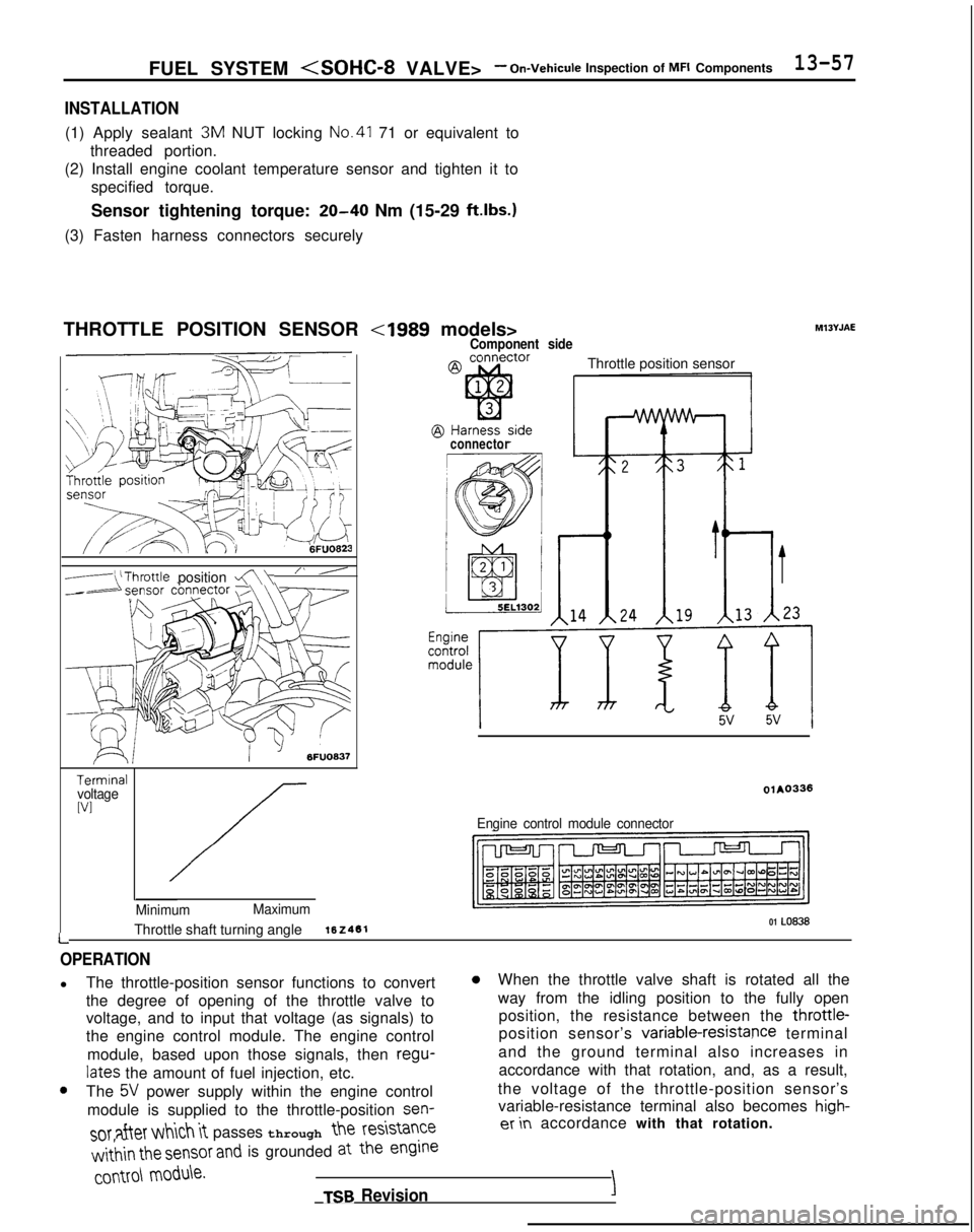
THROTTLE POSITION SENSOR
-(‘Throttle position a\“ ’
6FUO637
TerminalvoltageWI
L
Minimum Maximum01 LO838Throttle shaft turning angle162461
Component side
Throttle position sensor
connector
olAO336
Engine control module connector Ml3YJAE
OPERATION
l
The throttle-position sensor functions to convert0When the throttle valve shaft is rotated all the
the degree of opening of the throttle valve to way from the idling position to the fully open
voltage, and to input that voltage (as signals) to position, the resistance between the throttle-
the engine control module. The engine control position sensor’s variable-resistapce
terminal
module, based upon those signals, then regu-
and the ground terminal also increases in
lates the amount of fuel injection, etc. accordance with that rotation, and, as a result,0The 5V power supply within the engine control
the voltage of the throttle-position sensor’s
module is supplied to the throttle-position sen-
variable-resistance terminal also becomes high-
SOT after which it passes through the
resistanceer in
accordance with that rotation.
w&in the sensor and is grounded at the engine
COMO\
module.
TSB RevisionI
Page 200 of 1273
13-58 FUEL SYSTEM
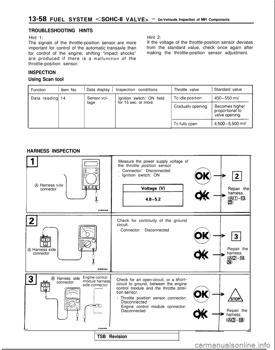
TROUBLESHOOTING HINTS
Hint 1:Hint 2:
The signals of the throttle-position sensor are more If the voltage of the throttle-position sensor deviates
important for control of the automatic transaxle than from the standard value, check once again after
for control of the engine; shifting “impact shocks” making the throttle-position sensor adjustment.
are produced if there is a malfunction of the
throttle-position sensor.
INSPECTION
Using Scan tool
Function/ Item No.1 Data display 1 Inspection conditions1 Throttle valve1 Standard value
Data reading 14 Sensor
vol-tageIgnition switch: ON held
for 15 sec. or more
HARNESS INSPECTION
E q-0
JJ ~
@ Harness side0
connector
@ Harness sideconnector
Harness side
connector
Measure the power supply voltage of
the throttle position sensor.
. Connector:’ Disconnected
. Ignition switch: ON
Check for continuity of the ground
circuit.
Connector: Disconnected
Repair the
harness.
bZilZl-m* &I)
Check for an open-circuit, or a short-
circuit to ground, between the engine
control module and the throttle posi-
. Throttle position sensor connector: Engine control module connector:
Disconnected Repair the
harness.
Fi&TUI-mj
01103611
TSB Revision