MITSUBISHI GALANT 1989 Service Repair Manual
Manufacturer: MITSUBISHI, Model Year: 1989, Model line: GALANT, Model: MITSUBISHI GALANT 1989Pages: 1273, PDF Size: 37.62 MB
Page 221 of 1273
FUEL SYSTEM
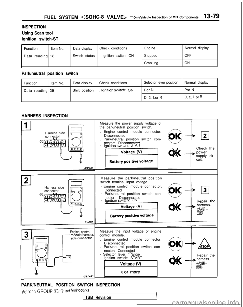
INSPECTION
Using Scan tool
Ignition switch-ST
Function Item No.Data display Check conditions
EngineNormal display
Data reading 18 Switch status
. Ignition switch: ON Stopped
OFF
CrankingON
Park/neutral position switch
Function
Item No.Data display
Check conditions Selector lever position
Normal display
Data reading 29 Shift position
. Ignition
swatch: ON Por NPor N
D, 2, Lor RD, 2, L or R
HARNESS INSPECTION
Harness sideconnector
Engine control
Measure the input voltage of engine
control module.
. Engine control module connector: Disconnected
. Park/neutral position switch con-
nector: Connected
* Selector lever: “P” range
. Ignition switch: START
Voltage (V)
:
1
Y-OlLO42’f
PARK/NEUTRAL POSITION SWITCH INSPECTION
Measure the power supply voltage of
the park/neutral position switch.
. Engine control module connector: Disconnected
. Park/neutral position switch con-
nector: Disconnected
Check the
I+
power
supply cir-
cuit.
Measure the park/neutral position
switch terminal input voltage.
* Engine control module connector: ConnectedPark/neutral position switch con-
nector: Disconnected
8 or more
ASTOP
Repair the
harness.
C@W lIEI)
Refer to GROUP 23-Troubleshooting.
TSB RevisionI
Page 222 of 1273
13-80 FUEL SYSTEM
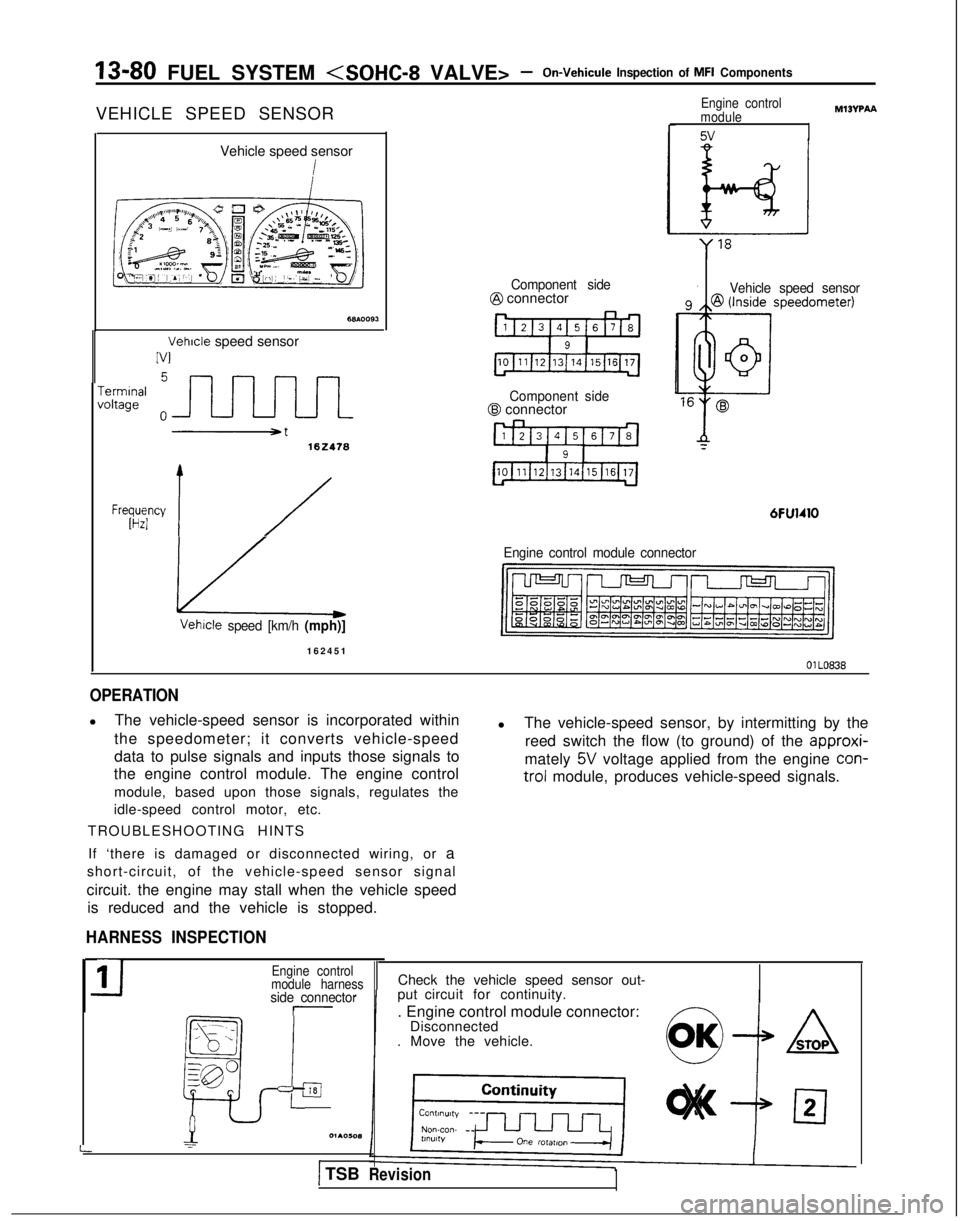
VEHICLE SPEED SENSOR
Vehicle speed sensor
Vehicle speed sensor
IV1
-errnInafoltage
102418
Frwyy 1/
Component side@ connector
Component side@ connector
6FU1410
Engine control
module
5v
MIBVPAA
Vehicle speed sensor
Engine control module connector Vetwle
speed [km/h (mph)]
16245
1
OlLO838
OPERATION
l
The vehicle-speed sensor is incorporated within
the speedometer; it converts vehicle-speed
data to pulse signals and inputs those signals to
the engine control module. The engine control
module, based upon those signals, regulates the
idle-speed control motor, etc.
TROUBLESHOOTING HINTS l
The vehicle-speed sensor, by intermitting by the
reed switch the flow (to ground) of the approxi-
mately
5V voltage applied from the engine con-
trol
module, produces vehicle-speed signals.
If ‘there is damaged or disconnected wiring, or a
short-circuit, of the vehicle-speed sensor signal
circuit. the engine may stall when the vehicle speed is reduced and the vehicle is stopped.
HARNESS INSPECTION
-side connector
_--- _
ia
_, - .,
:_--
gp
p
L
11Engine control
module harness
=l01AOW(1
I
Check the vehicle speed sensor out-
put circuit for continuity.
. Engine control module connector: Disconnected
. Move the vehicle.
) TSBRevision
Page 223 of 1273
FUEL SYSTEM
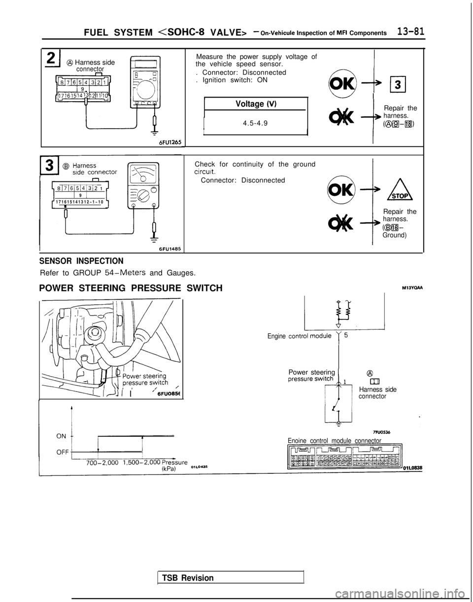
@ Harness sideconnector
6FU1265
n
8171615141312 11 9 1171615141312~1~1
0
I
Measure the power supply voltage of
the vehicle speed sensor.
. Connector: Disconnected
. Ignition switch: ON
6&loIw I
Voltage (V)
I4.5-4.9--I
Repair theharness.
II
I
Check for continuity of the ground
circuit.
Connector: Disconnected
Repair the
harness.
@WGround)
SENSOR INSPECTION
Refer to GROUP 54-Meters and Gauges.
POWER STEERING PRESSURE SWITCH MI3Yclha
------LI~lI I’ 6FUO65f
TSB Revision
Engine
Power steering 1@
blHarness sideconnector
Enoine control module connector
Page 224 of 1273
13-82 FUEL SYSTEM
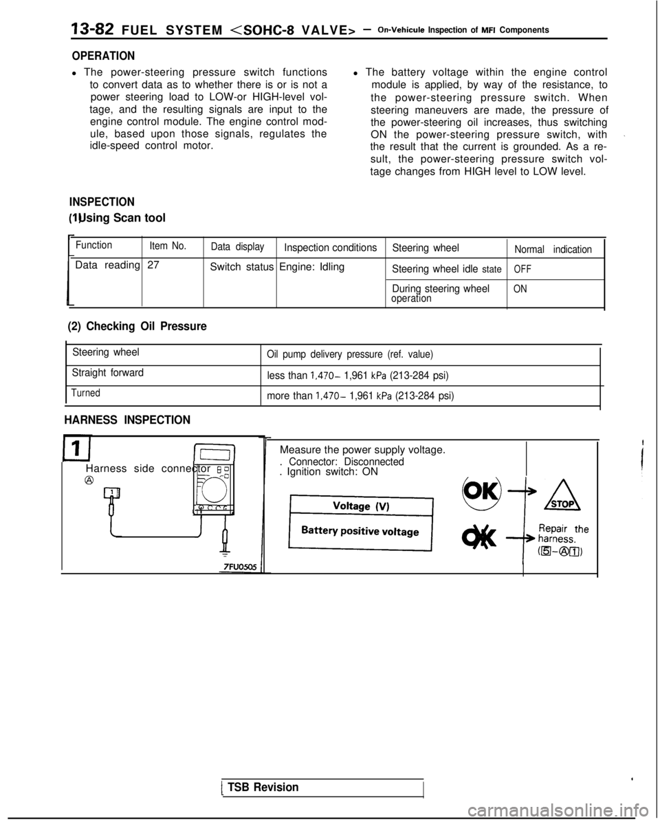
OPERATION
l The power-steering pressure switch functions
to convert data as to whether there is or is not apower steering load to LOW-or HIGH-level vol-
tage, and the resulting signals are input to the engine control module. The engine control mod-
ule, based upon those signals, regulates the
idle-speed control motor. l The battery voltage within the engine control
module is applied, by way of the resistance, to
the power-steering pressure switch. When
steering maneuvers are made, the pressure of
the power-steering oil increases, thus switching
ON the power-steering pressure switch, with
the result that the current is grounded. As a re-
sult, the power-steering pressure switch vol-
tage changes from HIGH level to LOW level.
INSPECTION I) Using Scan tool
Function
Item No.
Data reading 27
Data displayInspection conditions Steering wheelNormal indication
Switch status Engine: IdlingSteering wheel idle stateOFF
During steering wheelONoperation
(2) Checking Oil Pressure
Steering wheel
Straight forward
Turned
Oil pump delivery pressure (ref. value)
less than 1,470- 1,961 kPa (213-284 psi)
more than
1,470- 1,961 kPa (213-284 psi)
HARNESS INSPECTION
I-E-I
Harness side connector 6 0
@=- -0
Q
4 1
Measure the power supply voltage.
. Connector: Disconnected. Ignition switch: ON
[ TSB Revision
Page 225 of 1273
FUEL SYSTEM
inspection of MFI Components13-83
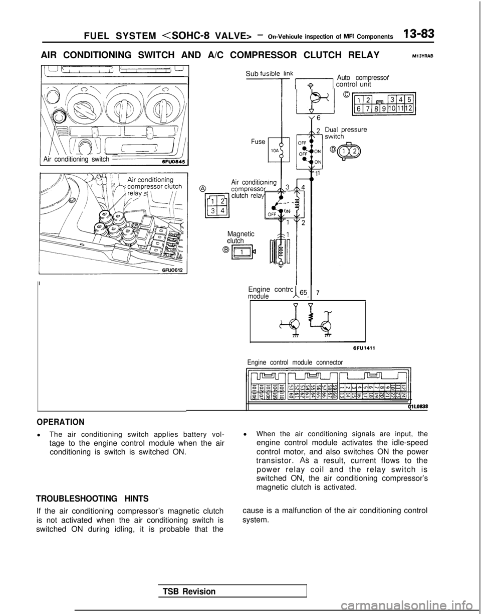
AIR CONDITIONING SWITCH AND A/C COMPRESSOR CLUTCH RELAYM13YRAE
Air conditioning switch
Sub fl
FUSC?
Air conditic@compresscclutch relal
Magnetic
clutch
Jsibie li
7
)ningIr /k
!Ik 171 control unitAuto compressor
-
-
)N
Engine control 65moduleA I7
‘1
6FU1411
Engine control module connector
IhJ-Jl r--vrJ=-Jl/l
OlLO838
OPERATION
l
The air conditioning switch applies battery vol-
tage to the engine control module when the air
conditioning is switch is switched ON.
TROUBLESHOOTING HINTS
If the air conditioning compressor’s magnetic clutch
is not activated when the air conditioning switch is
switched ON during idling, it is probable that the l
When the air conditioning signals are input, the
engine control module activates the idle-speed
control motor, and also switches ON the power
transistor.
AS a result, current flows to the
power relay coil and the relay switch is
switched ON, the air conditioning compressor’s
magnetic clutch is activated.
cause is a malfunction of the air conditioning control
system.
TSB Revision
Page 226 of 1273
13-84 FUEL SYSTEM
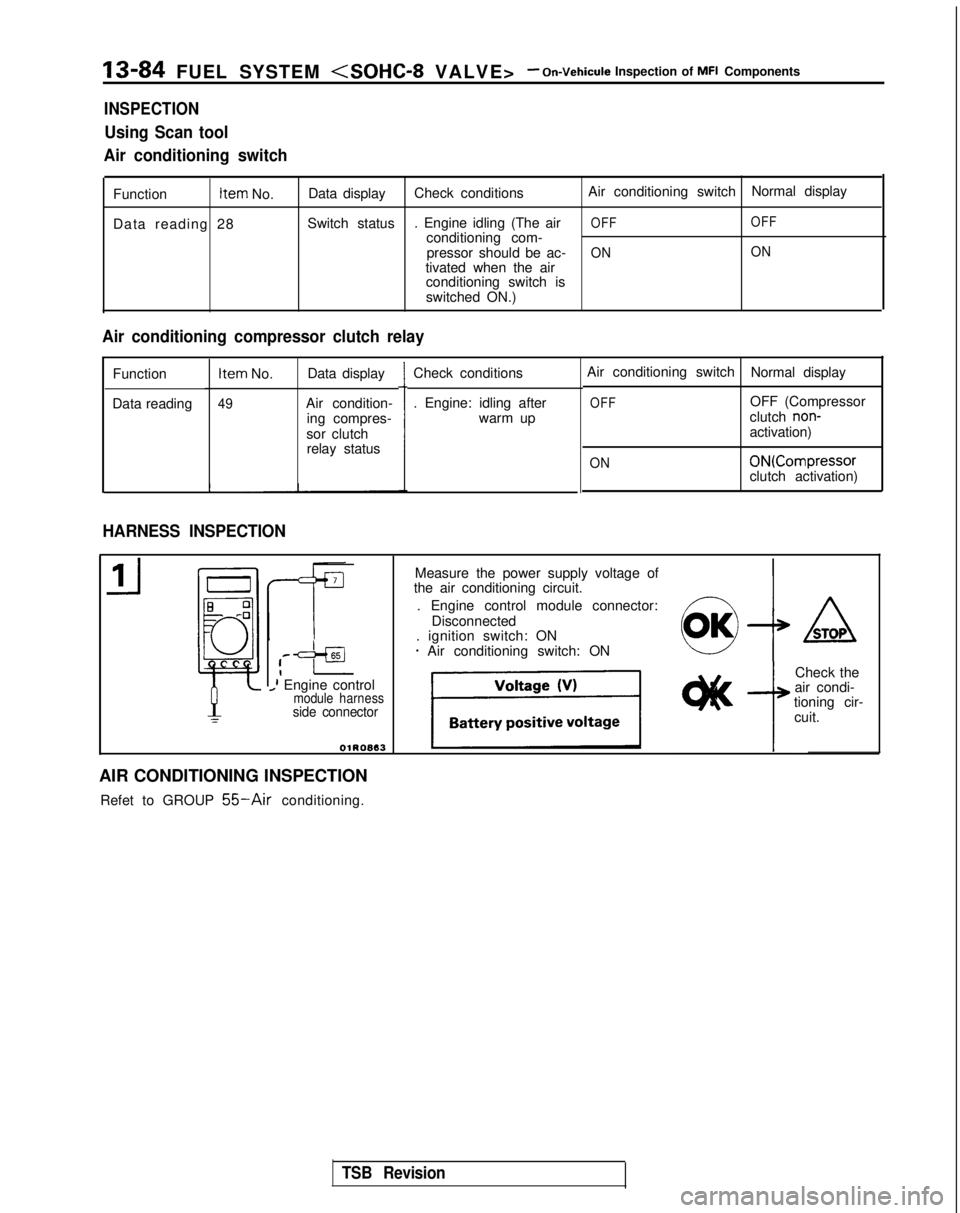
INSPECTION
Using Scan tool
Air conditioning switch
Function Item
No.
Data reading 28 Data display
Check conditions Air conditioning switch
Normal display
Switch status . Engine idling (The air
OFF OFFconditioning com-
pressor should be ac-ON ONtivated when the air
conditioning switch is
switched ON.)
Air conditioning compressor clutch relay
Function
Data reading Item
No. Data display
49Air condition-
ing compres-
sor clutch relay status Check conditions
. Engine: idling after
warm up
HARNESS INSPECTION
Air conditioning switch Normal display
OFFOFF (Compressor
clutch non-activation)
ON ON(Compressor
clutch activation)
,--=+aI_I Engine controlmodule harnessside connector
OlROB13
Measure the power supply voltage of
the air conditioning circuit.
. Engine control module connector: Disconnected
. ignition switch: ON
* Air conditioning switch: ON4
ASTOP
Check the
air condi-
tioning cir-
cuit.
AIR CONDITIONING INSPECTION Refet to GROUP
55-Air conditioning.
TSB Revision
Page 227 of 1273
FUEL SYSTEnrll (SOHC-8 VALVE> -On-Vehicule
Inspection of MFI Components13-85
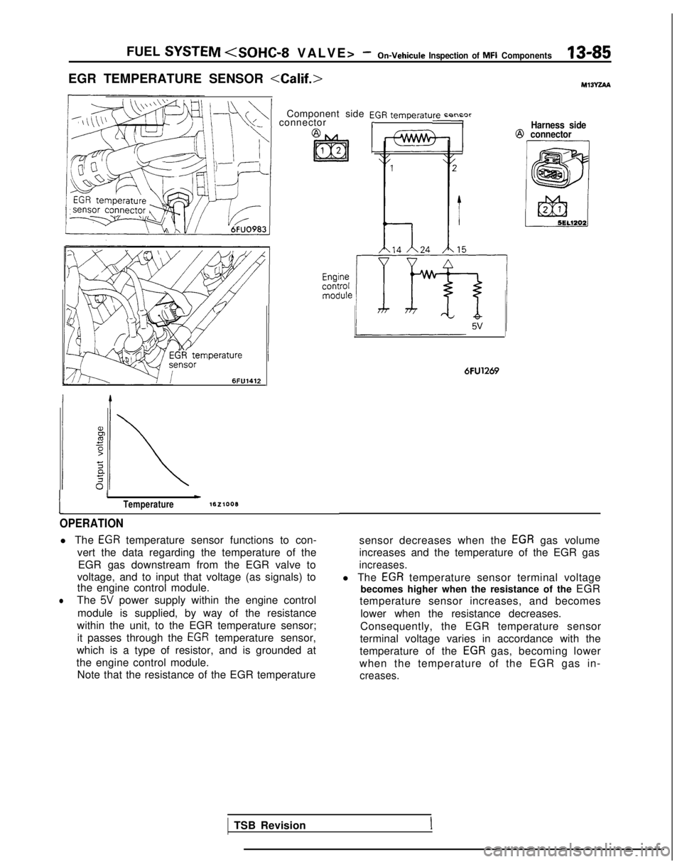
EGR TEMPERATURE SENSOR
\+\+I connectorComponent side EGR temperaturn r-n~nrrHarness side@
connector 6FlJ1412
1
IwTemperaturelEzlooB
OPERATION
l The EGR temperature sensor functions to con-
vert the data regarding the temperature of the EGR gas downstream from the EGR valve to
voltage, and to input that voltage (as signals) to
the engine control module.
lThe 5V power supply within the engine control
module is supplied, by way of the resistance
within the unit, to the EGR temperature sensor; it passes through the
EGR temperature sensor,
which is a type of resistor, and is grounded at
the engine control module. Note that the resistance of the EGR temperature
6FU1269
sensor decreases when the EGR gas volume
increases and the temperature of the EGR gas
increases.
l The EGR temperature sensor terminal voltage
becomes higher when the resistance of the EGR
temperature sensor increases, and becomes
lower when the resistance decreases.
Consequently, the EGR temperature sensor
terminal voltage varies in accordance with the
temperature of the
EGR gas, becoming lower
when the temperature of the EGR gas in-
creases.
TSB RevisionI
Page 228 of 1273
13-86 FUEL SYSTEM
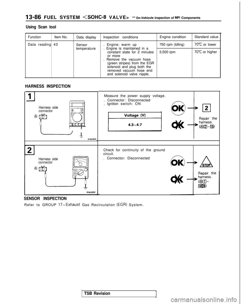
Using Scan tool
FunctionItem No.Data display Inspection conditions Engine condition
Standard value
Data reading 43 Sensor. Engine: warm up
750 rpm (Idling)
70°C or lower
temperature . Engine is maintained in a
constant state for 2 minutes 3,500 rpm
70°C or higher
or more
. Remove the vacuum hose
(green stripes) from the EGR
solenoid and plug both the removed vacuum hose end
and solenoid valve nipple.
HARNESS INSPECTION
Harness sideconnector
@qqJ
I
II
EL -:
f7
Q,
L *A’
-1I01.0523
Measure the power supply voltage.
. Connector: Disconnected
. Ignition switch: ON
Harness sideconnector
Check for continuity of the ground
circuit.
. Connector: Disconnected
SENSOR INSPECTION
Refer to GROUP 17-Exhaust Gas Recirculation (EGR)
System.
-w
STOP
TSB Revision
Page 229 of 1273
FUEL SYSTEM
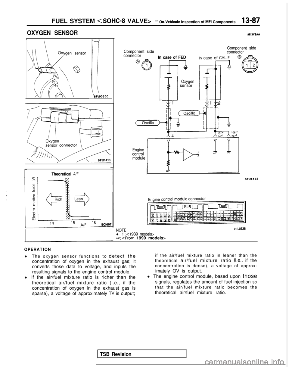
OXYGEN SENSORM13VSAa
/
Oxygen sensor
)G/’ ‘;‘@
i b\A
-
I6FUO659
Theoretical A/F
Component side
Component sideconnectorconnectorIn case of FEDIn case of CALIFI r
Oxygensensor
i klJ
I
-
11 2
Enginecontrol
module
6FU1452
NOTE01 Lo836
l 1 :
OPERATION
l The oxygen sensor functions to
detect th
e
concentration of oxygen in the exhaust gas; it
converts those data to voltage, and inputs the
resulting signals to the engine control module.
l If the air/fuel mixture ratio is richer than the
theoretical air/fuel mixture ratio (i.e., if theconcentration of oxygen in the exhaust gas issparse), a voltage of approximately
1V is output; if the air/fuel mixture ratio in leaner than the
theoretical air/fuel mixture ratio
(Le., if the
concentration is dense), a voltage of approx-
imately OV is output.
l The engine control module, based upon those
signals, regulates the amount of fuel injection SO
that the air/fuel mixture ratio becomes th
e
theoretical air/fuel mixture ratio.
TSB Revision
Page 230 of 1273
13-88 FUEL SYSTEM
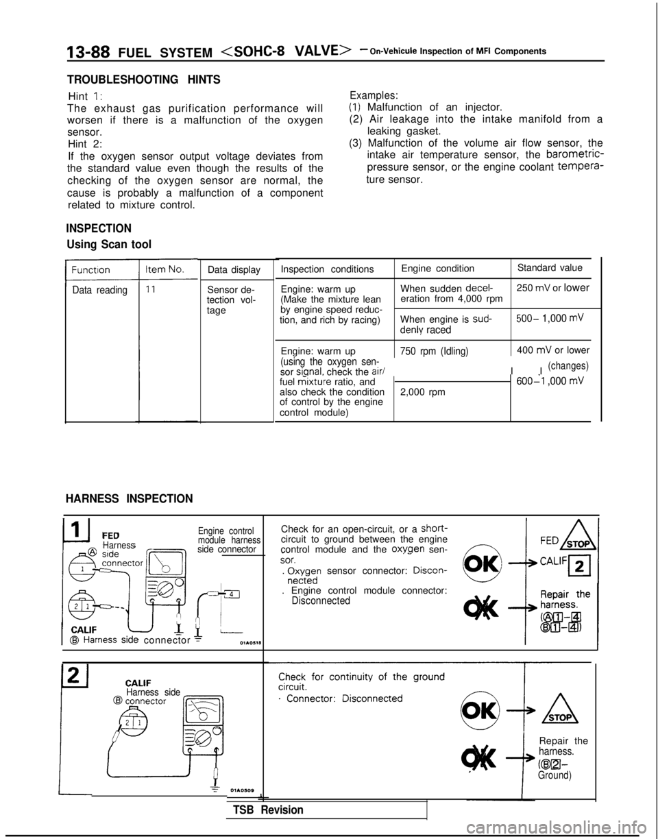
TROUBLESHOOTING HINTS
Hint I’
The exhaust gas purification performance will
Examples:
(1) Malfunction of an injector.
worsen if there is a malfunction of the oxygen sensor. Hint 2:
If the oxygen sensor output voltage deviates from
the standard value even though the results of the
checking of the oxygen sensor are normal, the
cause is probably a malfunction of a component related to mixture control. (2) Air leakage into the intake manifold from a
leaking gasket.
(3) Malfunction of the volume air flow sensor, the intake air temperature sensor, the barometric-
pressure sensor, or the engine coolant tempera-
ture sensor.
Data reading
INSPECTION
Using Scan tool
HARNESS INSPECTION
Data display
Sensor de-
tection vol-
tage Inspection conditions
Engine conditionStandard value
Engine: warm up When sudden decel-
250
mV or lower
(Make the mixture lean eration from 4,000 rpm
by engine speed reduc-
tion, and rich by racing) When engine is sud-
500- 1,000 mV
denly raced
Engine: warm up750 rpm (Idling)
(using the oxygen sen-
sor sianal.
check the air/
400
mV or lower
I I
(changes)
fuel mixture ratio, and600-l ,000 mValso check the condition 2,000 rpm
of control by the engine
control module)
I CALIF@I Hal
FEDHarness
ness
side
connector
Engine control
module harness
side connector
Check for an open-circuit, or a short-circuit to ground between the engine
control module and the oxwen sen-f7 _-
~~SOT.‘-. r$;rdn sensor connector: Drscon-
. Engine control module connector:Disconnected CALIF
Harness side
Check for continuity of the ground
.“‘..“...;;”
Repair theharness.
KEEI-Ground)
1
TSB Revision