MITSUBISHI GALANT 1989 Service Repair Manual
Manufacturer: MITSUBISHI, Model Year: 1989, Model line: GALANT, Model: MITSUBISHI GALANT 1989Pages: 1273, PDF Size: 37.62 MB
Page 781 of 1273
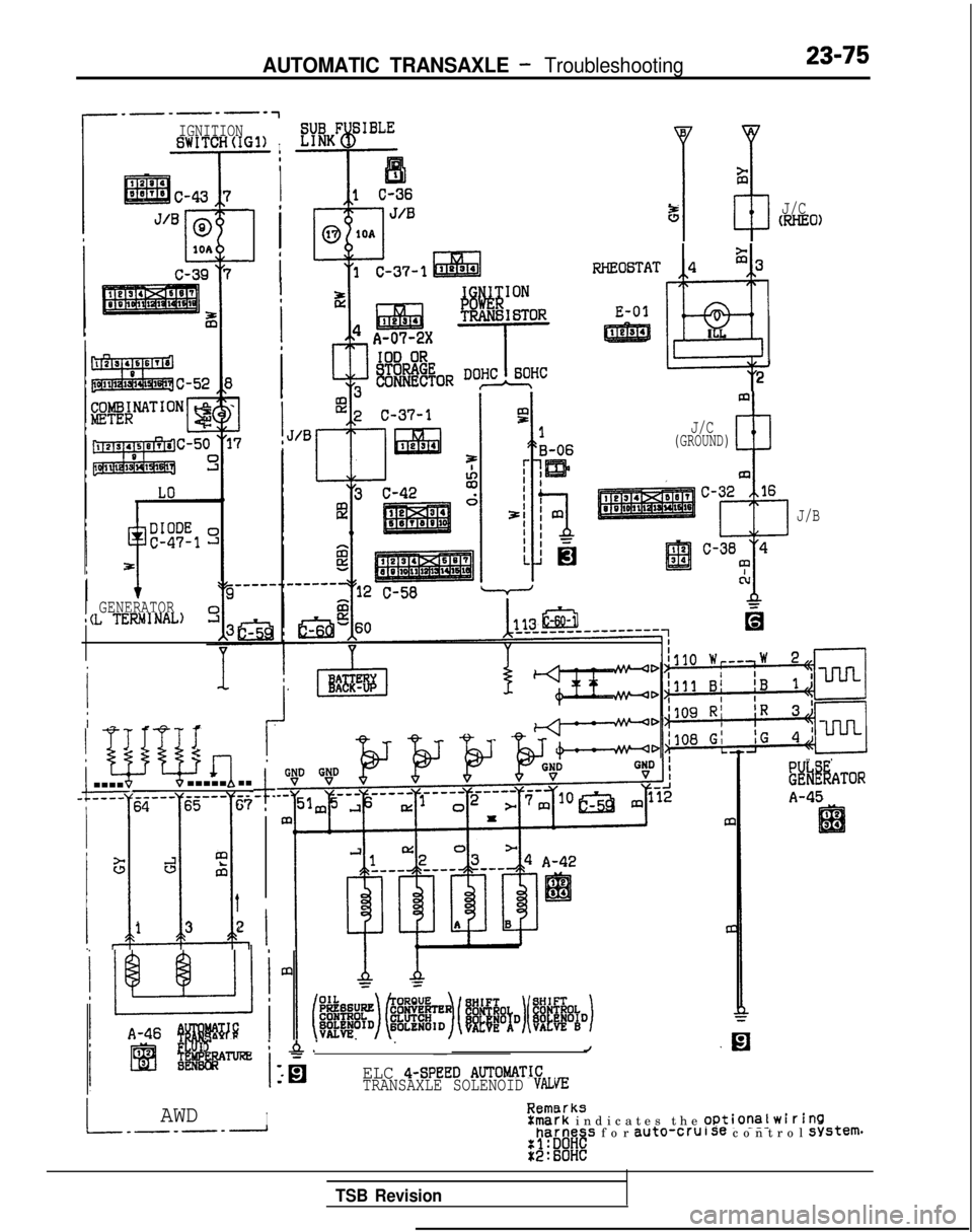
AUTOMATIC TRANSAXLE - Troubleshooting23-75
IGNITIONBWITCH(IG1)I
Ia
I
1 ’
iRHEO6TAT
E-01
5J/CmHE0)
GENERATORl(L TERMNAL)
4$3
@
I
L
2
I I-?i
wb&q-------.-.-.-------6567
I
Y
.l!.
GJal
t
13 2
$- .
I
J/C(GROUND)
J/B
s -iA.’ . .
~J
ELC 4-SPEED AUTOtdATICTRANSAXLE SOLENOID VALVIZ
8rksIAWDIE::-...-rk indicates the Optional WirinQharness for auto-cruise control system.
..a
.nnuL_-_-____1
8ki%ATOR
A-45
TSB Revision
Page 782 of 1273
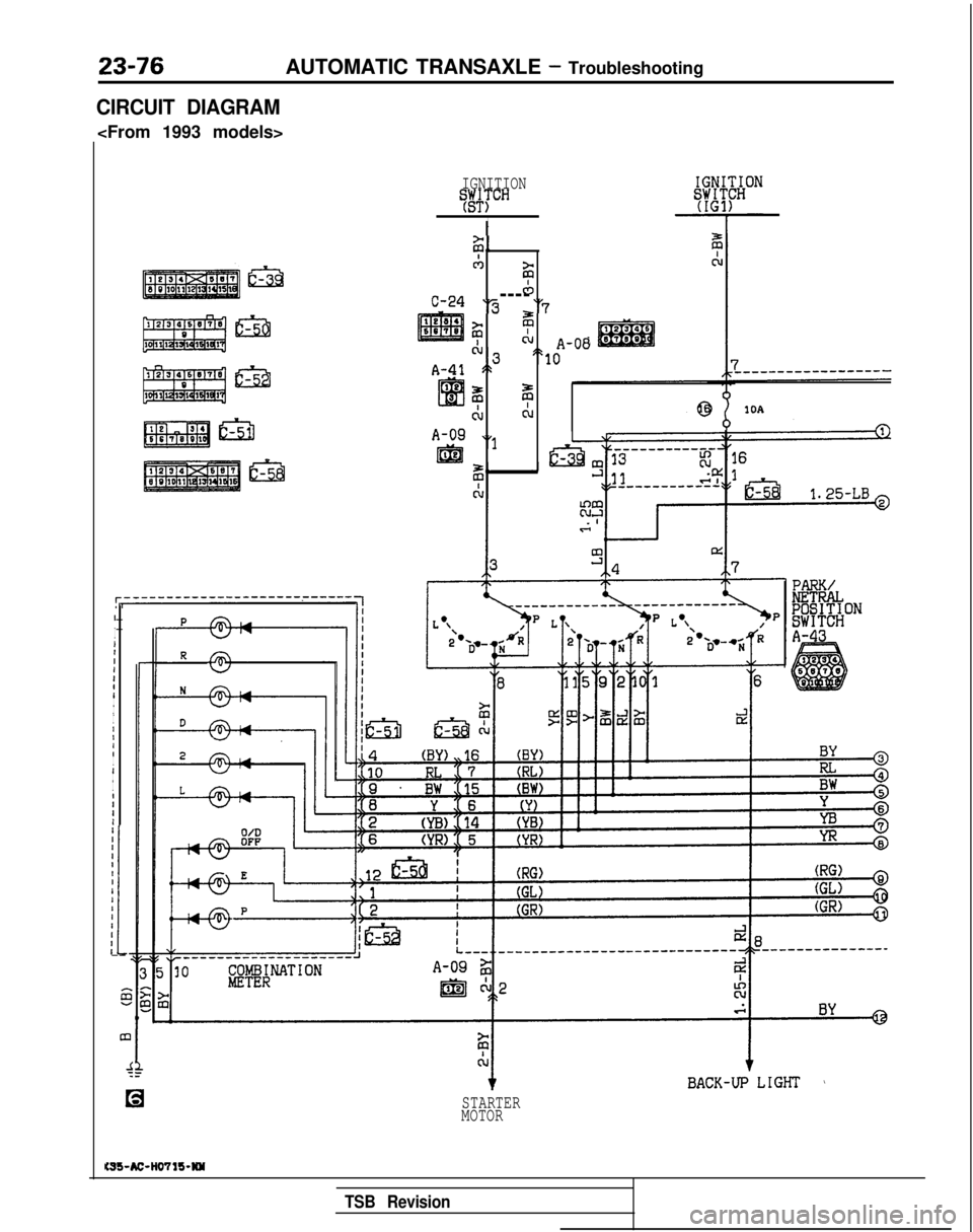
23-76AUTOMATIC TRANSAXLE - Troubleshooting
CIRCUIT DIAGRAM
IGNITIONT#TCH
I
IIIIIII
II
I
I
I
IIII
I
I
I
I
IIII
I
iII-- 5
m
4
C-24
A-41
A-09
I&
ii,,
CAzicb----‘3 “7
? zcl,\ A-08",e "10,.
z z
CL
&
“1
Gl)
I
10A
STARTER
MOTOR
PARK/
lg@&bN
A-43
KSS-AC-H0711-W
TSB Revision
Page 783 of 1273
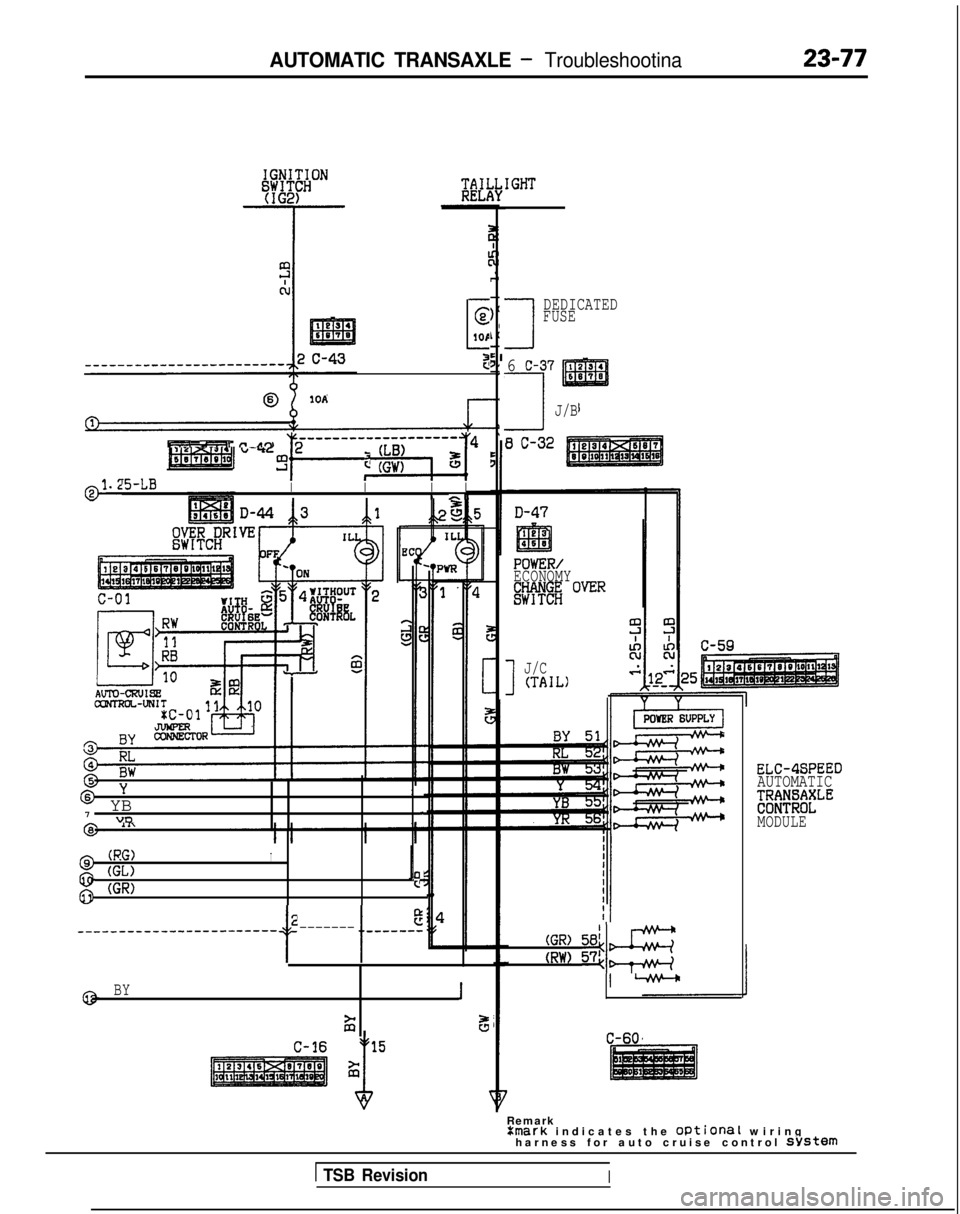
AUTOMATIC TRANSAXLE - Troubleshootina
-
E
1OP
3
@IOA
PT.-. L-_..il Tr-ltn
-
.-
-~-------y~-J4 ~
!kJ-LBII
I II rrl
6Y
* YB
I
7"DI.
(RG)
@ (GL)I
g (GR)Is
2
t I
e_-_-_----_~~__---~~~~~~~ -------w-v----
BY
1 2
s
1
DEDICATED
FUSE
6 C-37
7J/B
8 C-32
POWER/
ECONOMY
!RRi OVER
1
J/C(TAIL)
ELC-4SPEED
AUTOMATIC
;;;f?;;lfLE
MODULE
(GR) 58;&
(RW) 574~
C-60
Remark Xmark
indicates the Optional wirin
g
harness for auto cruise control
system
1 TSB RevisionI
Page 784 of 1273
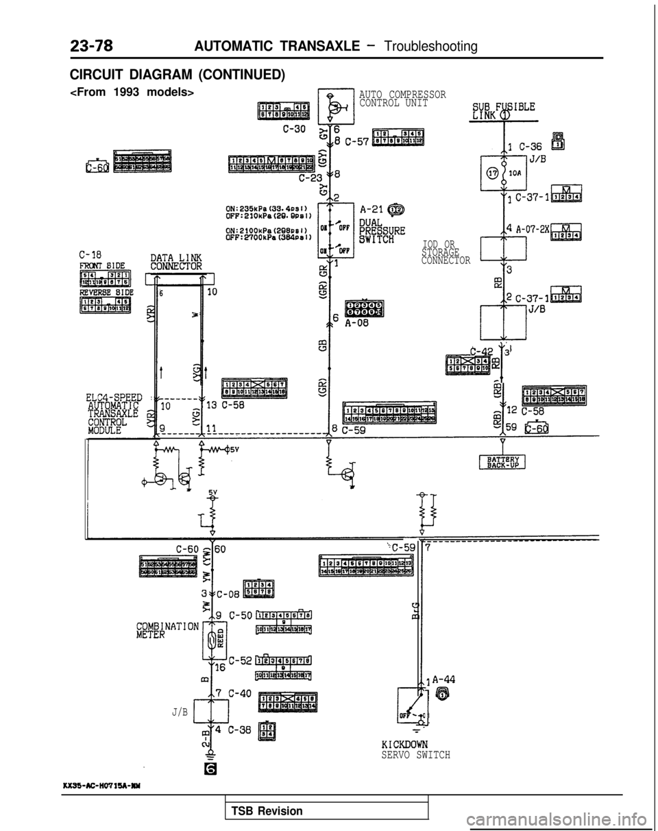
AUTOMATIC TRANSAXLE - Troubleshooting
CIRCUIT DIAGRAM (CONTINUED)
El
AUTO COMPRESSORCONTROL UNIT
C-18
ELC4-SPEED :
6
5
J/B IOD OR
STORAGE
CONNECTOR
T
C-42 3
@
I
A-44
'63
1
KICKDOWN
SERVO SWITCH
1(x95-AC-IlWlU-NW
TSB Revision
Page 785 of 1273
AUTOMATIC TRANSAXLE - Troubleshooting23-79
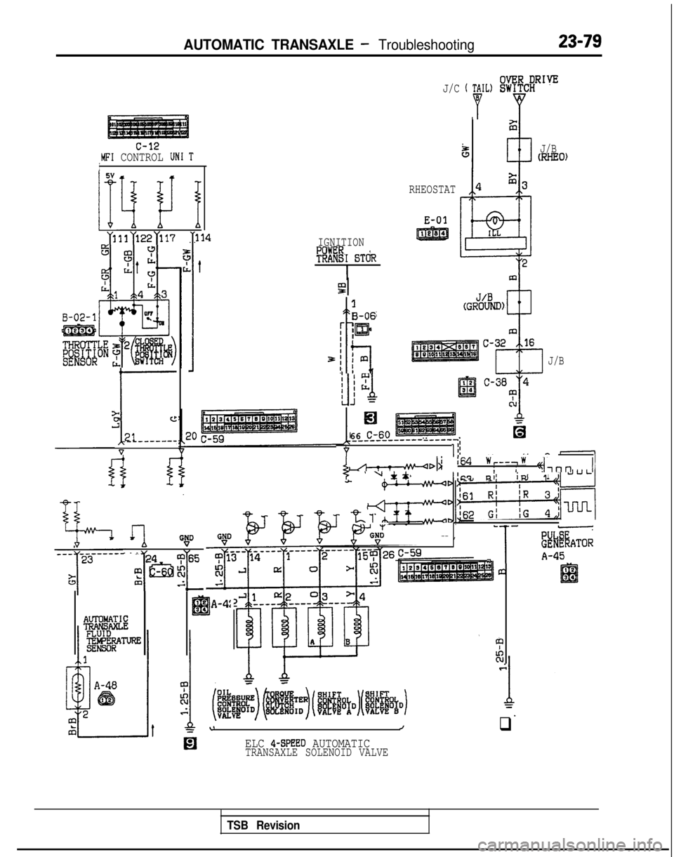
c-12MFI CONTROL UN1 TI5V
IFI I! I
m~131>22~117. .
I-
a
J”c
;It------
V
IGNITION
?!RE-I BT&
I
1
B-06
[ lm
3;
t7 fmI! 1
J/C ’ P’L)!%flg
5J/BWIEO)
RHEOSTAT
E-01
J/B
1.
El
66 C-60_____-_-m-w---v-v-
Yli
I-~I~i64w,--,w i!
’ u Jtt; i 4-l”” II!C? niiR1
.rllG!D
--
-
m2&jg”5
7 L&.z
’ eIEB34A-4:
twT&AAg
rGN:-- --- ,
- -
V
,,,1
-
ii#d%ATOR
A-45._I2IEil34
43
tc
\Jq
ELC 4-SPEED AUTOMATICTRANSAXLE SOLENOID VALVE
TSB Revision
Page 786 of 1273
23-80AUTOMATIC TRANSAXLE - Troubleshooting
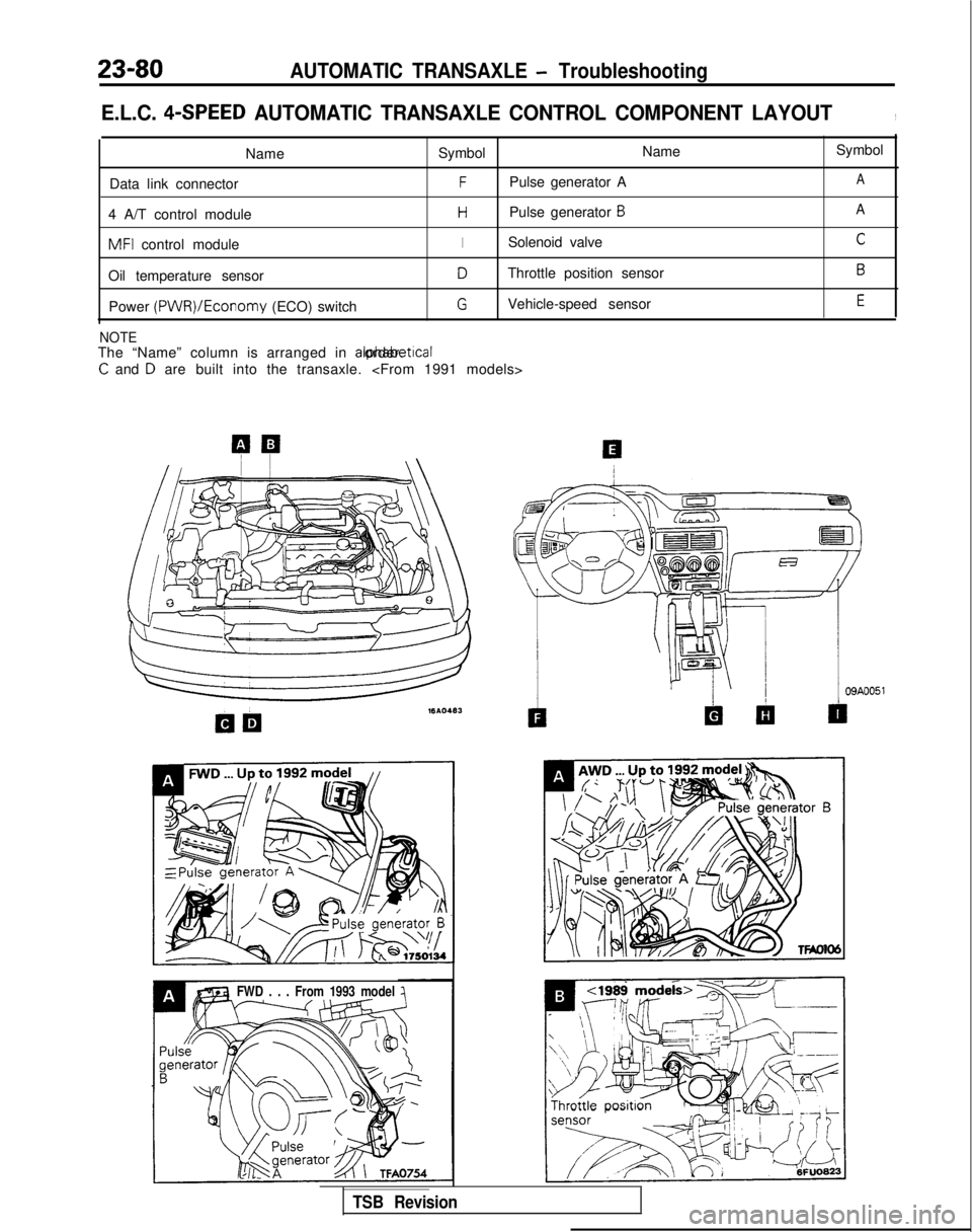
E.L.C. 4-SPEED AUTOMATIC TRANSAXLE CONTROL COMPONENT LAYOUT,
NameSymbol Name
Data link connector
FPulse generator A
4 A/T control module
HPulse generator 6
MFI control moduleISolenoid valve
Oil temperature sensor
DThrottle position sensor
Power (PWR)/Economy
(ECO) switch
GVehicle-speed sensor
NOTEThe “Name” column is arranged in alphabetrcal order.
C and D are built into the transaxle.
Symbol
A
A
C
B
E
FWD . . . From 1993 model
TSB Revision
Page 787 of 1273
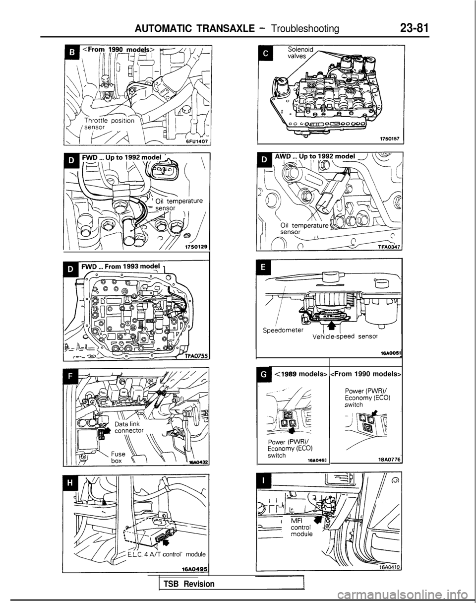
AUTOMATIC TRANSAXLE - Troubleshooting23-81
control module
Vet-kle-sbeed sensor
16AOOSl4
<1989 models>
Power
(PWR)/Economy (ECO)switch 16AO463
Power (PWR)/Economy (ECO)switch
WA0776
TSB Revision
Page 788 of 1273
23-82AUTOMATIC TRANSAXLE - Service Adjustment Procedures
HOTTFA0715
AWD
LT FA0700J
SERVICE ADJUSTMENT PROCEDUR&g
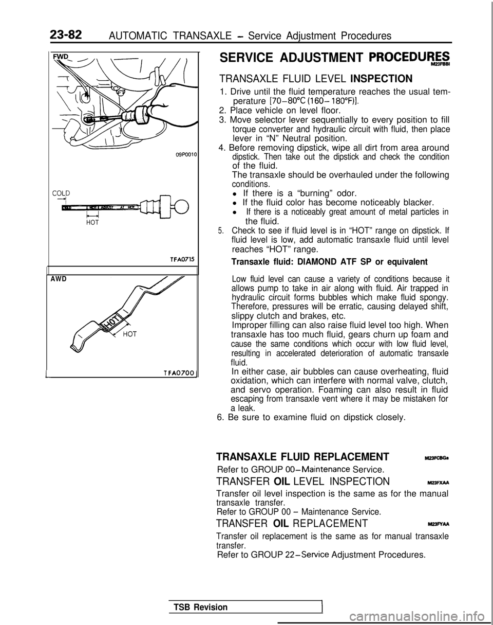
TRANSAXLE FLUID LEVEL INSPECTION
1. Drive until the fluid temperature reaches the usual tem-
perature [70-80°C
(160- 18O”F)I.
2. Place vehicle on level floor.
3. Move selector lever sequentially to every position to fill
torque converter and hydraulic circuit with fluid, then place
lever in “N” Neutral position.
4. Before removing dipstick, wipe all dirt from area around
dipstick. Then take out the dipstick and check the condition
of the fluid.
The transaxle should be overhauled under the following
conditions.
l If there is a “burning” odor.
l If the fluid color has become noticeably blacker.
l
If there is a noticeably great amount of metal particles in
the fluid.
5.Check to see if fluid level is in “HOT” range on dipstick. If
fluid level is low, add automatic transaxle fluid until level
reaches “HOT” range.
Transaxle fluid: DIAMOND ATF SP or equivalent
Low fluid level can cause a variety of conditions because it
allows pump to take in air along with fluid. Air trapped in hydraulic circuit forms bubbles which make fluid spongy.
Therefore, pressures will be erratic, causing delayed shift,
slippy clutch and brakes, etc.
Improper filling can also raise fluid level too high. When
transaxle has too much fluid, gears churn up foam and
cause the same conditions which occur with low fluid level, resulting in accelerated deterioration of automatic transaxle
fluid.
In either case, air bubbles can cause overheating, fluid
oxidation, which can interfere with normal valve, clutch,
and servo operation. Foaming can also result in fluid
escaping from transaxle vent where it may be mistaken for
a leak.
6. Be sure to examine fluid on dipstick closely.
TRANSAXLE FLUID REPLACEMENTM23FcsGa
Refer to GROUP 00-Maintenance
Service.
TRANSFER OIL LEVEL INSPECTIONMm=xM
Transfer oil level inspection is the same as for the manual
transaxle transfer.
Refer to GROUP 00
- Maintenance Service.
TRANSFER OIL REPLACEMENTM23FYAA
Transfer oil replacement is the same as for manual transaxle
transfer.
Refer to GROUP 22-Service
Adjustment Procedures.
TSB Revision
Page 789 of 1273
AUTOMATIC TRANSAXLE - Service Adjustment Procedures23-83
I:
I’
4989 models>
09A0140
6% Button pressed (while brakepedal is depressed)
c Button not pressed
0 Button pressed
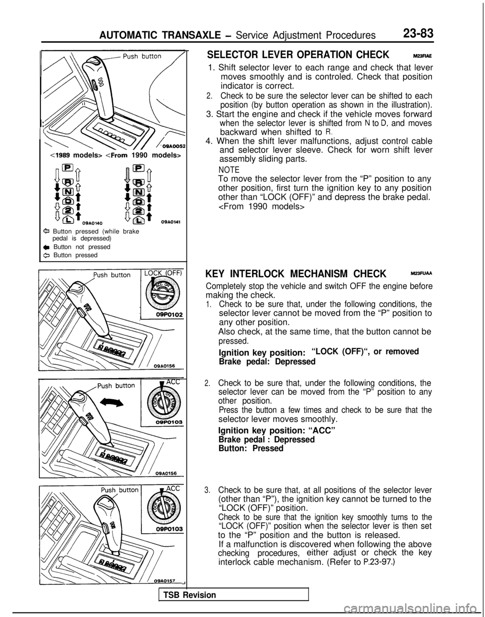
SELECTOR LEVER OPERATION CHECKM23flAE
1. Shift selector lever to each range and check that lever
moves smoothly and is controled. Check that position
indicator is correct.
2.Check to be sure the selector lever can be shifted to each
position (by button operation as shown in the illustration).
3. Start the engine and check if the vehicle moves forward
when the selector lever is shifted from N to D, and moves
backward when shifted to R.
4. When the shift lever malfunctions, adjust control cable and selector lever sleeve. Check for worn shift lever
assembly sliding parts.
NOTE
To move the selector lever from the “P” position to any
other position, first turn the ignition key to any position
other than “LOCK (OFF)” and depress the brake pedal.
KEY INTERLOCK MECHANISM CHECKM23FUAA
Completely stop the vehicle and switch OFF the engine before
making the check.
1.Check to be sure that, under the following conditions, the
selector lever cannot be moved from the “P” position to
any other position.
Also check, at the same time, that the button cannot be
pressed.
Ignition key position:“LOCK (OFF)“, or removed
Brake pedal: Depressed
2.Check to be sure that, under the following conditions, the selector lever can be moved from the “P” position to any
other position.
Press the button a few times and check to be sure that the
selector lever moves smoothly.
Ignition key position: “ACC”
Brake pedal : Depressed
Button: Pressed
3.Check to be sure that, at all positions of the selector lever
(other than “P”), the ignition key cannot be turned to the
“LOCK (OFF)” position.
Check to be sure that the ignition key smoothly turns to the
“LOCK (OFF)” position when the selector lever is then set
to the “P” position and the button is released.
If a malfunction is discovered when following the above
checking procedures,either adjust or check the key
interlock cable mechanism. (Refer to
P.23-97.)
-I
TSB Revision
Page 790 of 1273
23-84AUTOMATIC TRANSAXLE - Service Adiustment Procedures
Brake
pedal
IOSM0045
A
iection A-A
Switch body
- 175133
12 mm (.47 in.)
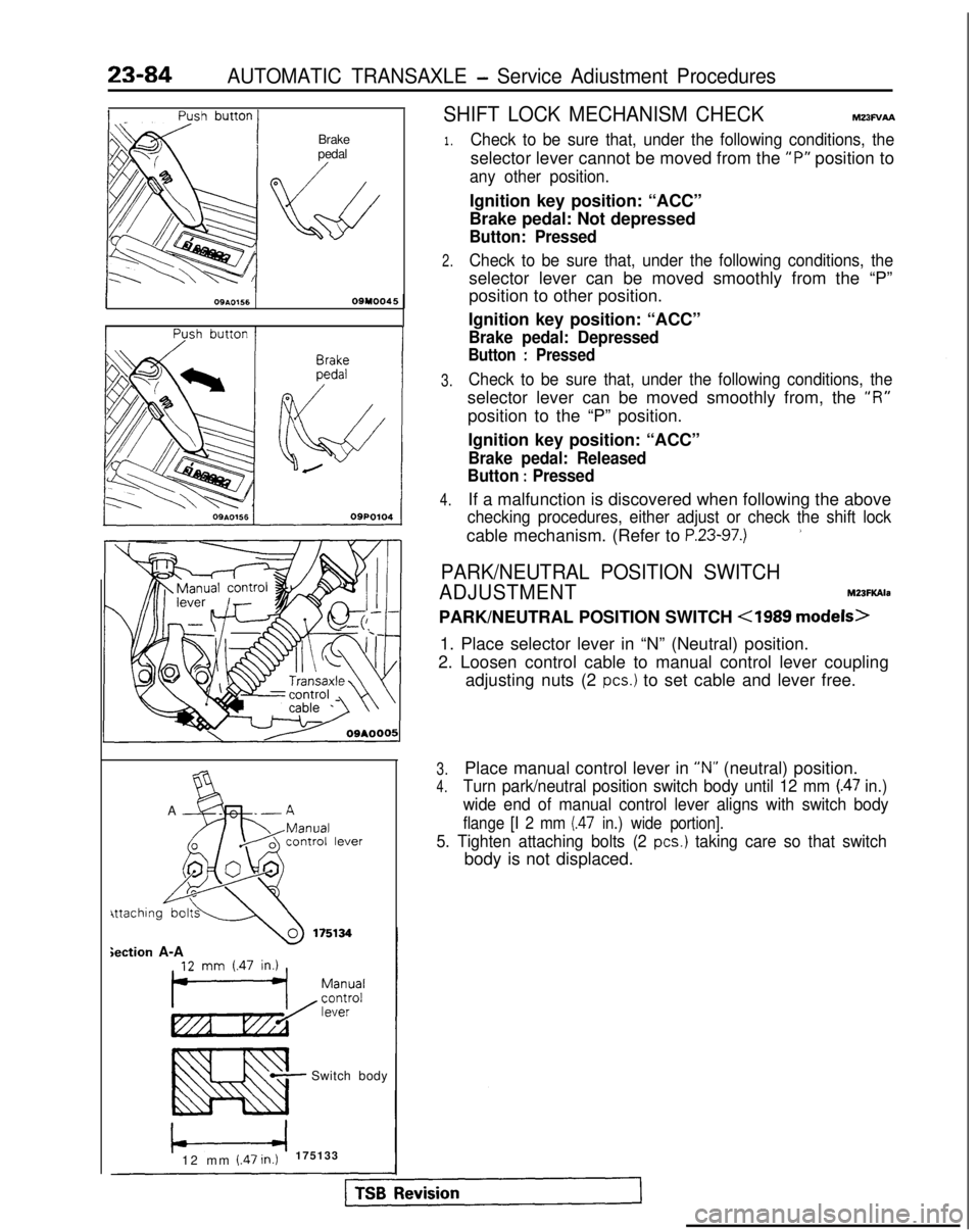
SHIFT LOCK MECHANISM CHECKMz3Fv~
1.
2.
3.
4.
Check to be sure that, under the following conditions, the
selector lever cannot be moved from the “P”
position to
any other position.
Ignition key position: “ACC”
Brake pedal: Not depressed
Button: Pressed
Check to be sure that, under the following conditions, the
selector lever can be moved smoothly from the “P”
position to other position.
Ignition key position: “ACC”
Brake pedal: Depressed
Button : Pressed
Check to be sure that, under the following conditions, the
selector lever can be moved smoothly from, the “I?”
position to the “P” position.
Ignition key position: “ACC”
Brake pedal: Released
Button
: Pressed
If a malfunction is discovered when following the above
checking procedures, either adjust or check the shift lock
cable mechanism. (Refer to P.23-97.)’
PARK/NEUTRAL POSITION SWITCH
ADJUSTMENT M23FKAla
PARK/NEUTRAL POSITION SWITCH
<1989 models>
1. Place selector lever in “N” (Neutral) position.
2. Loosen control cable to manual control lever coupling adjusting nuts (2
PCS.) to set cable and lever free.
3.Place manual control lever in “N” (neutral) position.
4.Turn park/neutral position switch body until 12 mm (.47 in.)
wide end of manual control lever aligns with switch body
flange [I 2 mm (.47 in.) wide portion].
5. Tighten attaching bolts (2 PCS.) taking care so that switch
body is not displaced.