MITSUBISHI GALANT 1989 Service Repair Manual
Manufacturer: MITSUBISHI, Model Year: 1989, Model line: GALANT, Model: MITSUBISHI GALANT 1989Pages: 1273, PDF Size: 37.62 MB
Page 751 of 1273
AlJTCMVlATlC TRANSAXLE - Troubleshooting23-45
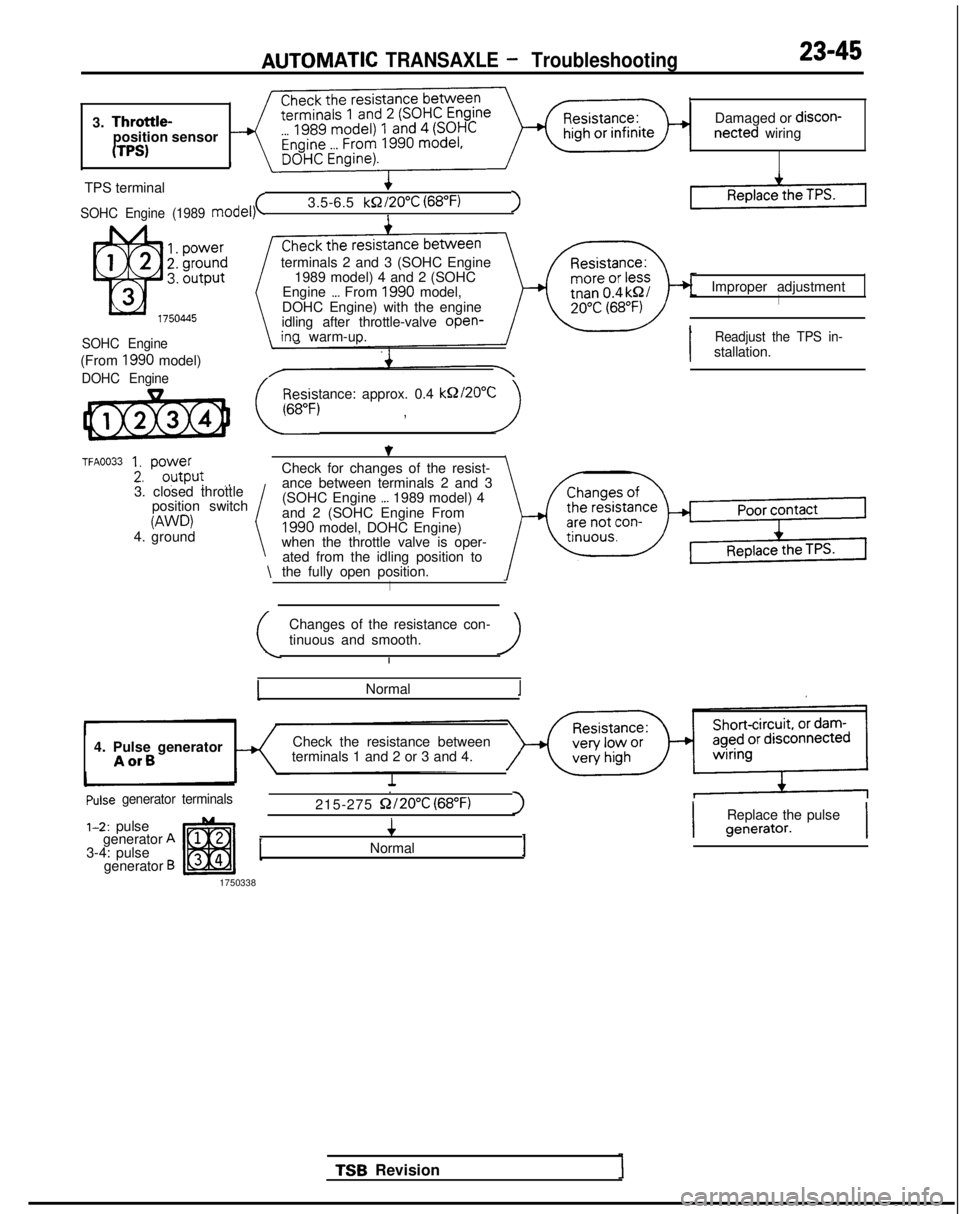
3. Throttle-position sensor
UPS)
Damaged or discon-netted wiring
TPS terminal
SOHC Engine (1989 model)(3.5-6.5 kQ/20”C
(68°F)1I
SOHC Engine
(From 1990 model)
DOHC Engine
TFA0033 1. power
2. outpur.,
terminals 2 and 3 (SOHC Engine
1989 model) 4 and 2 (SOHC
Engine
_._ From 1990 model,
DOHC Engine) with the engine
idling after throttle-valve open-
ina warm-up.
Resistance: approx. 0.4
kQZ20”C
(,6,, , )
3. closed throttle position switch
W’D)4. ground \
Check for changes of the resist-
ance between terminals 2 and 3
(SOHC Engine
,._ 1989 model) 4
and 2 (SOHC Engine From
1990 model, DOHC Engine)
when the throttle valve is oper-
ated from the idling position to
the fully open position.
I
Changes of the resistance con-
tinuous and smooth.
Normal
4. Pulse generator
AorB
Check the resistance between
terminals 1 and 2 or 3 and 4.
Pulse generator terminals.
215-275
Q/20% (68°F)I
1-2: pulse
generator A3-4: pulse
generator B
4
Normal1
1750338 Improper adjustment
I
I
Readjust the TPS in-stallation.
TSB Revision
I
Replace the pulsegenerator.I
Page 752 of 1273
23-46AUTOMATIC TRANSAXLE - Troubleshootincl
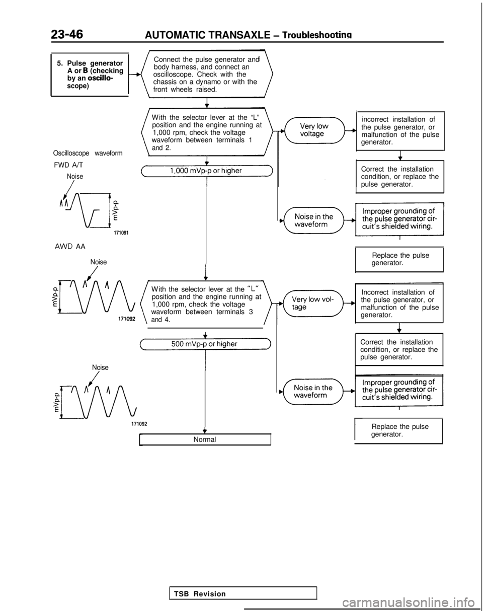
5. Pulse generatorA or B (checking
by an oscillo-
scope)K
Connect the pulse generator and
body harness, and connect an
oscilloscope. Check with the
chassis on a dynamo or with the
front wheels raised.
Oscilloscope waveform
FWD
/VT
Noise
/Ah --L
Ar
IP
-iE
171091 AWD
AA
Noise
W
ith the selector lever at the “L”
position and the engine running at
1,000 rpm, check the voltage
waveform between terminals 1
and 2.
1
W
ith the selector lever at the
“L”position and the engine running at
1,000 rpm, check the voltage
waveform between terminals 3
and 4.
Noise
A
(6
171092+
Normal incorrect installation of
the pulse generator, or malfunction of the pulse
generator. 4
Correct the installation
condition, or replace the
pulse generator.
Replace the pulse
generator.
Incorrect installation of
the pulse generator, or
malfunction of the pulse
generator. 4
Correct the installation
condition, or replace the
pulse generator.r
Replace the pulse
generator.
TSB Revision
Page 753 of 1273
AUTOMATIC TRANSAXLE - Troubleshooting23-47
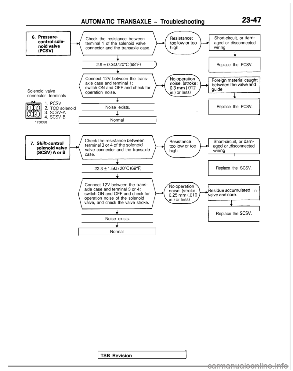
Check the resistance betweenShort-circuit, or dam-
terminal 1 of the solenoid valve aged or disconnected
connector and the transaxle case. wiring4 4
2.9
+ 0.3Q/20°C (68°F)1Replace the PCSV.
t
Solenoid valve
connector terminals
PCSVTCC solenoid
;g;:;
Connect 12V between the trans-
axle case and terminal 1;
switch ON and OFF and check for
operation noise.
1
Noise exists. 1Replace the PCSV.1J
NormalI
valve connector and the transaxleAlShort-circuit, or
dam-aoed or disconnected-=!-- -’ -.
wrringI
I
f
22.3 k l.5Q/20°C (68°F)Replace the SCSV.
4II,1 I \
Connect
12V between the trans-
axle case and terminal 3 or 4; switch ON and OFF and check for
operation noise of the solenoid
valve, and check the valve stroke.
TSB Revision
yF$$;za;:pulated in /
+
Noise exists. 4
Normal
1Replace the SCSV.]
Page 754 of 1273
23-48AUTOMATIC TRANSAXLE
- Troubleshooting
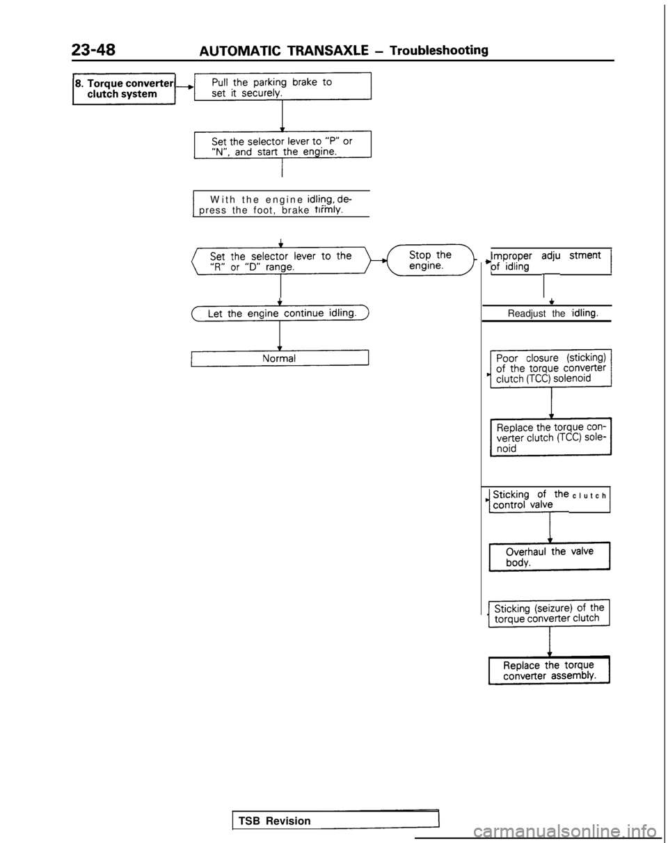
1 press the foot, brake firmly.1W
ith the engine
idliqg, de-
Let the engine continue idling.
3
TSB Revision
4;ry;pn”g’ y stment 1
+
Readjust the ,idling.
1 ~i$.;h~,~~~e clutch 1
Page 755 of 1273
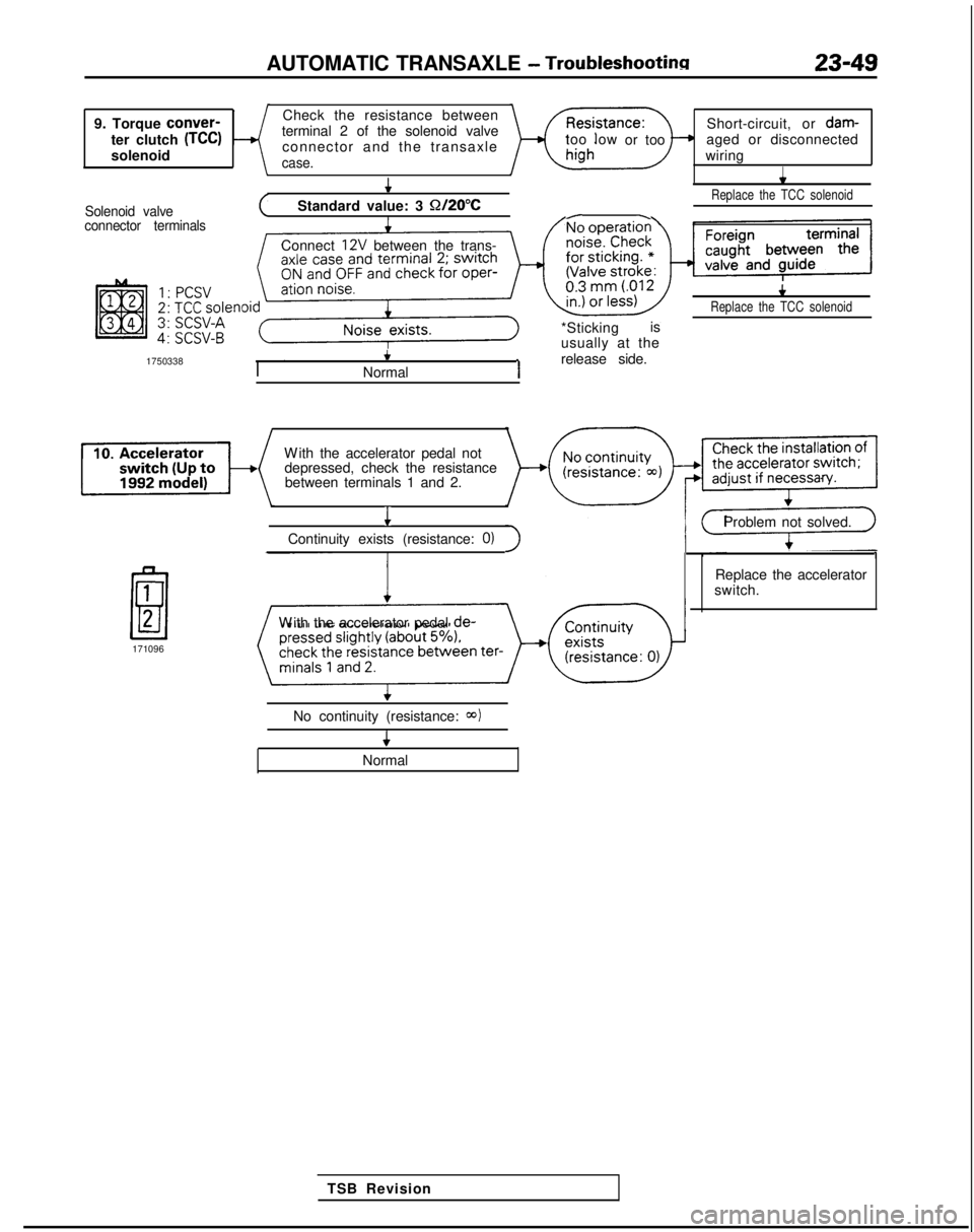
AUTOMATIC TRANSAXLE - Troubleshootinn
9. Torque
conver-
ter clutch
(TCC)solenoid Check the resistance between
terminal 2 of the solenoid valve connector and the transaxlecase.
Short-circuit, or dam-
too low
or too aged or disconnected
wiring
I
Solenoid valve
4*
(Standard value: 3 Q/2O”CReplace the TCC solenoid
/-connector terminals
Connect 12V between the trans-
*Stickingis
usually at the
1750338
4
Normal1release side.
4
Replace the TCC solenoid
W
ith the accelerator pedal not
depressed, check the resistance between terminals 1 and 2.
1
Continuity exists (resistance: 0)
Problem not solved.
1
1
E/l2
171096 Replace the accelerator
switch.
W
ith the accelerator pedal de-
No continuity (resistance:
CQ)I
TSB Revision
+
Normal
Page 756 of 1273
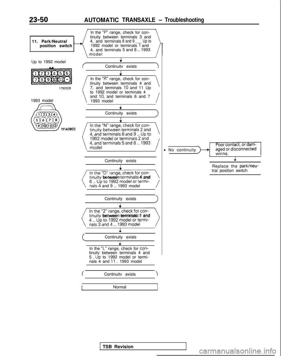
23-50AUTOMATICTRANSAXLE-Troubleshooting
11. Park/Neutralposition switch In the “P”
range, check for con-
tinuity between terminals 3 and
4, and terminals8 and 9 ___ Up to1992 model or terminals 1 and
4, and terminals 5 and 8 _._ 1993
Up to 1992 model
1993 model
‘FA0802
\ mode
l
\I
4
cContinuitv exists-I
In the
“R”
range, check for con-
tinuity between terminals 4 and 7, and terminals
10 and 11 Up\
to 1992 model or terminals 4and IO, and terminals 6 and 7
1993 model
I
+
Continuity exists>I
tinuity between’terminals 2 and
~~
Continuity existsI
iv- trnurty
between termrnals
4 and
\nals4 and 9 __. 1993 model/
Continuity existsI
(() trnurty
between terminals 1 and
(Continuity exists
In the
“L” range, check for con-
tinuitv between terminals 4 and
5 .
Up to 1992 model or termi-
nals 4 and 11 . 1993 model
(Continuitv exists
Normal
F No continuity-)+I1
,1
Replace the park/neu- tral
position switch.
TSB Revision
Page 757 of 1273
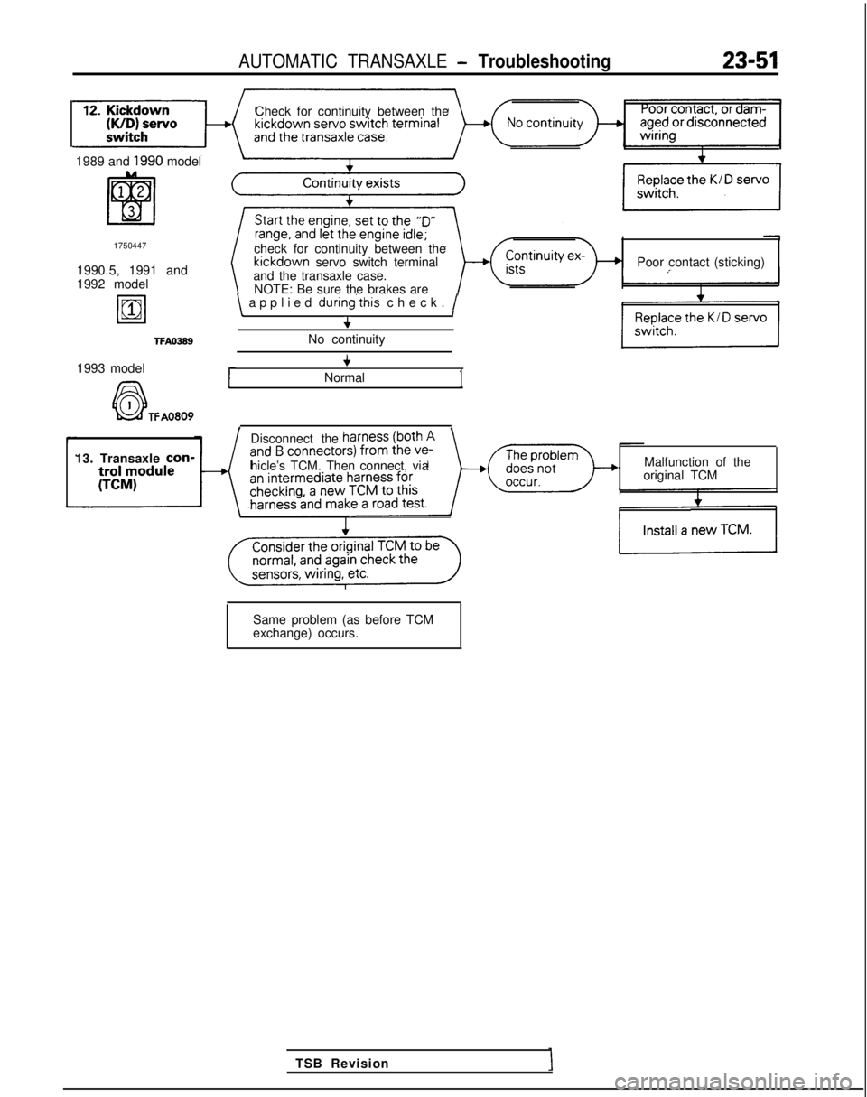
AUTOMATIC TRANSAXLE - Troubleshooting23-51
Check for continuity between the
1989 and
1990 model
1750447
1990.5, 1991 and
1992 model
19811
TFAO389
check for continuity between the kickdown
servo switch terminal
and the transaxle case. Poor contact (sticking)
NOTE: Be sure the brakes are
\ applied during’this
check. /\I+
No continuity
1993 model
A6-l
+
Normal1
k&f TFA0809, ,
Disconnect the
13. Transaxle con-
hicle’s TCM. Then connect, via Malfunction of the
original TCM
TSB Revision
Same problem (as before TCM
exchange) occurs.
Page 758 of 1273
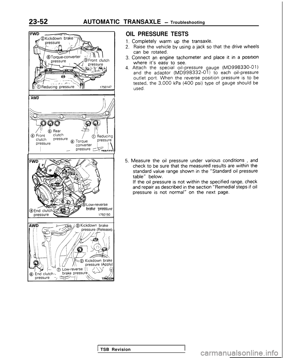
23-52AUTOMATIC TRANSAXLE - Troubleshooting
OIL PRESSURE TESTS
1. Completely
warm
up the
transaxle.
2.Raise the
vehicle
by
using
a jack so that the
drive
wheels
can be
rotated.
3.
Connect
an engine
tachometer
and place it
in a positron
where it’s easy
to
see.
4. Attach
the
special oil-pressure
gauge (MD998330-01)
and
the
adaptor
(MD998332-01) to
each oil-pressure
outlet
port. When
the
reverse position pressure is to
be tested,
the
3,000 kPa (400 psi) type
of gauge should be
used.
I AWUII/I
brake pressure
zT?ziw@
Klckdown
brake
pressure (Release)
5. Measure
the
oil pressure
under
various
conditions
, and check
to be sure that the
measured
results
are within the
standard
value
range shown
in the
“Standard
oil pressure
table”
below.
If the
oil pressure
is not
within the
specified
range, check
and repair
as described
in the
section
“Remedial
steps
if oil
pressure
is not
normal”
on the next
page.
1 TSB Revision1
Page 759 of 1273
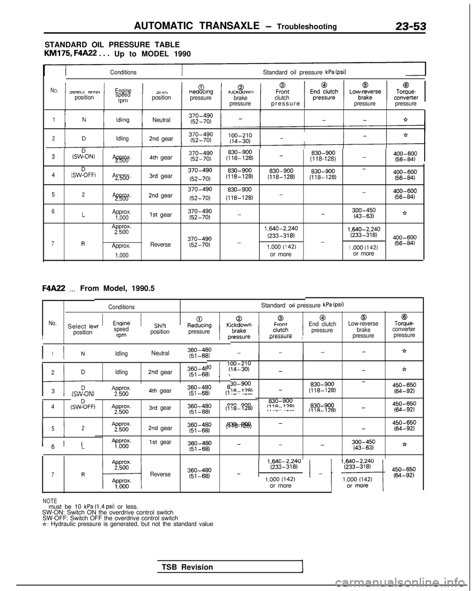
AUTOMATIC TRANSAXLE - Troubleshooting23-53
STANDARD OIL PRESSURE TABLE
KM175,
F4A22
. . .
Up to MODEL 1990
ConditionsStandard oil pressure kPa (psi)
N
O.1p -,-,..,-,,-_1Engine1Ch;J+1-0.1,,._,?...-1F%tclutch1E;;;;;;h1Lov$rse1To;;er13eleLL IfsYCIpositionspeedrpm
cl,1111positionneaucrng
pressurehlCI(aOWrIbrake
pressurepressure )Ipressure pressure
1NldlrngNeutral--*
2DIdling2nd gear 100-210
(14-30)
-
3(SWDON,Approx.830-900 830-900
400-600
--2,5004th gear
(118-128)
(118-128) (56-84)
(SWZFFI
Approx.3rd gear370-490830-900830-900 830-900
400-600-42.500
(52-70) (118-128)
(118-128)
(118-128)
(56-84)
52Approx.
2,5002nd gear370-490830-900 400-600-
(52-70) (118-128)
- (56-84)
-*6LApprox.1st gear370-4901,000
(52-70)-;g:gp
7R
A;pp56od(.
Approx.
1,000
Reverse370-490
(52-70) 1.640-2.240
1.640-2.240
(233-318)(233-318)--1.000 (142)1.OOO (I 42)or more
or moreF4A22
. . .From Model, 1990.5
ConditionsStandard 011 pressure kPa (Psi)
[email protected]“__l__^:__KrlrA,vrrnFrontEnd clutch
Low-reverseTorque-Select leve
brakeconverter
position pressure
‘ressurep-“cxm”1~ ,pressure
pressure
:rspeedcl,,,i;ne”“l;lily wmposition
pressureII
I I360-4801NIdlingNeutral(51~6P’2,--*--
TSB Revision
171 DIdling2nd gear360-4f (51-6b,
, \I
30?y;I;;p-*->i
30-900830-900450-650-1n-17RI- (118-128)(64-92)A2pPg4th gear360-480I I,.lY”-“Iv,(51-681
830-9004(SWZFF)A2pWg.3rdgear
(118-128)
,- .~,,,,“~.--,~.-lL”l,E%830-900-fllR-l='4g::;p
I I52
II
A2pg;.2nd gear~~~~~~p830-900-(118-128)-$g:;p
300-450
-*--”LApP&y.1stgear
(43-63)
1
ICI I
1 EEi2840 / _ 1 ‘~o~$~ ) 4iiIi;p7RReverse360-480
(51-68)
-1.000 (142)or more
NOTEmust be 10 kPa (I .4 psi) or less.
SW-ON: Switch ON the overdrive control switch SW-OFF: Switch OFF the overdrive control switch
*: Hydraulic pressure is generated, but not the standard value
Page 760 of 1273
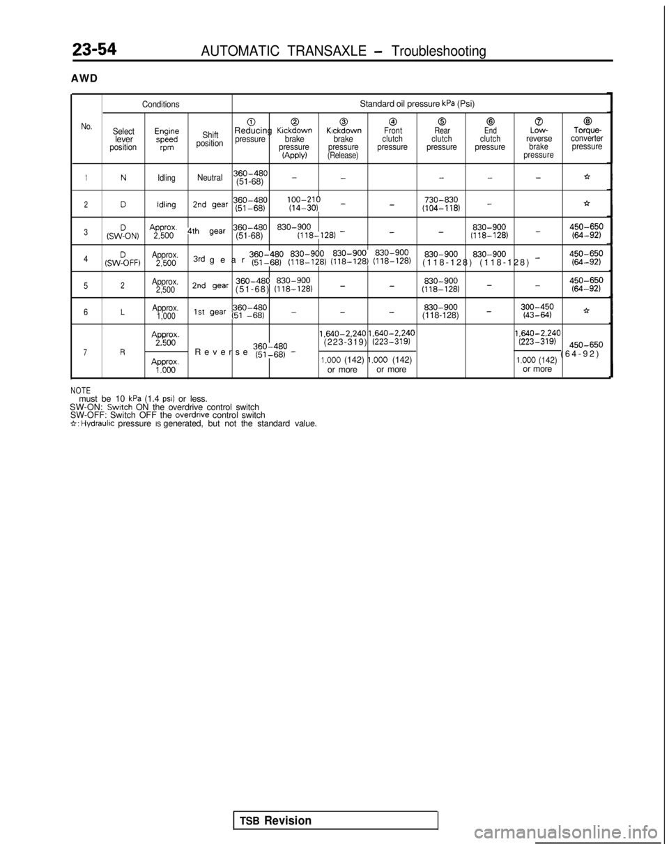
23-54AUTOMATIC TRANSAXLE - Troubleshooting
AWD
ConditionsStandard oil pressure kPa (Psi)
000@0@0@
No.Selectm;;ShiftReducing KickdownKickdownFront RearEndLow-Torque-leverpressurebrake brakeclutch clutch clutchreverseconverter
positionvmposition pressure pressure pressure pressure pressurebrakepressure(Apply)(Release)
pressure
1NIdlingNeutral360-480---*(51-68) --
360-480 lfyfI;;; _ 730-8302Dldlrng2nd war (51-68)
(104-118) -*-
(sw!oN)
AgFil’ 4th gear360-480 830-900 830-900
_3--(51-68)
(118-128)
-(118-128)g:gp 830-900
4(SW%FF)Approx. 830-9002.5003rd gear ~~~I$p (y$$zr (~$$EJ (??i??$)(118-128) (118-128) -g::;p
Approx.2nd gear 360-480 830-900
830-900450-650-52(51-68)
(118-128) _-2,500
(118-128) - (64-92)
6LApprox.360-480
830-9001,0001st gear (51 -66)---(118-128) -;:;I$;*
Ap&;.
1.640-2.240
1.640-2.240 1.640-2.240
7R ’Reverse ~~~$~p -(223-319)
(223-319)(223-319) @O-65,,
(64-92
)
Ap”do”o”.1.000 (142) 1.000 (142)1.000 (142)or more
or more or more
NOTEmust be 10 kPa (1.4 PSI) or less.
SW-ON: Switch ON the overdrive control switch
SW-OFF: Switch OFF the overdrrve control switch6: Hydraulrc pressure IS generated, but not the standard value.
TSB Revision