MITSUBISHI GALANT 1989 Service Repair Manual
Manufacturer: MITSUBISHI, Model Year: 1989, Model line: GALANT, Model: MITSUBISHI GALANT 1989Pages: 1273, PDF Size: 37.62 MB
Page 761 of 1273
AUTOMATIC TRANSAXLE - Troubleshooting23-55
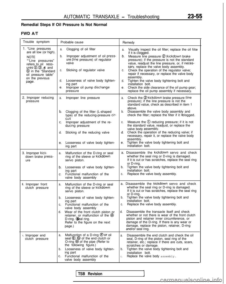
Remedial Steps If Oil Pressure Is Not Normal
FWD A/T Trouble symptom Probable cause Remedy
1. *Line pressuresa.
a.are all low (or high).Clogging of oil filter
Visually inspect the oil filter; replace the oil filte
NOTEb.Improper adjustment of oil press-
if it is cl,ogged.b.Measure line pressure @ (kickdown
brake
*“Line pressures” ure,(line
pressure) of regulator
pressure); if the pressure is not the standard
refers to oil ress-
valve
value, readjust the line pressure, or, if neces-
ures@,@, 4 and
6sary, replace the valve body assembly. @
in the “Standardc.Sticking of regulator valvec.Check the operation of the regulator valve;
oil pressure table” repair if necessary, or replace the valve body
on the previous assembly.
wed.Looseness of valve body tighten-d.Tighten the valve body tightening bolt and
ing part installation bolt.
e.Improper oil pump dischangee.Check the side clearance of the oil pump gear;
pressure replace the oil pump assembly if necessary.
2. Improper reducing
a.Improper line pressurea.Check the @ kickdown
brake pressure /line
pressure pressure); if the line pressure is not the
standard value, check as described in item 1
above.
b.Clogging of the filter (L-shapedb.Disassemble the valve body assembly and
type) of the reducing-pressure cir-
check the filter; replace the filter if it is clogged.
cuitc.Improper adjustment of the re-c.Measure the @ reducing pressure; if it is not
ducing
pressure the standard value, readjust, or replace the
valve body assembly.
d.Sticking of the reducing valved.Check the operation of the reducing valve; if
necessary, repair it, or replace the valve body
assembly.
e.Looseness of valve body tighten-e.Tighten the valve body tightening bolt and
ing part installation bolt.
3. Improper
kick-a.Malfunction of the D-ring or seal a. Disassemble the kickdown
servo and check
down brake press-
ring of the sleeve or kickdown
whether the seal ring or D-ring is damaged.
ure servo piston. If it is cut or has scratches, replace the seal ring
or D-ring.
b.Looseness of valve body tighten-b.Tighten the valve body tightening bolt and
ing part installation bolt.
c.Functional malfunction of thec.Replace the valve body assembly.
valve body assembly
1. Improper front clutch pressurea.Malfunction of the D-ring or seal a. Disassemble the kickdown
servo and check
ring of the sleeve or kickdown
whether the seal ring or D-ring is damaged.
servo piston. If it is cut or has scratches, replace the seal ring
or D-ring.
b.Looseness of valve body tighten-b.Tighten the valve body tightening bolt and
ing part installation bolt.
c.Functional malfunction of thec.Replace the valve body assembly.
valve body assembly
d.Wear of the front clutch piston ord.Disassemble the transaxle itself and check
retainer, or malfunction of the @
whether or not there is wear of the front clutch
D-ring. @ seal ring.
piston and retainer inner circumference, or
Refer to the figure on the next damage of the D-ring. If there is any wear or
page.) damage, replace the piston, retainer, D-ring and/or
seal ring.
i. Improper end
clutch pressurea.Malfunction of a D-ring @or oila.Disassemble the end clutch and check the oil
seal 0.0 of the end clutch or
O-ring 8 of the pipe (Refer to seal, D-ring of the piston, seal ring of the
the following figure.) retainer, etc.; replace if there are cuts, scars,
scratches or damage.
b.Looseness of valve body tighten-b.Tighten the valve body tightening bolt and
ing part installation bolt.
c.Functional malfunction of thec.Replace the valve body assembly.valve body assembly
TSB Revision
Page 762 of 1273
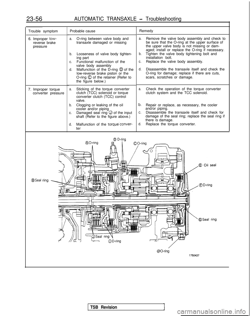
23-56AUTOMATIC TRANSAXLE - Troubleshooting
Trouble symptom
6. Improper low-
reverse brake
pressure Probable cause
a.O-ring between valve body and
transaxle damaged or missing
b.Looseness of valve body tighten-
ing part
c.Functional malfunction of the
valve body assembly
d.Malfunction of the D-ring 0 of the
low-reverse brake piston or the
O-ring
0 of the retainer (Refer to
the figure below.)
a.Sticking of the torque converter
clutch (TCC) solenoid or torque
converter clutch (TCC) control
valve.
b.Clogging or leaking of the oil
cooler and/or piping
c.Damaged seal ring Q of the input
shaft (Refer to the figure above.)
d.Malfunction of the torque’conver-
ter
7. Improper torque
converter pressure
0 D-ring
Remedy
a.Remove the valve body assembly and check to
be sure that the O-ring at the upper surface of
the upper valve body is not missing or dam-
aged; install or replace the O-ring if necessary.
b.Tighten the valve body tightening bolt and installation bolt.
c.Replace the valve body assembly.
d.Disassemble the transaxle itself and check the
O-ring for damage; replace if there are cuts,
scars, scratches or damage.
a.Check the operation of the torque converter
clutch system and the TCC solenoid.
b.Repair or replace, as necessary, the cooler
and/or piping.
c.Disassemble the transaxle itself and check for
damage of the seal ring; replace the seal ring if
there
7s damage.d.Replace the torque converter.
@Seal ring
@O-ring
TSB Revision
Page 763 of 1273
AUTOMATIC TRANSAXLE - Troubleshootinn
23-57
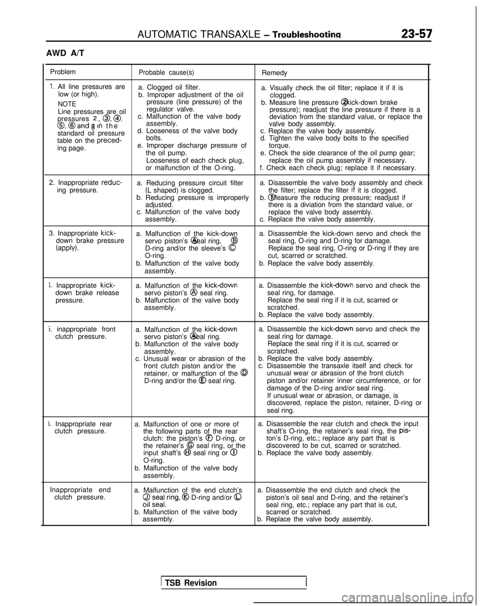
AWD A/T
Problem
Probable cause(s)Remedy
1. All line pressures are a. Clogged oil filter.
low (or high). a. Visually check the oil filter; replace it if it is
b. Improper adjustment of the oil clogged.
NOTEpressure (line pressure) of the
b. Measure line pressure @ (kick-down brake
Line pressures are oil regulator valve.
pressure); readjust the line pressure if there is a
pressures
2 ,, 0, @,
8 c. Malfunction of the valve body
deviation from the standard value, or replace the0, @and 7 In th
e
assembly.
valve body assembly.
standard oil pressure d. Looseness of the valve body
c. Replace the valve body assembly.
table on the preced-
bolts.
d. Tighten the valve body bolts to the specified
ing page. e. Improper discharge pressure of
torque.
the oil pump. e. Check the side clearance of the oil pump gear;
Looseness of each check plug, replace the oil pump assembly if necessary.
or malfunction of the O-ring. f. Check each check plug; replace it if necessary.
2. Inappropriate reduc-
a. Reducing pressure circuit filter a. Disassemble the valve body assembly and check
ing pressure.
(L shaped) is clogged. the filter; replace the filter if
it is clogged.b. Reducing pressure is improperly b. @ Measure the reducing pressure; readjust if
adjusted. there is a diviation from the standard value, or
c. Malfunction of the valve body replace the valve body assembly.
assembly. c. Replace the valve body assembly.
3. Inappropriate kick-
a. Malfunction of the kick-down a. Disassemble the kick-down servo and check the
down brake pressure servo piston’s @ seal ring,
43seal ring, O-ring and D-ring for damage.
(appb).D-ring and/or the sleeve’s 0Replace the seal ring, O-ring or D-ring if they are
O-ring. cut, scarred or scratched.
b. Malfunction of the valve body b. Replace the valve body assembly.
assembly.
1. Inappropriate kick-
down brake release
pressure. a. Malfunction of the kickdownservo piston’s @
seal ring.
b. Malfunction of the valve body assembly. a. Disassemble the kickdown servo and check the
seal ring, for damage. Replace the seal ring if it is cut, scarred or
scratched.
b. Replace the valve body assembly.
j. inappropriate front clutch pressure. a. Malfunction of the kickdowna. Disassemble the kickdown servo and check the
servo piston’s @ seal ring.
seal ring for damage.
b. Malfunction of the valve body Replace the seal ring if it is cut, scarred or
assembly. scratched.
c. Unusual wear or abrasion of the b. Replace the valve body assembly.
front clutch piston and/or the c. Disassemble the transaxle itself and check for
retainer, or malfunction of the
0unusual wear or abrasion of the front clutch
D-ring and/or the @
seal ring. piston and/or retainer inner circumference, or for
damage of the D-ring and/or seal ring.
If unusual wear or abrasion, or damage, is
discovered, replace the piston, retainer, D-ring or
seal ring.
j. Inappropriate rear clutch pressure. a. Malfunction of one or more of
the following parts of the rearclutch: the piston’s
@I D-ring, or
the retainer’s 68 seal ring, or the
input shaft’s @I seal ring or @
O-ring.
b. Malfunction of the valve body assembly. a. Disassemble the rear clutch and check the input
shaft’s O-ring, the retainer’s seal ring, the pis-
ton’s D-ring, etc.; replace any part that is
discovered to be cut, scarred or scratched.
b. Replace the valve body assembly.
Inappropriate end clutch pressure. a. Malfunction of the end clutch’s
($ z;ea/,ring, @I D-ring and/or 0
b. Malfunction of the valve body
assembly. a. Disassemble the end clutch and check the
piston’s oil seal and D-ring, and the retainer’s
seal ring, etc.; replace any part that is cut,
scarred or scratched.
b. Replace the valve body assembly.
1 TSB Revision
Page 764 of 1273
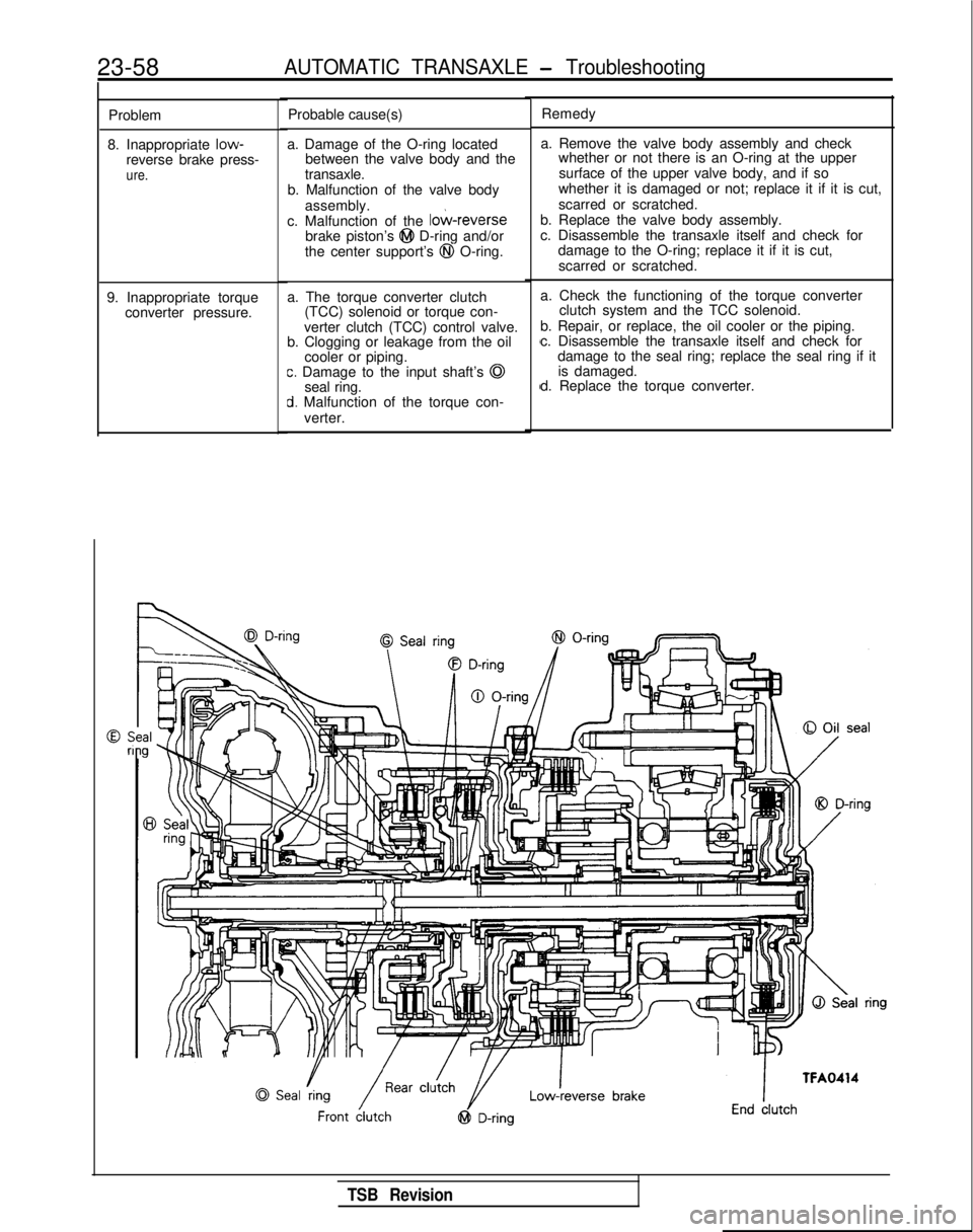
23-58AUTOMATIC TRANSAXLE - Troubleshooting
Problem
8. Inappropriate low-
reverse brake press-
ure.
9. Inappropriate torque converter pressure. Probable cause(s)
a. Damage of the O-ring located between the valve body and the
transaxle.
b. Malfunction of the valve body
assembly.
c. Malfunction of the
lo&reversebrake piston’s @I D-ring and/or
the center support’s @I O-ring.
a. The torque converter clutch (TCC) solenoid or torque con-
verter clutch (TCC) control valve.
b. Clogging or leakage from the oil
cooler or piping.
c. Damage to the input shaft’s @
seal ring.
d. Malfunction of the torque con-
verter. Remedy
a. Remove the valve body assembly and check whether or not there is an O-ring at the upper
surface of the upper valve body, and if so
whether it is damaged or not; replace it if it is cut,
scarred or scratched.
b. Replace the valve body assembly.
c. Disassemble the transaxle itself and check for damage to the O-ring; replace it if it is cut,
scarred or scratched.
a. Check the functioning of the torque converter clutch system and the TCC solenoid.
b. Repair, or replace, the oil cooler or the piping.
c. Disassemble the transaxle itself and check for damage to the seal ring; replace the seal ring if itis damaged.
d. Replace the torque converter.
TSB Revision
Page 765 of 1273
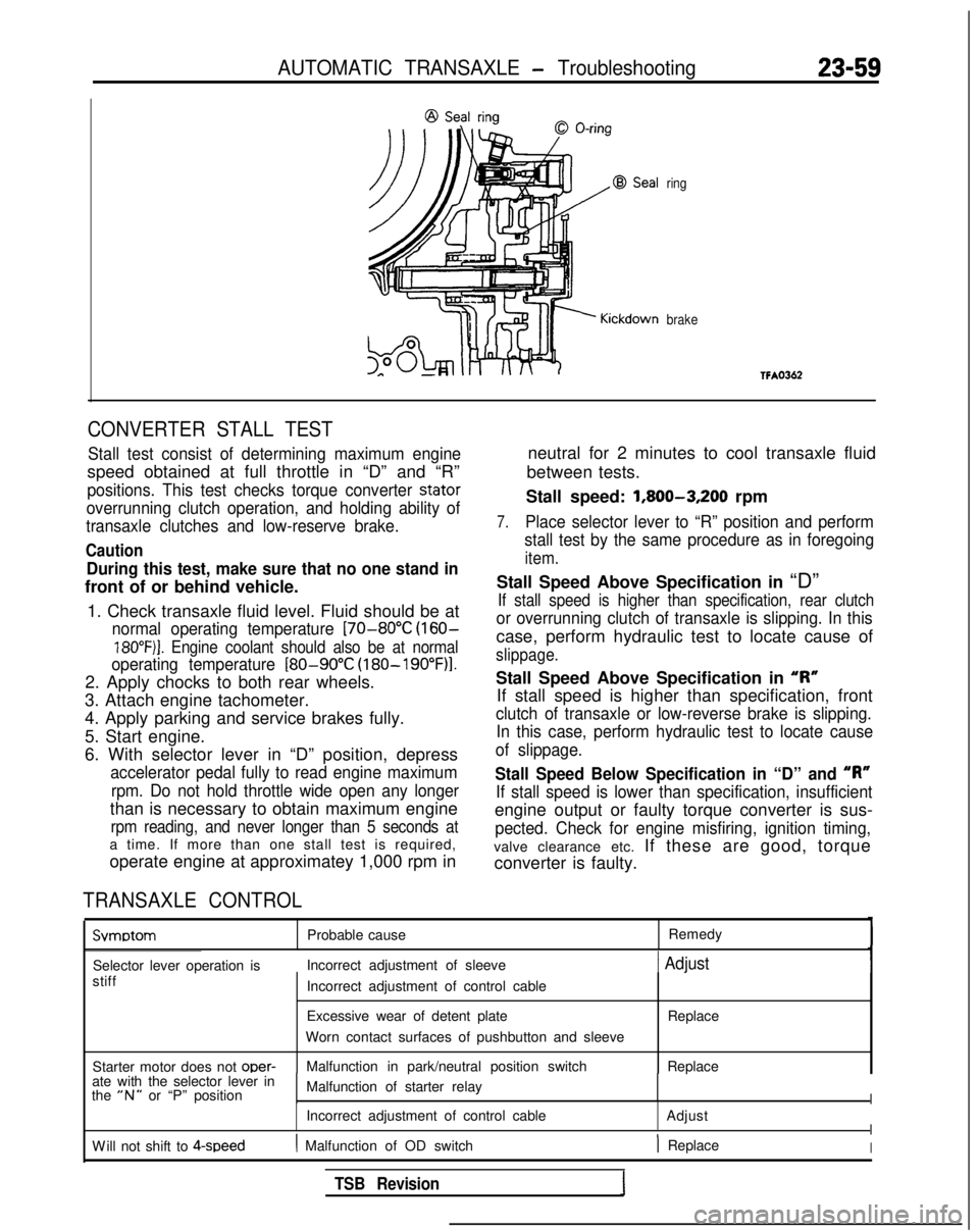
AUTOMATIC TRANSAXLE - Troubleshooting23-59
ring
brake
CONVERTER STALL TEST
Stall test consist of determining maximum engine
speed obtained at full throttle in “D” and “R”
positions. This test checks torque converter stator
overrunning clutch operation, and holding ability of
transaxle clutches and low-reserve brake.
Caution
During this test, make sure that no one stand in
front of or behind vehicle.
1. Check transaxle fluid level. Fluid should be at
normal operating temperature [70-80°C (160-
18O”F)j. Engine coolant should also be at normal
operating temperature
[80-90°C (180-19O”F)l.
2. Apply chocks to both rear wheels.
3. Attach engine tachometer.
4. Apply parking and service brakes fully.
5. Start engine.
6. With selector lever in “D” position, depress
accelerator pedal fully to read engine maximum
rpm. Do not hold throttle wide open any longer
than is necessary to obtain maximum engine
rpm reading, and never longer than 5 seconds at
a time. If more than one stall test is required,
operate engine at approximatey 1,000 rpm in
TRANSAXLE CONTROL
neutral for 2 minutes to cool transaxle fluid
between tests.
Stall speed: 1,800-3,200
rpm
7.Place selector lever to “R” position and perform
stall test by the same procedure as in foregoing
item.
Stall Speed Above Specification in “D”
If stall speed is higher than specification, rear clutch
or overrunning clutch of transaxle is slipping. In this
case, perform hydraulic test to locate cause of
slippage.
Stall Speed Above Specification in “I?”
If stall speed is higher than specification, front
clutch of transaxle or low-reverse brake is slipping. In this case, perform hydraulic test to locate cause
of slippage.
Stall Speed Below Specification in “D” and “R”
If stall speed is lower than specification, insufficient
engine output or faulty torque converter is sus-
pected. Check for engine misfiring, ignition timing,
valve clearance etc. If these are good, torque
converter is faulty. Svmotom
Probable cause
Remedy
Selector lever operation is Incorrect adjustment of sleeve
1 Adjust
stiff
Starter motor does not oper-
Incorrect adjustment of control cable
Excessive wear of detent plate
Worn contact surfaces of pushbutton and sleeve
Malfunction in park/neutral position switch Replace
Replace
ate with the selector lever in
the
“N” or “P” position Malfunction of starter relayI
Incorrect adjustment of control cable
AdjustI
W
ill not shift to 4-speed
( Malfunction of OD switch) ReplaceI
TSB Revision
Page 766 of 1273
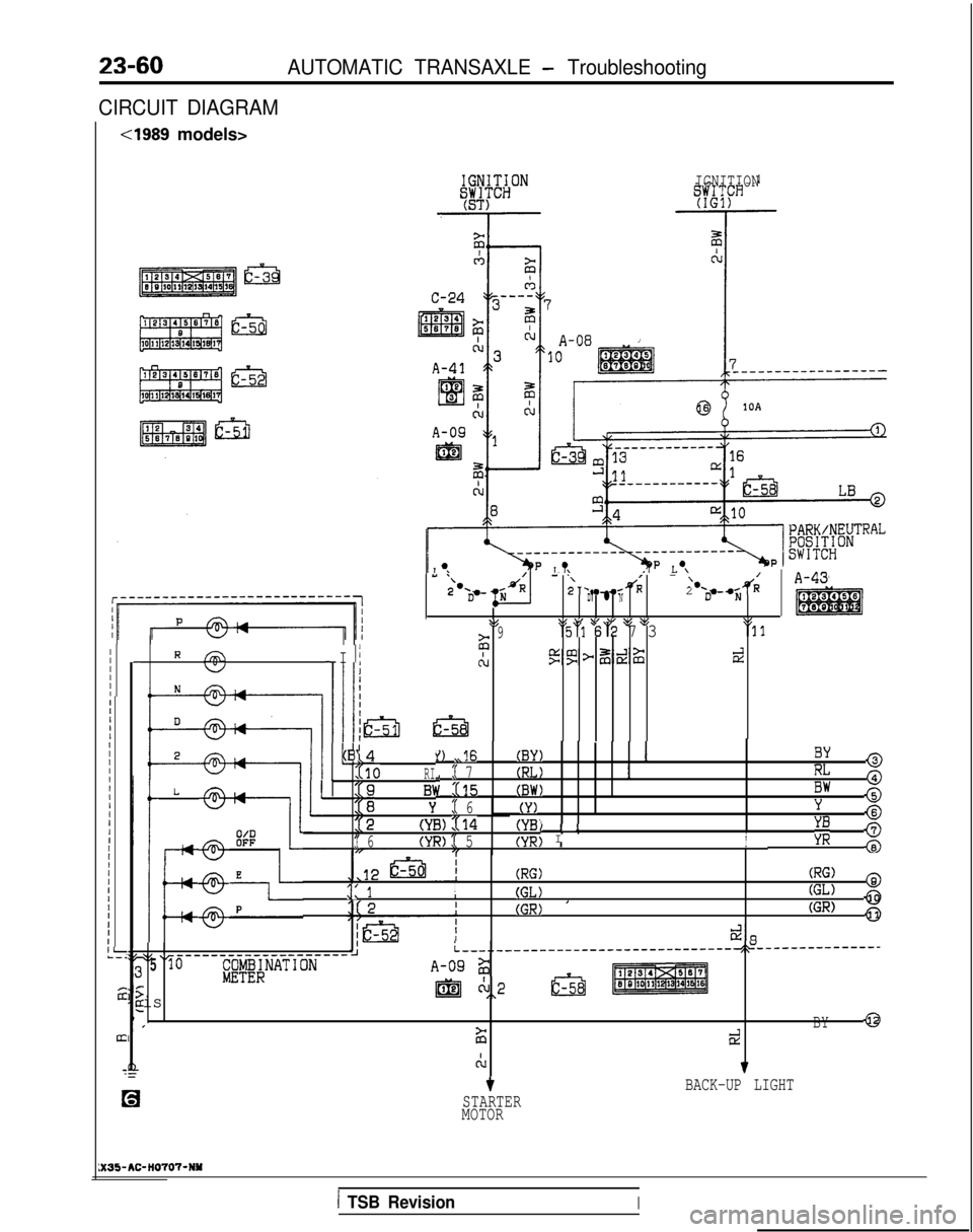
23-60AUTOMATIC TRANSAXLE - Troubleshooting
CIRCUIT DIAGRAM
cl989 models>
IGNITION
- ‘\- ‘\I-/.d2 -s/R‘*A-432.‘Da-2‘-- RD* l ND N
\$\I \I $6 >’ pg $5\I
- I 1:29‘ki 62 7 3'11
AJ5gp&%dII -IIIIIII1IIIIIIIIIIIIIIIIIIIIIIIIII-*-:
;2
III
:
R fiKJ
Ill,14(B'
1I10RI
1' 2i
B1I
Y:( 6
12(YB)114(YB'
:( 6(YR):( 5(YR;1I
0 ,16(BY)I
:( 7By @
; x15
(RL)IRL @(BW)BW @(Y)Y,"I2@I I1I\ II;;; 8
L
I--+
P
-@
@-
-@-
(RG)
:: 1I(GL)
(RG) @
I
(GR) '
(GL) a
(GR)0
&iL__-..___-------------------------~~---------------$5 ‘r-----_______________510;gyg;NATIONA-092
is
@jJA2,\
rBY43
2Et?
CL7
tBACK-UP LIGHT
STARTER
MOTOR
:X35-AC-H0707-NY
1 TSB RevisionI
Page 767 of 1273
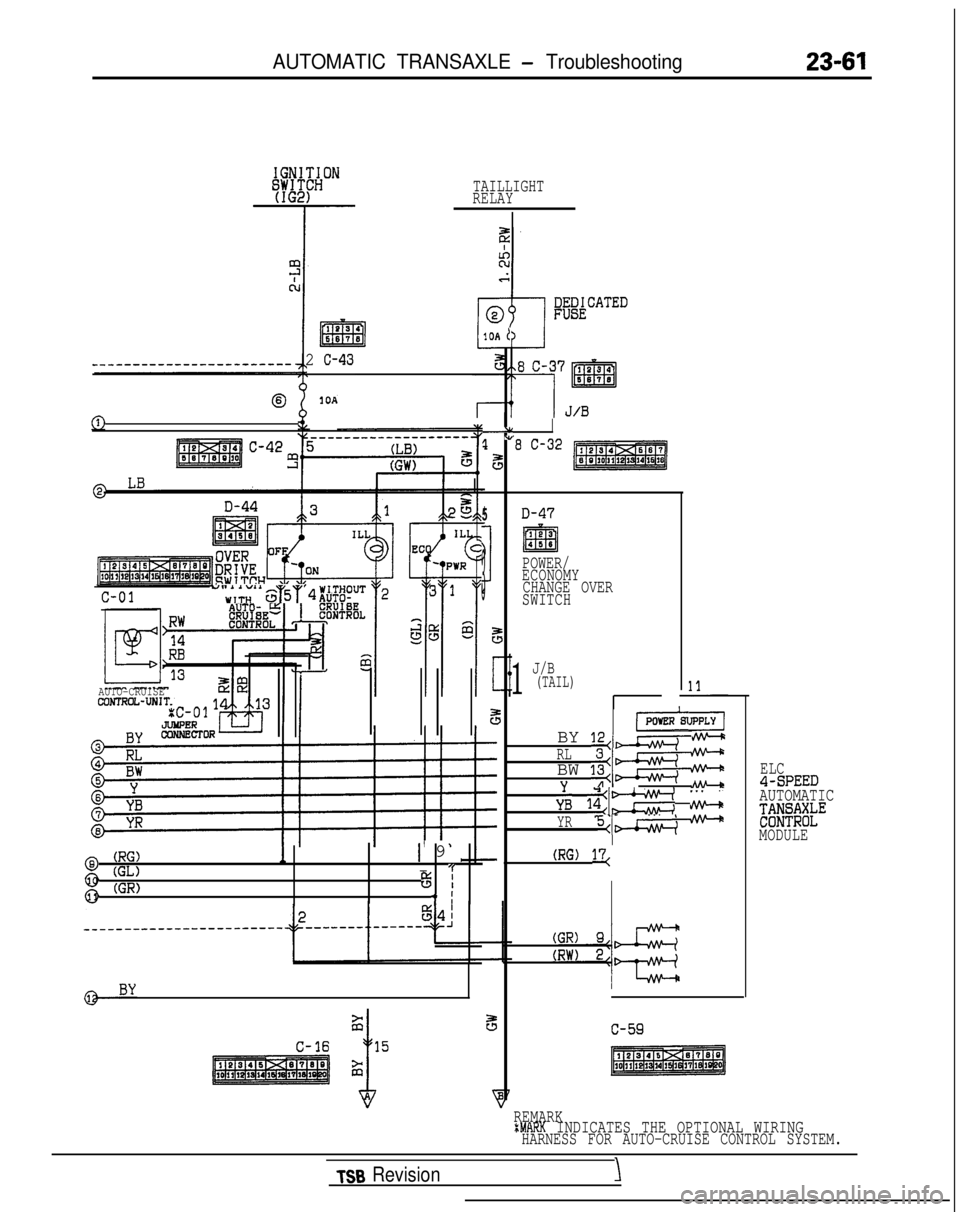
AUTOMATIC TRANSAXLE - Troubleshooting
TAILLIGHT
RELAY
I334m6678
____-__-_--__-----------2 c-43
01OA
@
c-01"'&,"'$,5‘r
AUTO-CRUISECDWROL-UNIT
(RG)@ (GL)
1 9
g (GR)I 'f% I
3 I
C-16
1OA 1
-1
!I ”
5
5
>
1
3
5
5
e
'8 C-32
D-47
POWER/
ECONOMY CHANGE OVER
SWITCH
1
J/B(TAIL)
IPOYER
BY 12,
RLBW 1::s"/I-
;B li:m ki
YR5
ELC4-SPEEDAUTOMATIC
FGEt;;kE
MODULE
REMARK
tMARK INDICATES THE OPTIONAL WIRINGHARNESS FOR AUTO-CRUISE CONTROL SYSTEM.
TSB Revision\
Page 768 of 1273
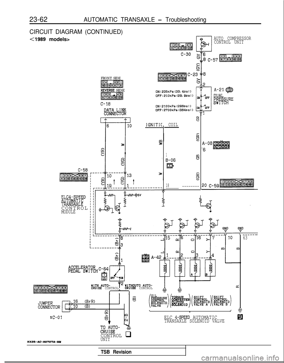
23-62AUTOMATIC TRANSAXLE - Troubleshooting
CIRCUIT DIAGRAM (CONTINUED)
<1989 models>
FRONT SIDE
REVERBE SIDE
C-18
e!T&Lcl%
C-58
ELC4-SPEED
!#i!.E%CECONTRO
L
MODULE
r'.I
AUTO COMPRESSOR
CONTROL UNIT
IIIIIIII1IIIIIII
I
IGNITIC
WITH AUTO-WITHOUT0 AUTO-CRUIBE CONTROLCRUIBE CONTROLI==I I I
( @ (~~~~)~~~~(~~~~)(~~~~~D)
\*ese343cd 7
puJJE'o- -5
CONTROL q
ELC 4-SPEED AUTOMATICTRANSAXLE SOLENOID VALVE
%
COIL
1
B-068
5
18______ --------
A-08
:6
1------63
KXs5-AC-n0707A-nnUNIT
TSB Revision
Page 769 of 1273
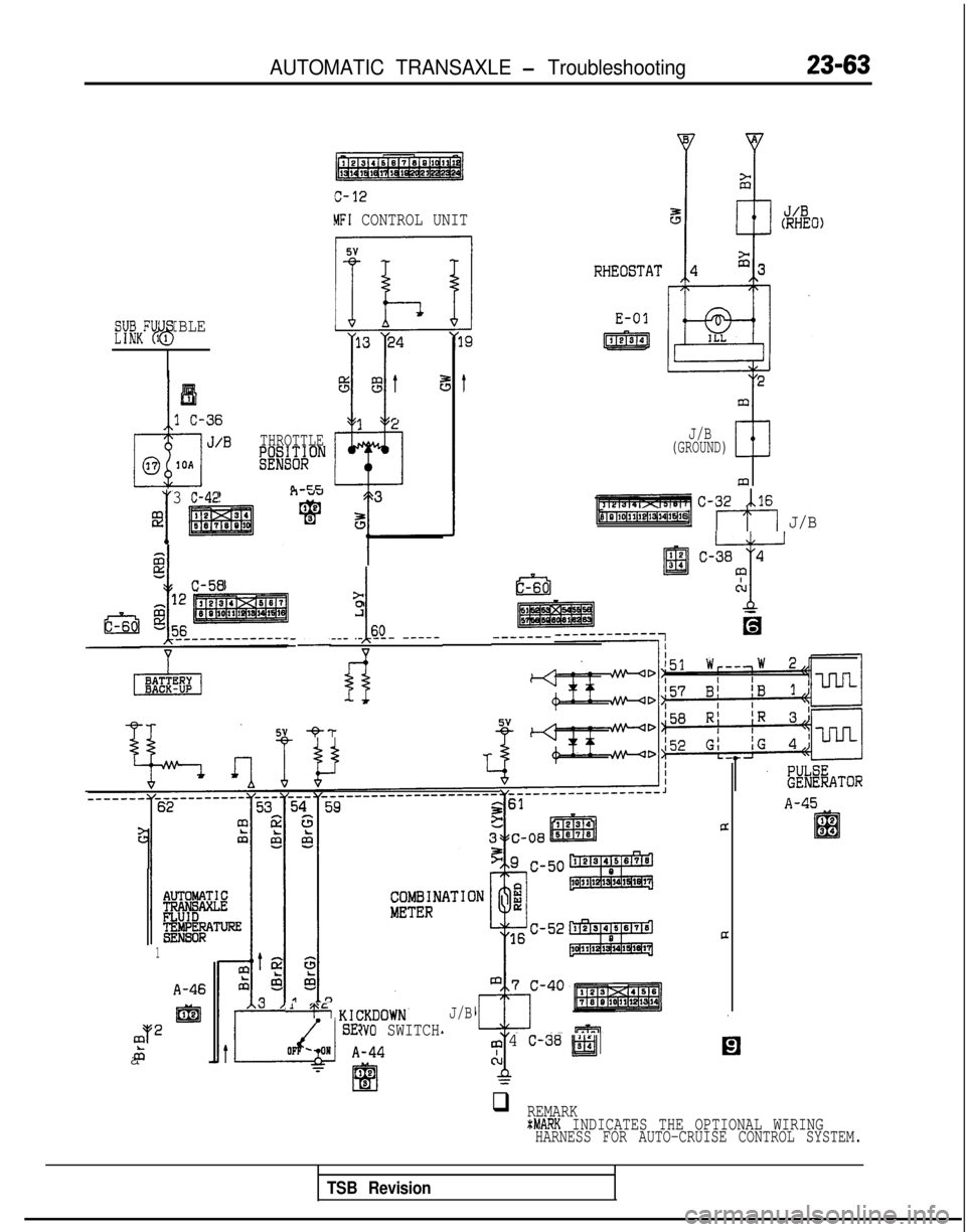
AUTOMATIC TRANSAXLE - Troubleshooting
MFI CONTROL UNIT
THROTTLEW#ON
n cc
E-01
mfY;KFU1 IBLE23
J/B(GROUND)
C-32 xi.16
I
3 C-42E
5 13 ~1~11~1Ef13(14l15#61117 J/B
c-38 4
T
41cu
-c-58>0
i
.___ -’s_Q- -----
fl
,---_-_---
5v 9-T
A-45
1
A-46
a
m
m2
65
+ KlCKDOWNJ/B
iv0 SWITCH4 c-38 wEl
qREMARKtMARK INDICATES THE OPTIONAL WIRINGHARNESS FOR AUTO-CRUISE CONTROL SYSTEM.
TSB Revision
Page 770 of 1273
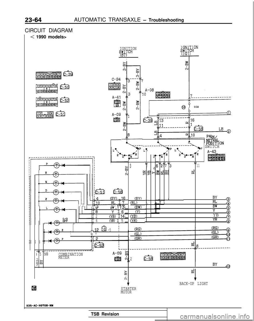
23-64AUTOMATIC TRANSAXLE - Troubleshooting
CIRCUIT DIAGRAM
< 1990 models>
IGNITION
WCH
I
A-09
@
RK/
,_________ -_----__----
L '/p Lo\
J ,"
-LB!f#kONp SWITCH
'*IA-43
a
il-'jR2 -o,-wdRN
Ej2'7 5 113
P
(BY)
(RL)
(BW)
(Y)
(YB)
(YR)
tI I II IBY @
I-I 1
!RL @
Bw @Y
YB $j
YR @
I
R
N
EEi
D
2
II
1 IIai
t5w ,113
Y :tS
:( 2',YB) 114:( 6(YR) J 5IIE.,12E -51I:: 1II
P4
+<
_____--_---__-------
I510COMBINATIONiMETER
;zi
mc:
4
4
L
2E3
I
ciI
t
STARTER
MOTOR BACK-UP LIGHT
X35-AC-HOTOWNY
TSB Revision