MITSUBISHI L200 2004 Owner's Manual (in English)
Manufacturer: MITSUBISHI, Model Year: 2004, Model line: L200, Model: MITSUBISHI L200 2004Pages: 264, PDF Size: 4.14 MB
Page 181 of 264
FOR EMERGENCIES
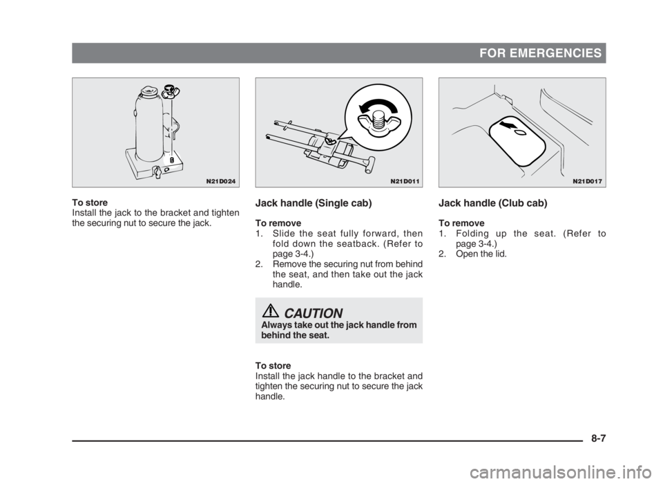
To store
Install the jack to the bracket and tighten
the securing nut to secure the jack.Jack handle (Club cab)
To remove
1. Folding up the seat. (Refer to
page 3-4.)
2. Open the lid.
Jack handle (Single cab)
To remove
1. Slide the seat fully forward, then
fold down the seatback. (Refer to
page 3-4.)
2. Remove the securing nut from behind
the seat, and then take out the jack
handle.
CAUTION Always take out the jack handle from
behind the seat.
To store
Install the jack handle to the bracket and
tighten the securing nut to secure the jack
handle.
8-7
N21D011N21D017N21D024
08engL2_240082_4 22-01-2004 13:10 Page 8-7
Page 182 of 264
FOR EMERGENCIES
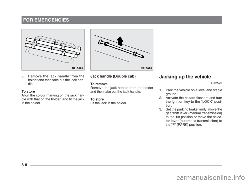
3. Remove the jack handle from the
holder and then take out the jack han-
dle.
To store
Align the colour marking on the jack han-
dle with that on the holder, and fit the jack
in the holder.Jack handle (Double cab)
To remove
Remove the jack handle from the holder
and then take out the jack handle.
To store
Fit the jack in the holder.
Jacking up the vehicle
EN22AACf
1. Park the vehicle on a level and stable
ground.
2. Activate the hazard flashers and turn
the ignition key to the “LOCK” posi-
tion.
3. Set the parking brake firmly, move the
gearshift lever (manual transmission)
to the 1st position or move the selec-
tor lever (automatic transmission) to
the “P” (PARK) position.
8-8
N21D025N21D020
08engL2_240082_4 22-01-2004 13:10 Page 8-8
Page 183 of 264
FOR EMERGENCIES
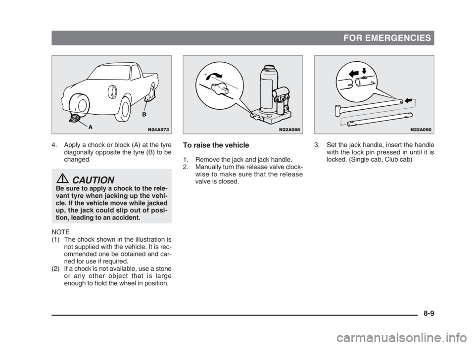
4. Apply a chock or block (A) at the tyre
diagonally opposite the tyre (B) to be
changed.
CAUTIONBe sure to apply a chock to the rele-
vant tyre when jacking up the vehi-
cle. If the vehicle move while jacked
up, the jack could slip out of posi-
tion, leading to an accident.
NOTE
(1) The chock shown in the illustration is
not supplied with the vehicle. It is rec-
ommended one be obtained and car-
ried for use if required.
(2) If a chock is not available, use a stone
or any other object that is large
enough to hold the wheel in position.
3. Set the jack handle, insert the handle
with the lock pin pressed in until it is
locked. (Single cab, Club cab)To raise the vehicle
1. Remove the jack and jack handle.
2. Manually turn the release valve clock-
wise to make sure that the release
valve is closed.
8-9
N22A066N22A080N24A073
B
A
08engL2_240082_4 22-01-2004 13:10 Page 8-9
Page 184 of 264
FOR EMERGENCIES
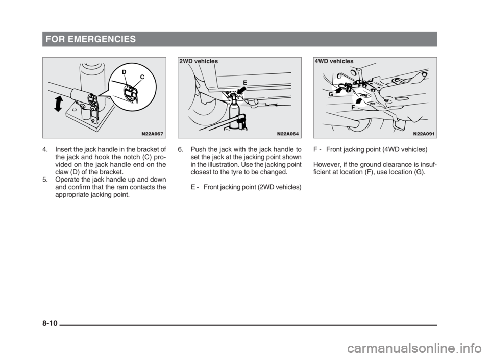
4. Insert the jack handle in the bracket of
the jack and hook the notch (C) pro-
vided on the jack handle end on the
claw (D) of the bracket.
5. Operate the jack handle up and down
and confirm that the ram contacts the
appropriate jacking point.6.Push the jack with the jack handle to
set the jack at the jacking point shown
in the illustration. Use the jacking point
closest to the tyre to be changed.
E - Front jacking point (2WD vehicles)F - Front jacking point (4WD vehicles)
However, if the ground clearance is insuf-
ficient at location (F), use location (G).
8-10
N22A064
E
N22A091
F G
4WD vehicles 2WD vehicles
N22A067
D
C
08engL2_240082_4 22-01-2004 13:10 Page 8-10
Page 185 of 264
FOR EMERGENCIES
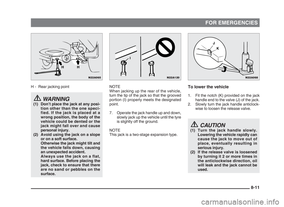
H - Rear jacking point
WARNING(1) Don’t place the jack at any posi-
tion other than the one speci-
fied. If the jack is placed at a
wrong position, the body of the
vehicle could be dented or the
jack might fall over and cause
personal injury.
(2) Avoid using the jack on a slope
or on a soft surface.
Otherwise the jack might tilt and
the vehicle falls down, causing
an unexpected accident.
Always use the jack on a flat,
hard surface. Before placing the
jack, check to ensure that there
are no sand or pebbles on the
surface.
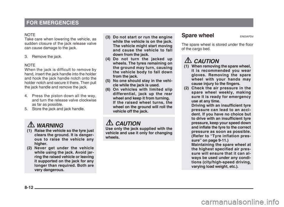
To lower the vehicle
1. Fit the notch (K) provided on the jack
handle end to the valve (J) of the jack.
2. Slowly turn the jack handle anticlock-
wise to loosen the release valve.
CAUTION(1) Turn the jack handle slowly.
Lowering the vehicle rapidly can
cause the jack to move out of
place, eventually resulting in
serious injury.
(2) If the release valve is loosened
by turning it 2 or more times in
the anticlockwise direction, oil
will leak and the jack cannot be
used.
NOTE
When jacking up the rear of the vehicle,
turn the tip of the jack so that the grooved
portion (I) properly meets the designated
point.
7. Operate the jack handle up and down,
slowly jack up the vehicle until the tyre
is slightly off the ground.
NOTE
This jack is a two-stage expansion type.
8-11
N22A120
I
N22A068
K J
N22A065
HH
08engL2_240082_4 22-01-2004 13:10 Page 8-11
Page 186 of 264
FOR EMERGENCIES
NOTE
Take care when lowering the vehicle, as
sudden closure of the jack release valve
can cause damage to the jack.
3. Remove the jack.
NOTE
When the jack is difficult to remove by
hand, insert the jack handle into the holder
and hook the jack handle notch onto the
holder notch and secure it there. Then pull
the jack handle and remove the jack.
4. Press the piston down all the way,
and turn the release valve clockwise
as far as possible.
5. Store the jack and jack handle.
WARNING(1) Raise the vehicle so the tyre just
clears the ground. It is danger-
ous to raise the vehicle any
higher.
(2) Never get under the vehicle
while using the jack. Avoid jar-
ring the raised vehicle or leaving
it supported on the jack for any
longer than required. Both are
very dangerous.
(3) Do not start or run the engine
while the vehicle is on the jack.
The vehicle might start moving
and cause the vehicle to fall
down from the jack.
(4) Do not turn the jacked up
wheels. The tyres remaining on
the ground may turn, causing
the vehicle body to fall down
from the jack.
(5) No one should stay in the vehi-
cle while the jack is used.
(6) On vehicles with limited slip
differential, jack up the rear
wheel and keep it from turning.
If the raised wheel turns, the
wheel on the ground will roll the
vehicle off the jack.
CAUTIONUse only the jack supplied with the
vehicle and use it only for changing
wheels.
Spare wheelEN03APDd
The spare wheel is stored under the floor
of the cargo bed.
CAUTION(1) When removing the spare wheel,
it is recommended you wear
gloves. Removing the spare
wheel with your hands may
cause injury to the fingers.
(2) Check the air pressure in the
spare wheel weekly, making
sure it is ready for emergency
use at any time.
Driving with an insufficient tyre
pressure can lead to an acci-
dent. If you have no choice but
to drive with an insufficient tyre
pressure, keep your speed down
and inflate the tyre to the correct
pressure as soon as possible.
(Refer to “Tyre inflation pres-
sure” on page 9-11.)
Maintaining the spare wheel at
the highest specified air pres-
sure will ensure that it can al-
ways be used under any condi-
tions (city/high-speed driving,
varying load weight, etc.).
8-12
08engL2_240082_4 22-01-2004 13:10 Page 8-12
Page 187 of 264
FOR EMERGENCIES
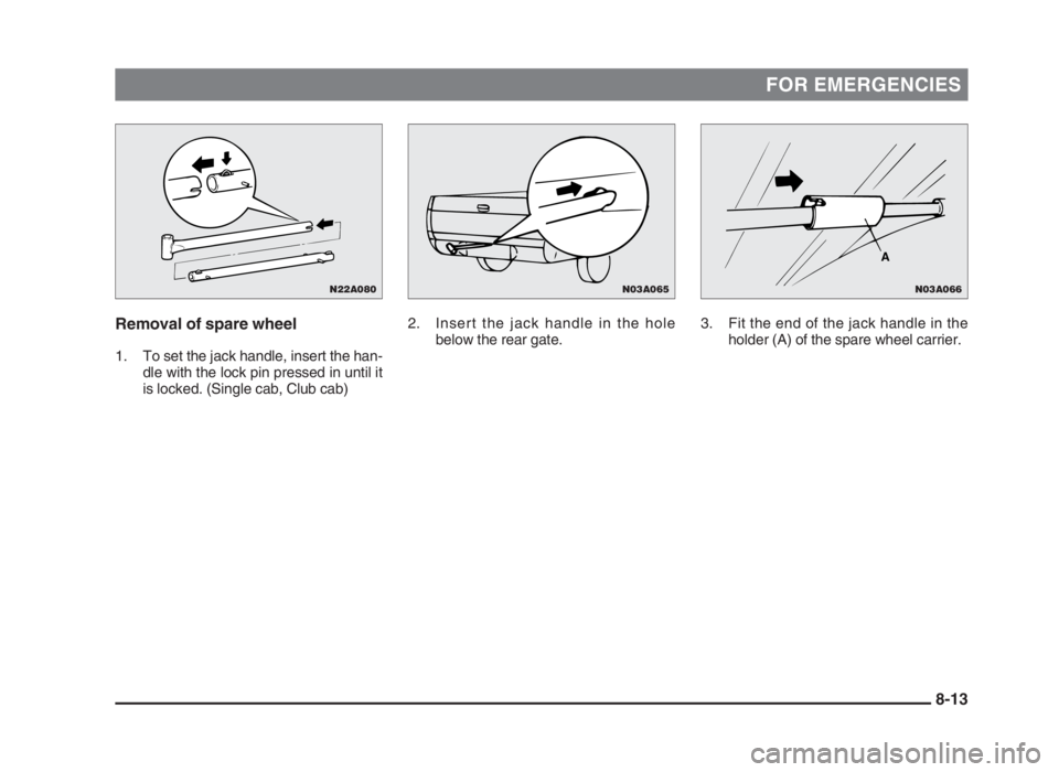
Removal of spare wheel
1. To set the jack handle, insert the han-
dle with the lock pin pressed in until it
is locked. (Single cab, Club cab)3. Fit the end of the jack handle in the
holder (A) of the spare wheel carrier. 2. Insert the jack handle in the hole
below the rear gate.
8-13
N03A066
A
N03A065N22A080
08engL2_240082_4 22-01-2004 13:10 Page 8-13
Page 188 of 264
FOR EMERGENCIES
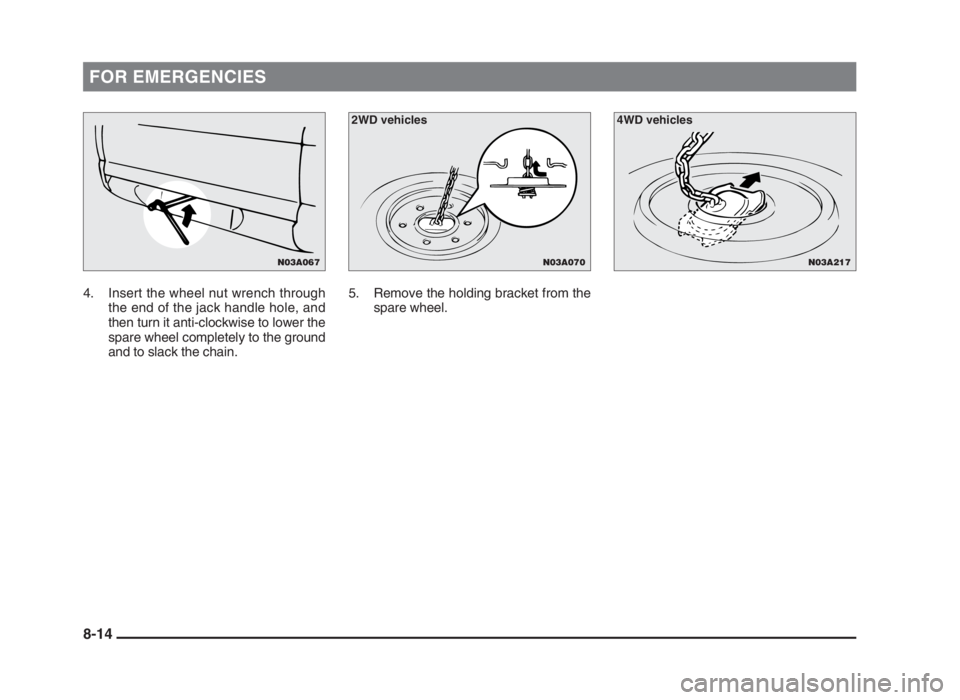
4. Insert the wheel nut wrench through
the end of the jack handle hole, and
then turn it anti-clockwise to lower the
spare wheel completely to the ground
and to slack the chain.5. Remove the holding bracket from the
spare wheel.
8-14
N03A217N03A070
2WD vehicles 4WD vehicles
N03A067
08engL2_240082_4 22-01-2004 13:10 Page 8-14
Page 189 of 264
FOR EMERGENCIES
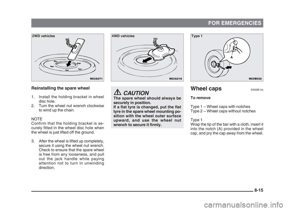
Reinstalling the spare wheel
1. Install the holding bracket in wheel
disc hole.
2. Turn the wheel nut wrench clockwise
to wind up the chain.
NOTE
Confirm that the holding bracket is se-
curely fitted in the wheel disc hole when
the wheel is just lifted off the ground.
3. After the wheel is lifted up completely,
secure it using the wheel nut wrench.
Check to ensure that the spare wheel
is free from any looseness, and pull
out the jack handle while paying
attention not to turn in unwinding
direction.
Wheel capsEN03B-Va
To remove
Type 1 – Wheel caps with notches
Type 2 – Wheel caps without notches
Type 1
Wrap the tip of the bar with a cloth, insert it
into the notch (A) provided in the wheel
cap, and pry the cap away from the wheel.CAUTIONThe spare wheel should always be
securely in position.
If a flat tyre is changed, put the flat
tyre in the spare wheel mounting po-
sition with the wheel outer surface
upward, and use the wheel nut
wrench to secure it firmly.
8-15
N03B022
A
N03A218
4WD vehicles Type 1
N03A071
2WD vehicles
08engL2_240082_4 22-01-2004 13:10 Page 8-15
Page 190 of 264
FOR EMERGENCIES
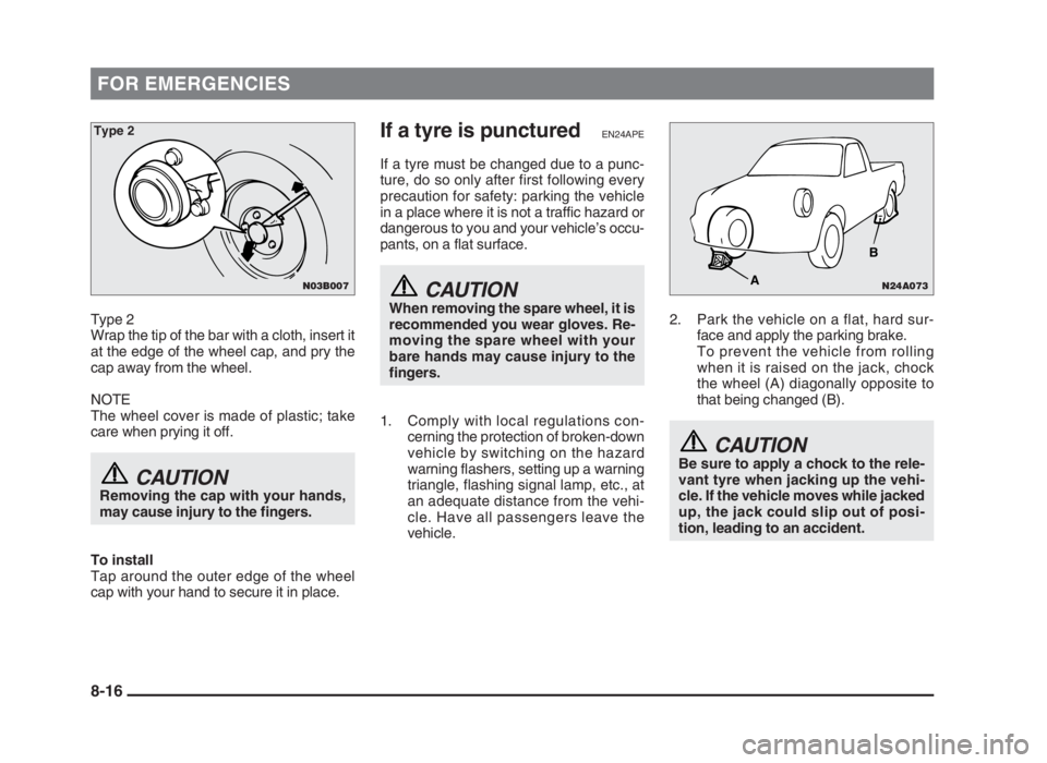
Type 2
Wrap the tip of the bar with a cloth, insert it
at the edge of the wheel cap, and pry the
cap away from the wheel.
NOTE
The wheel cover is made of plastic; take
care when prying it off.
CAUTIONRemoving the cap with your hands,
may cause injury to the fingers.
To install
Tap around the outer edge of the wheel
cap with your hand to secure it in place.
If a tyre is puncturedEN24APE
If a tyre must be changed due to a punc-
ture, do so only after first following every
precaution for safety: parking the vehicle
in a place where it is not a traffic hazard or
dangerous to you and your vehicle’s occu-
pants, on a flat surface.
CAUTIONWhen removing the spare wheel, it is
recommended you wear gloves. Re-
moving the spare wheel with your
bare hands may cause injury to the
fingers.
1. Comply with local regulations con-
cerning the protection of broken-down
vehicle by switching on the hazard
warning flashers, setting up a warning
triangle, flashing signal lamp, etc., at
an adequate distance from the vehi-
cle. Have all passengers leave the
vehicle.2. Park the vehicle on a flat, hard sur-
face and apply the parking brake.
To prevent the vehicle from rolling
when it is raised on the jack, chock
the wheel (A) diagonally opposite to
that being changed (B).
CAUTIONBe sure to apply a chock to the rele-
vant tyre when jacking up the vehi-
cle. If the vehicle moves while jacked
up, the jack could slip out of posi-
tion, leading to an accident.
8-16
N24A073
B
A
N03B007
Type 2
08engL2_240082_4 22-01-2004 13:10 Page 8-16