ignition MITSUBISHI L200 2015 (in English) Repair Manual
[x] Cancel search | Manufacturer: MITSUBISHI, Model Year: 2015, Model line: L200, Model: MITSUBISHI L200 2015Pages: 418, PDF Size: 25.8 MB
Page 293 of 418
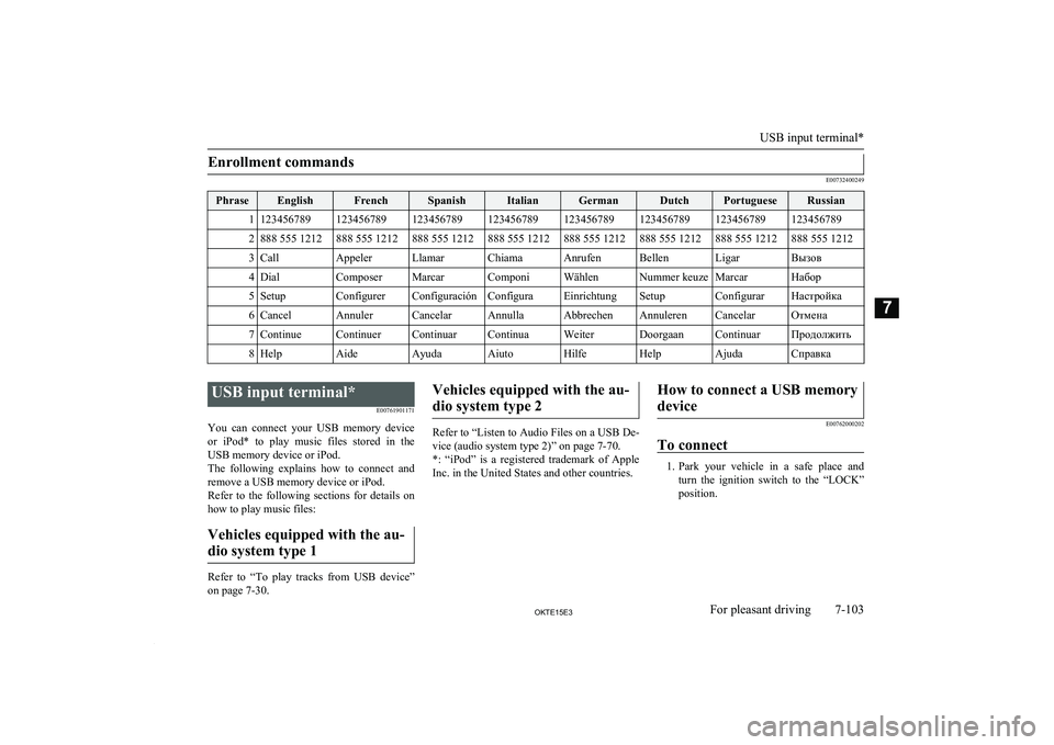
Enrollment commands
E00732400249
PhraseEnglishFrenchSpanishItalianGermanDutchPortugueseRussian11234567891234567891234567891234567891234567891234567891234567891234567892888 555 1212888 555 1212888 555 1212888 555 1212888 555 1212888 555 1212888 555 1212888 555 12123CallAppelerLlamarChiamaAnrufenBellenLigarВызов4DialComposerMarcarComponiWählenNummer keuzeMarcarНабор5SetupConfigurerConfiguraciónConfiguraEinrichtungSetupConfigurarНастройка6CancelAnnulerCancelarAnnullaAbbrechenAnnulerenCancelarОтмена7ContinueContinuerContinuarContinuaWeiterDoorgaanContinuarПродолжить8HelpAideAyudaAiutoHilfeHelpAjudaСправка
USB input terminal*E00761901171
You can connect your USB memory device or iPod* to play music files stored in the USB memory device or iPod.
The following explains how to connect and
remove a USB memory device or iPod.
Refer to the following sections for details on
how to play music files:
Vehicles equipped with the au-dio system type 1
Refer to “To play tracks from USB device”
on page 7-30.
Vehicles equipped with the au-
dio system type 2
Refer to “Listen to Audio Files on a USB De-
vice (audio system type 2)” on page 7-70.
*: “iPod” is a registered trademark of Apple Inc. in the United States and other countries.
How to connect a USB memory
device
E00762000202
To connect
1. Park your vehicle in a safe place and
turn the ignition switch to the “LOCK” position.
USB input terminal*
7-103OKTE15E3For pleasant driving7
Page 294 of 418
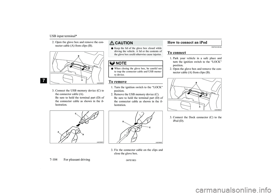
2.Open the glove box and remove the con-
nector cable (A) from clips (B).
3. Connect the USB memory device (C) to
the connector cable (A).
Be sure to hold the terminal part (D) of
the connector cable as shown in the il-
lustration.
CAUTIONl Keep the lid of the glove box closed while
driving the vehicle. A lid or the contents of the glove box could otherwise cause injuries.NOTEl When closing the glove box, be careful not
to trap the connector cable and USB memo- ry device.
To remove
1. Turn the ignition switch to the “LOCK”
position.
2. Remove the USB memory device (C). Be sure to hold the terminal part (D) of
the connector cable as shown in the il-
lustration.
3. Fix the connector cable on the clips and
close the glove box.
How to connect an iPod
E00762100186
To connect
1. Park your vehicle in a safe place and
turn the ignition switch to the “LOCK”
position.
2. Open the glove box and remove the con-
nector cable (A) from clips (B).
3. Connect the Dock connector (C) to the
iPod (D).
USB input terminal*
7-104OKTE15E3For pleasant driving7
Page 295 of 418

NOTElUse a genuine Dock connector from Apple
Inc.
4. Connect the Dock connector (C) to the
connector cable (A).
Be sure to hold the terminal part (E) of the connector cable as shown in the il-
lustration.
CAUTIONl Keep the lid of the glove box closed while
driving the vehicle. A lid or the contents of the glove box could otherwise cause injuries.NOTEl When closing the glove box, be careful not
to trap the connector cable and iPod.
To remove
1. Turn the ignition switch to the “LOCK”
position.
2. Remove the Dock connector (C). Be sure to hold the terminal part (E) ofthe connector cable as shown in the il-
lustration.
3. Fix the connector cable on the clips and
close the glove box.
Types of connectable devices
and supported file specifica-tions
E00762200015
Device types
E00762300306
Devices of the following types can be con- nected.
Model nameConditionUSB memory deviceStorage capacity of
256 Mbytes or moreiPod touch *F/W Ver.1.1.1 or lat-
eriPod classic *F/W Ver.1.0 or lateriPod (fifth genera-
tion) *F/W Ver.1.2.2 or lat-
eriPod nano (fifth gen-
eration) *F/W Ver.1.2 or lateriPod nano (second
generation) *F/W Ver.1.1.2 or lat-
erModels other than
USB memory devi- ces and iPodsDigital audio player
supporting mass stor-
age class* : “iPod touch,” “iPod classic,” “iPod” and
“iPod nano” are registered trademarks of
Apple Inc. in the United States and other
countries.
USB input terminal*
7-105OKTE15E3For pleasant driving7
Page 296 of 418
NOTElDepending on the type of the USB memory
device or other device connected, the con-
nected device may not function properly or the available functions may be limited.
l It is recommended to use an iPod with firm-
ware updated to the latest version.
l You can charge your iPod by connecting it
to the USB input terminal when the ignition switch is in the “ACC” or “ON” position.
l Do not keep your USB memory device or
iPod in your vehicle.
l It is recommended that you back up files in
case of data damage.
l Do not connect to the USB input terminal
any device (hard disk, card reader, memory reader, etc.) other than the connectable devi- ces specified in the previous section. The de-
vice and/or data may be damaged. If any of these devices was connected by mistake, re-move it after turning the ignition switch to
the “LOCK” position.File specifications
E00762400017
You can play music files of the following
specifications that are saved in a USB memo-ry device or other device supporting mass
storage class.
ItemConditionFile formatMP3, WMA, AAC,
WAVItemConditionMaximum number of levels (including the
root)
Level 8
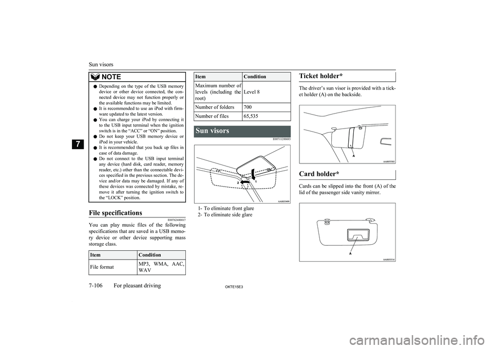
Number of folders700Number of files65,535Sun visors
E00711200693
1- To eliminate front glare2- To eliminate side glare
Ticket holder*
The driver’s sun visor is provided with a tick-
et holder (A) on the backside.
Card holder*
Cards can be slipped into the front (A) of the lid of the passenger side vanity mirror.
Sun visors
7-106OKTE15E3For pleasant driving7
Page 299 of 418
CAUTIONlWhen the cigarette lighter socket is used as a
power source for an electric appliance, be sure that the electric appliance operates at
12 V and has an electric capacity of 120 W or less. In addition, long use of the electricappliance without running the engine may
run down the battery.Accessory socket*
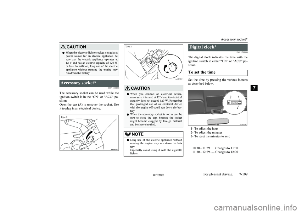
E00711601160
The accessory socket can be used while theignition switch is in the “ON” or “ACC” po-
sition.
Open the cap (A) to uncover the socket. Use it to plug in an electrical device.
Type 1Type 2
CAUTIONl When you connect an electrical device,
make sure it is rated at 12 V and its electrical
capacity does not exceed 120 W. Remember
that prolonged use of an electrical device with the engine off could run down the bat-
tery.
l When the accessory socket is not in use, be
sure to close the cap, because the socket might become clogged by foreign materialand be short-circuited.NOTEl Long use of the electric appliance without
running the engine may run down the bat-
tery.
Especially avoid using it with the cigarette lighter.Digital clock*
E00711700193
The digital clock indicates the time with the
ignition switch in either “ON” or “ACC” po- sition.
To set the time
Set the time by pressing the various buttons
as described below.
1- To adjust the hour
2- To adjust the minutes
3- To reset the minutes to zero
10:30 - 11:29...... Changes to 11:00
11:30 - 12:29...... Changes to 12:00
Accessory socket*
7-109OKTE15E3For pleasant driving7
Page 301 of 418
![MITSUBISHI L200 2015 (in English) Repair Manual 2
(
) -
[Vehicles without central door locks system]
The room lamp goes on when a
door is opened. When all doors
are closed, the room lamp is illu-
minated and dimmed gradually for 7](/img/19/34877/w960_34877-300.png "MITSUBISHI L200 2015 (in English) Repair Manual 2
(
) -
[Vehicles without central door locks system]
The room lamp goes on when a
door is opened. When all doors
are closed, the room lamp is illu-
minated and dimmed gradually for 7")
2
(
) -
[Vehicles without central door locks system]
The room lamp goes on when a
door is opened. When all doors
are closed, the room lamp is illu-
minated and dimmed gradually for 7 seconds then goes out.
However, the lamp goes out im- mediately without being dim-
med when the ignition switch is
turned to the “ON” position.
[Vehicles with central door
locks system]
The room lamp goes on when a
door is opened. When all doors
are closed, the room lamp is illu-
minated and dimmed gradually for 15 seconds then goes out.
However, the lamp goes out im- mediately without being dim-
med in case of the followings:
l All doors are closed and the
ignition switch is turned to the “ON” position.
l All doors are locked using
the key mechanism of the driver’s door, the lock knob
of the driver’s door, or the
remote control switch of the
keyless entry system (if so equipped). NOTEl On vehicles with keyless en-
try system, when the ignition
key is removed with the doors
closed, the lamp is illuminated
and after about 15 seconds it goes off.
The dimming period is also adjustable.
For further information, we
recommend you to consult a
MITSUBISHI MOTORS Au-
thorized Service Point.3
(OFF/
)
-
The lamp goes off.
Personal lamps*
E00712500156
Push the switch (A) to turn on the lamp. Push it again to turn it off.
Door courtesy lamps*
E00717500034
Each door courtesy lamp comes on when the
relevant door is opened and goes off when
the door is closed.
Centre console downlight
E00733300043
The centre console downlight go on when the lamp switch is in the “
” or the “” posi-
tion.
Interior lamps
7-111OKTE15E3For pleasant driving7
Page 310 of 418
If the vehicle breaks downE00800101166
If the vehicle breaks down on the road, move it to the shoulder and use the hazard warning
flashers and/or the warning triangle etc.
Refer to “Hazard warning flasher switch” on page 5-37.
If the engine stops/fails
Vehicle operation and control are affected if
the engine stops.
Before moving the vehicle to a safe area, be aware of the following:
l The brake booster becomes inoperative
and the pedal effort will increase. Press
down the brake pedal harder than usual.
l Since the power steering pump is no lon-
ger operative, the steering wheel feels
heavy when turning it.
Emergency starting
E00800502112
If the engine cannot be started because thebattery is weak or dead, the battery from an-other vehicle can be used with jumper cables to start the engine.
WARNINGl To start the engine using jumper cables
connected from another vehicle, perform
the correct procedures according to the instruction manual. Incorrect procedures could result in a fire or explosion or dam-
age to the vehicles.
1. Get the vehicles close enough so the
jumper cables can reach, but be sure the vehicles aren’t touching each other.If they are, it could cause a ground con-
nection you don’t want. The vehicle will not start, and the bad grounding could
damage the electrical systems.
CAUTIONl Check the other vehicle. It must have a 12-
volt battery.
If the other system isn’t 12-volt, shorting can damage both vehicles.
2. You could be injured if the vehicles
move. Set the parking brake firmly on
each vehicle. Put an automatic transmis-
sion in “P” (PARK) or a manual trans- mission in “N” (Neutral). Turn off the
ignition switch.
WARNINGl Turn off the ignition on both vehicles be-
forehand.
Make sure that the cables or your clothes cannot be caught by the fan or drive belt.
Personal injury could result.NOTEl Turn off all lamps, heater and other electri-
cal loads. This will avoid sparks and help
save both batteries.
3. Make sure battery electrolyte is at the
proper level.
Refer to “Battery” on page 10-10.
WARNINGl If electrolyte fluid is not visible, or ap-
pears to be frozen, Do Not Attempt Jump
Starting!
A battery might rupture or explode if the temperature is below the freezing point orif it is not filled to the proper level.
4. Connect one end of one jumper cable to
the positive (+) terminal of the dis-charged battery (A), and the other end to
the positive (+) terminal of the booster
battery (B).
If the vehicle breaks down
8-02OKTE15E3For emergencies8
Page 321 of 418
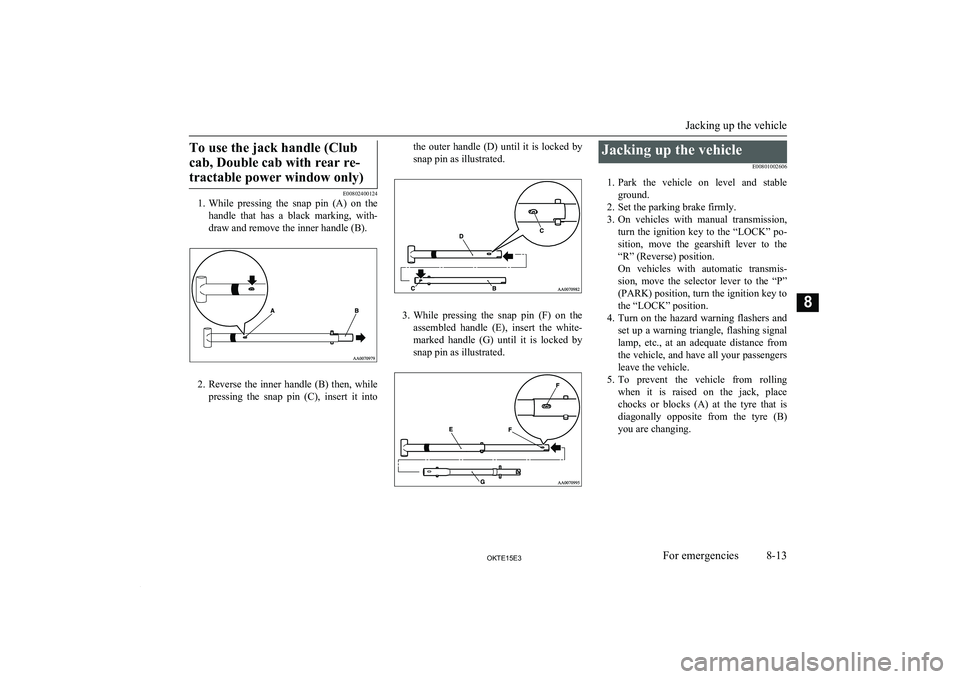
To use the jack handle (Clubcab, Double cab with rear re-tractable power window only)
E00802400124
1. While pressing the snap pin (A) on the
handle that has a black marking, with-draw and remove the inner handle (B).
2. Reverse the inner handle (B) then, while
pressing the snap pin (C), insert it into
the outer handle (D) until it is locked by
snap pin as illustrated.
3. While pressing the snap pin (F) on the
assembled handle (E), insert the white-
marked handle (G) until it is locked by snap pin as illustrated.
Jacking up the vehicle
E00801002606
1. Park the vehicle on level and stable
ground.
2. Set the parking brake firmly.
3. On vehicles with manual transmission,
turn the ignition key to the “LOCK” po-
sition, move the gearshift lever to the “R” (Reverse) position.
On vehicles with automatic transmis- sion, move the selector lever to the “P” (PARK) position, turn the ignition key tothe “LOCK” position.
4. Turn on the hazard warning flashers and
set up a warning triangle, flashing signal lamp, etc., at an adequate distance from
the vehicle, and have all your passengers
leave the vehicle.
5. To prevent the vehicle from rolling
when it is raised on the jack, place
chocks or blocks (A) at the tyre that is diagonally opposite from the tyre (B)
you are changing.
Jacking up the vehicle
8-13OKTE15E3For emergencies8
Page 327 of 418
3.On vehicles with manual transmission,
turn the ignition key to the “LOCK” po-
sition, move the gearshift lever to the “R” (Reverse) position.
On vehicles with automatic transmis- sion, move the selector lever to the “P” (PARK) position, turn the ignition key to
the “LOCK” position.
4. Turn on the hazard warning flashers and
set up a warning triangle, flashing signal lamp, etc., at an adequate distance from
the vehicle, and have all your passengers
leave the vehicle.
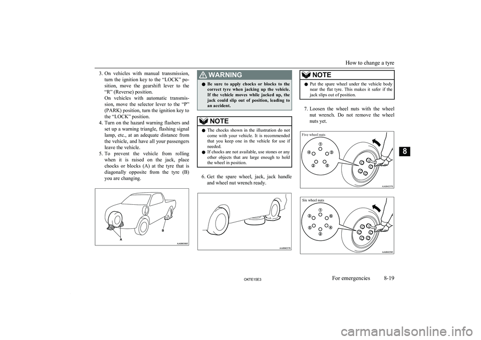
5. To prevent the vehicle from rolling
when it is raised on the jack, place
chocks or blocks (A) at the tyre that is diagonally opposite from the tyre (B)
you are changing.WARNINGl Be sure to apply chocks or blocks to the
correct tyre when jacking up the vehicle.If the vehicle moves while jacked up, the
jack could slip out of position, leading to
an accident.NOTEl The chocks shown in the illustration do not
come with your vehicle. It is recommended
that you keep one in the vehicle for use if needed.
l If chocks are not available, use stones or any
other objects that are large enough to hold the wheel in position.
6. Get the spare wheel, jack, jack handle
and wheel nut wrench ready.
NOTEl Put the spare wheel under the vehicle body
near the flat tyre. This makes it safer if the jack slips out of position.
7. Loosen the wheel nuts with the wheel
nut wrench. Do not remove the wheel nuts yet.
Five wheel nutsSix wheel nuts
How to change a tyre
8-19OKTE15E3For emergencies8
Page 331 of 418
CAUTIONlOn 2WD vehicles, if the transmission is mal-
functioning or damaged, transport the vehi- cle with the driving wheels on a carriage (Type C, D or E) as illustrated.
l If you tow a vehicle with automatic trans-
mission with the driving wheels on the
ground (Type B) as illustrated, make sure
that the towing speed and distance given be- low are never exceeded, causing damage to the transmission.
Towing speed: 50 km/h (30 mph)
Towing distance: 50 km (30 miles)
For the towing speed and the towing dis- tance, follow the local driving laws and reg-
ulations.
Towing with front wheels off
the ground (Type B)
Place the gearshift lever in the “N” (Neutral) position (manual transmission) or the selector
lever in the “N” (NEUTRAL) position (auto- matic transmission).
Release the parking brake.
CAUTIONl Never tow an automatic transmission vehicle
with the front wheels up (and the rear wheels
on the ground) (Type B) when the automatic transmission fluid level is low. This may
cause serious and expensive damage to the
transmission.
Towing with rear wheels off the
ground (Type C)
Place the gearshift lever in the “N” (Neutral)
position (manual transmission) or the selector
lever in the “N” (NEUTRAL) position (auto- matic transmission). Turn the ignition key to
the “ACC” position and secure the steering wheel in a straight ahead position with a rope
or tie-down strap. Never place the ignition switch in the “LOCK” position when towing.
Emergency towing
If towing service is not available in an emer- gency, your vehicle may be temporarily tow-ed by a cable or chain secured to the towinghook.
If your vehicle is to be towed by another ve-
hicle, pay careful attention to the following
points.
If your vehicle is to be towed by
another vehicle
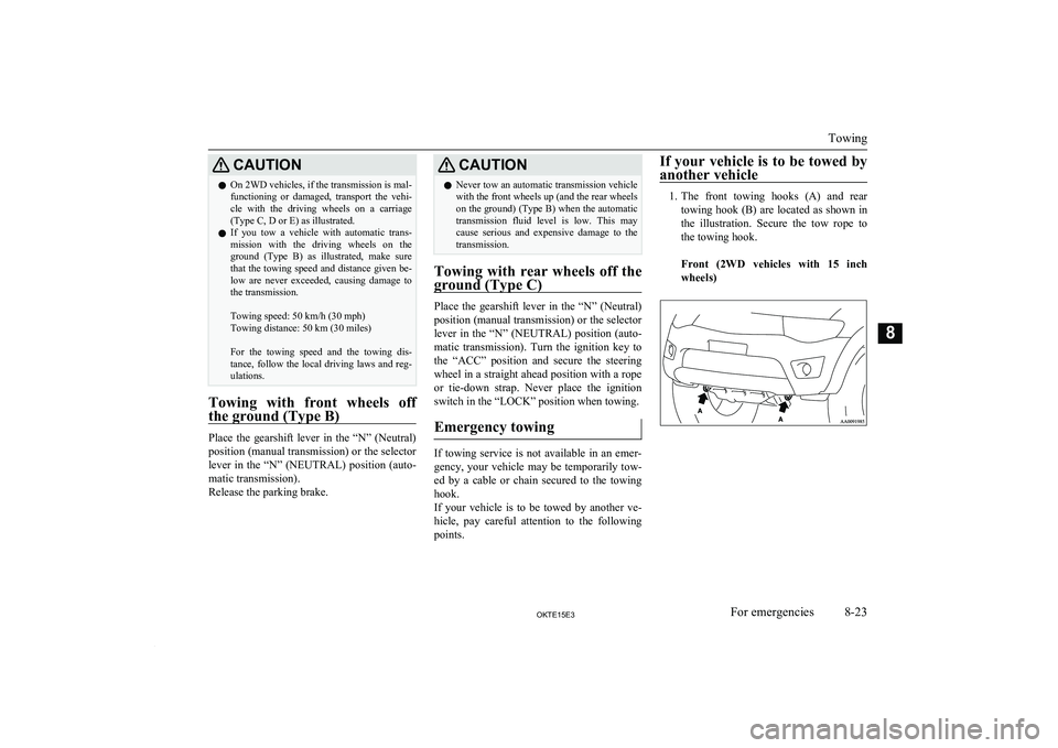
1. The front towing hooks (A) and rear
towing hook (B) are located as shown inthe illustration. Secure the tow rope to
the towing hook.
Front (2WD vehicles with 15 inch wheels)Towing
8-23OKTE15E3For emergencies8