Side MITSUBISHI LANCER 2005 Owner's Manual
[x] Cancel search | Manufacturer: MITSUBISHI, Model Year: 2005, Model line: LANCER, Model: MITSUBISHI LANCER 2005Pages: 788, PDF Size: 45.98 MB
Page 107 of 788
IGNITION SYSTEM
ENGINE ELECTRICAL16-43
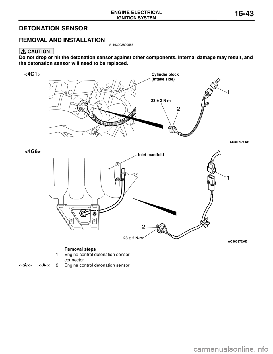
DETONATION SENSOR
REMOVAL AND INSTALLATIONM1163002800556
CAUTION
Do not drop or hit the detonation sensor against other components. Internal damage may result, and
the detonation sensor will need to be replaced.
AC303971
21
23 ± 2 N·m
AB
<4G1>Cylinder block
(Intake side)
AC303972
21
23 ± 2 N·mAB
<4G6>Inlet manifold
Removal steps
1. Engine control detonation sensor
connector
<> >>A<<2. Engine control detonation sensor
Page 111 of 788
ENGINE CONTROL
ENGINE AND EMISSION CONTROL17-3
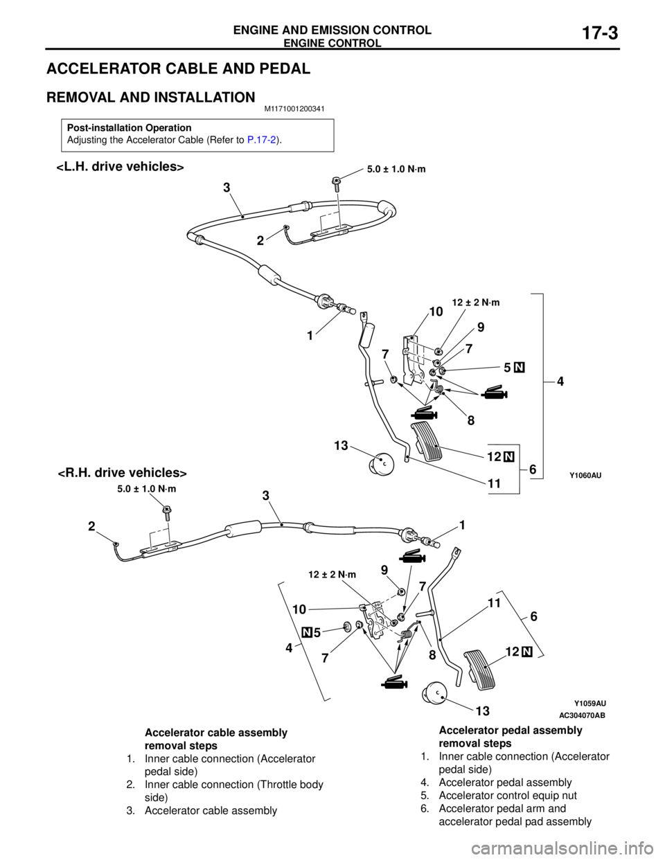
ACCELERATOR CABLE AND PEDAL
REMOVAL AND INSTALLATIONM1171001200341
Post-installation Operation
Adjusting the Accelerator Cable (Refer to P.17-2).
Y1059AU
Y1060AU
AC304070
N
4
5
78 1011
N12
13
AB
1
23
5.0 ± 1.0 N·m
6
12 ± 2 N·m9
7
1 2 3
5.0 ± 1.0 N·m
N
4 5 7
8 10
11
N12 13
6
12 ± 2 N·m
9
7
Accelerator cable assembly
removal steps
1. Inner cable connection (Accelerator
pedal side)
2. Inner cable connection (Throttle body
side)
3. Accelerator cable assemblyAccelerator pedal assembly
removal steps
1. Inner cable connection (Accelerator
pedal side)
4. Accelerator pedal assembly
5. Accelerator control equip nut
6. Accelerator pedal arm and
accelerator pedal pad assembly
Page 116 of 788
EMISSION CONTROL
ENGINE AND EMISSION CONTROL17-8
VACUUM HOSE CHECKM1173007300159
1. Using the piping diagram as a guide, check to be
sure that the vacuum hoses are correctly
connected.
2. Check the connection condition of the vacuum
hoses, (removed, loose, etc.) and check to be
sure that there are no bends or damage.
VACUUM HOSE INSTALLATIONM1173007200107
1. When connecting the vacuum hoses, they should
be securely inserted onto the nipples.
2. Connect the hoses correctly, using the vacuum
hose piping diagram as a guide.
CRANKCASE EMISSION CONTROL
SYSTEM
GENERAL INFORMATION (CRANKCASE
EMISSION CONTROL SYSTEM)
M1173005000237
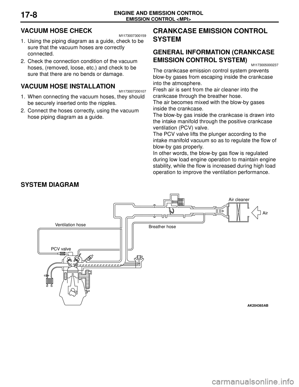
The crankcase emission control system prevents
blow-by gases from escaping inside the crankcase
into the atmosphere.
Fresh air is sent from the air cleaner into the
crankcase through the breather hose.
The air becomes mixed with the blow-by gases
inside the crankcase.
The blow-by gas inside the crankcase is drawn into
the intake manifold through the positive crankcase
ventilation (PCV) valve.
The PCV valve lifts the plunger according to the
intake manifold vacuum so as to regulate the flow of
blow-by gas properly.
In other words, the blow-by gas flow is regulated
during low load engine operation to maintain engine
stability, while the flow is increased during high load
operation to improve the ventilation performance.
SYSTEM DIAGRAM
AK204365
Air cleaner
Air
Ventilation hose
Breather hose
PCV valve
AB
Page 117 of 788
EMISSION CONTROL
ENGINE AND EMISSION CONTROL17-9
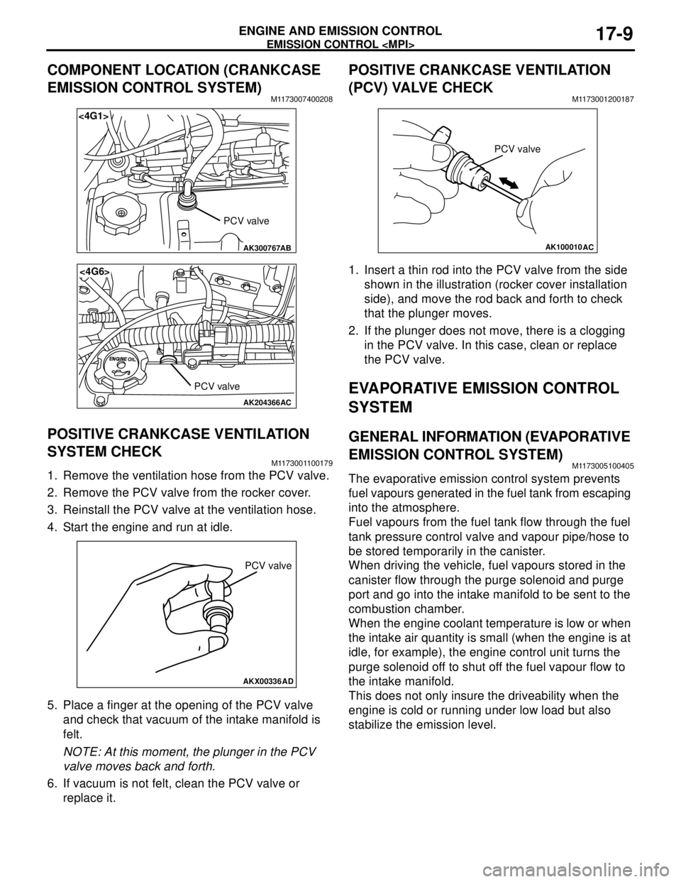
COMPONENT LOCATION (CRANKCASE
EMISSION CONTROL SYSTEM)
M1173007400208
POSITIVE CRANKCASE VENTILATION
SYSTEM CHECK
M1173001100179
1. Remove the ventilation hose from the PCV valve.
2. Remove the PCV valve from the rocker cover.
3. Reinstall the PCV valve at the ventilation hose.
4. Start the engine and run at idle.
5. Place a finger at the opening of the PCV valve
and check that vacuum of the intake manifold is
felt.
NOTE: At this moment, the plunger in the PCV
valve moves back and forth.
6. If vacuum is not felt, clean the PCV valve or
replace it.
POSITIVE CRANKCASE VENTILATION
(PCV) VALVE CHECK
M1173001200187
1. Insert a thin rod into the PCV valve from the side
shown in the illustration (rocker cover installation
side), and move the rod back and forth to check
that the plunger moves.
2. If the plunger does not move, there is a clogging
in the PCV valve. In this case, clean or replace
the PCV valve.
EVAPORATIVE EMISSION CONTROL
SYSTEM
GENERAL INFORMATION (EVAPORATIVE
EMISSION CONTROL SYSTEM)
M1173005100405
The evaporative emission control system prevents
fuel vapours generated in the fuel tank from escaping
into the atmosphere.
Fuel vapours from the fuel tank flow through the fuel
tank pressure control valve and vapour pipe/hose to
be stored temporarily in the canister.
When driving the vehicle, fuel vapours stored in the
canister flow through the purge solenoid and purge
port and go into the intake manifold to be sent to the
combustion chamber.
When the engine coolant temperature is low or when
the intake air quantity is small (when the engine is at
idle, for example), the engine control unit turns the
purge solenoid off to shut off the fuel vapour flow to
the intake manifold.
This does not only insure the driveability when the
engine is cold or running under low load but also
stabilize the emission level.
AK300767
<4G1>
AB
PCV valve
AK204366
<4G6>
AC
PCV valve
AKX00336
PCV valve
AD
AK100010
PCV valve
AC
Page 123 of 788
EMISSION CONTROL
ENGINE AND EMISSION CONTROL17-15
EGR SYSTEM CHECKM1173002600348
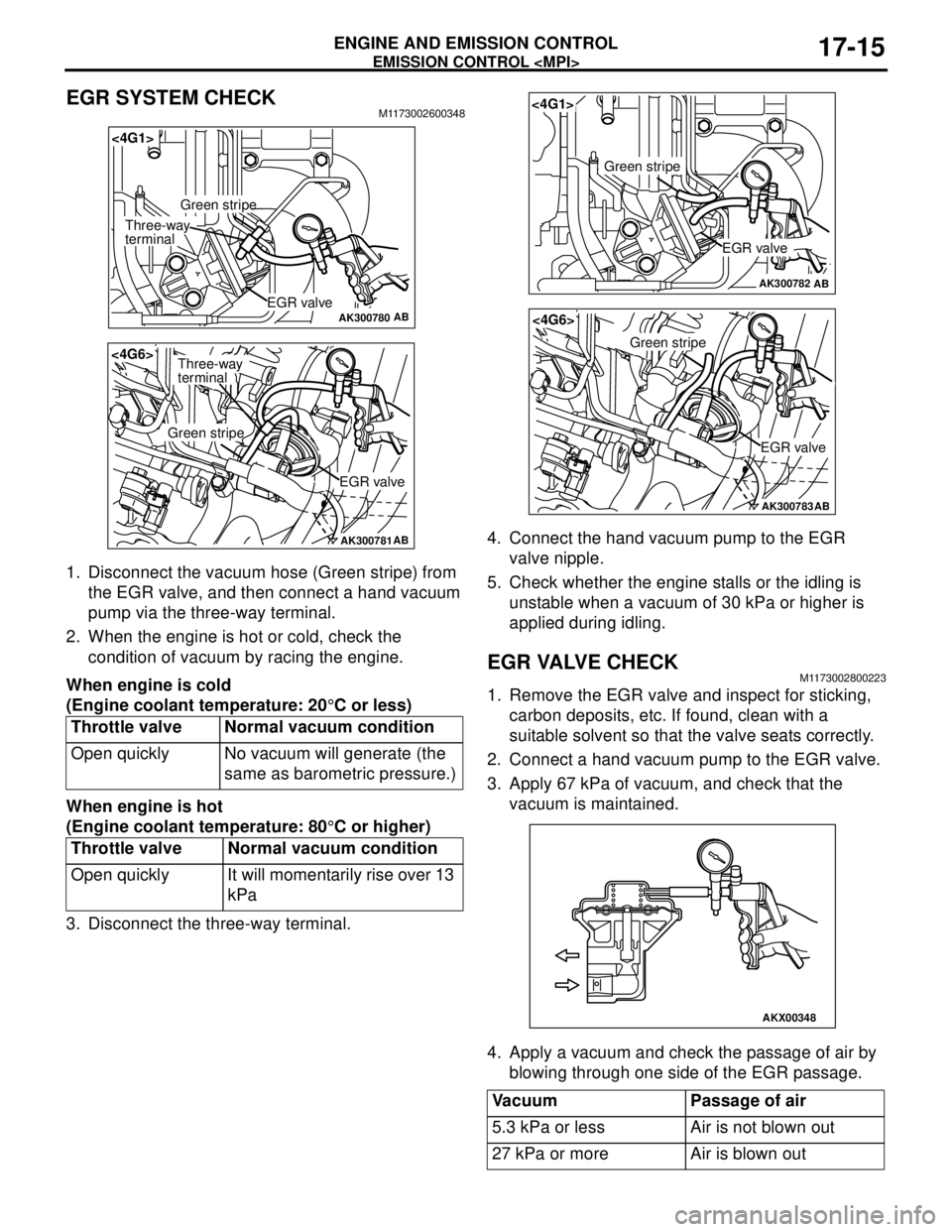
1. Disconnect the vacuum hose (Green stripe) from
the EGR valve, and then connect a hand vacuum
pump via the three-way terminal.
2. When the engine is hot or cold, check the
condition of vacuum by racing the engine.
When engine is cold
(Engine coolant temperature: 20°C or less)
When engine is hot
(Engine coolant temperature: 80°C or higher)
3. Disconnect the three-way terminal.4. Connect the hand vacuum pump to the EGR
valve nipple.
5. Check whether the engine stalls or the idling is
unstable when a vacuum of 30 kPa or higher is
applied during idling.
EGR VALVE CHECKM1173002800223
1. Remove the EGR valve and inspect for sticking,
carbon deposits, etc. If found, clean with a
suitable solvent so that the valve seats correctly.
2. Connect a hand vacuum pump to the EGR valve.
3. Apply 67 kPa of vacuum, and check that the
vacuum is maintained.
4. Apply a vacuum and check the passage of air by
blowing through one side of the EGR passage. Throttle valve Normal vacuum condition
Open quickly No vacuum will generate (the
same as barometric pressure.)
Throttle valve Normal vacuum condition
Open quickly It will momentarily rise over 13
kPa
AK300780AB
<4G1>
EGR valve
Green stripe
Three-way
terminal
AK300781AB
<4G6>
EGR valve
Green stripe
Three-way
terminal
Vacuum Passage of air
5.3 kPa or less Air is not blown out
27 kPa or more Air is blown out
AK300782AB
<4G1>
EGR valve
Green stripe
AK300783AB
<4G6>
EGR valve
Green stripe
AKX00348
Page 137 of 788
SPECIAL TOOLS
FRONT AXLE26-5
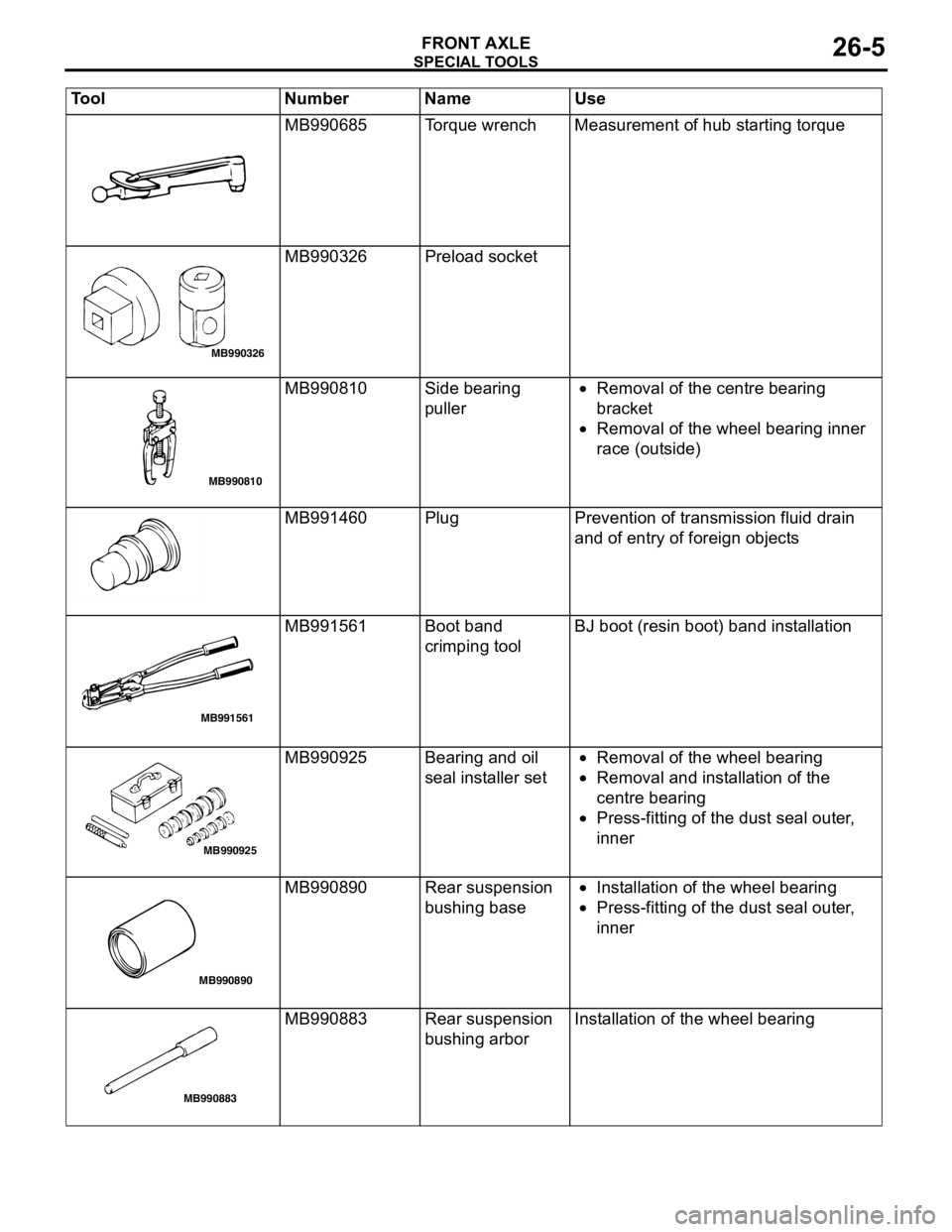
MB990685 Torque wrench Measurement of hub starting torque
MB990326 Preload socket
MB990810 Side bearing
puller•Removal of the centre bearing
bracket
•Removal of the wheel bearing inner
race (outside)
MB991460 Plug Prevention of transmission fluid drain
and of entry of foreign objects
MB991561 Boot band
crimping toolBJ boot (resin boot) band installation
MB990925 Bearing and oil
seal installer set•Removal of the wheel bearing
•Removal and installation of the
centre bearing
•Press-fitting of the dust seal outer,
inner
MB990890 Rear suspension
bushing base•Installation of the wheel bearing
•Press-fitting of the dust seal outer,
inner
MB990883 Rear suspension
bushing arborInstallation of the wheel bearing Tool Number Name Use
MB990326
MB990810
MB991561
MB990925
MB990890
MB990883
Page 144 of 788
Page 151 of 788
Page 152 of 788
DRIVE SHAFT ASSEMBLY
FRONT AXLE26-20
REASSEMBLY SERVICE POINTS
>>A<< DYNAMIC DAMPER/DAMPER
BAND/TJ BOOT INSTALLATION
CAUTION
There should be no grease adhered to the rubber
part of the dynamic damper.
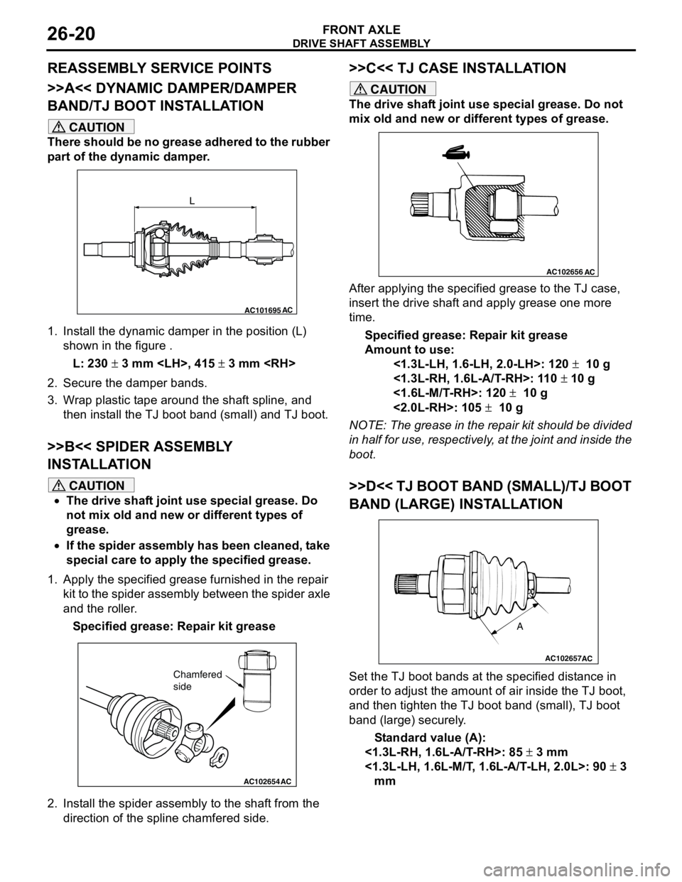
1. Install the dynamic damper in the position (L)
shown in the figure .
L: 230 ± 3 mm
2. Secure the damper bands.
3. Wrap plastic tape around the shaft spline, and
then install the TJ boot band (small) and TJ boot.
>>B<< SPIDER ASSEMBLY
INSTALLATION
CAUTION
•The drive shaft joint use special grease. Do
not mix old and new or different types of
grease.
•If the spider assembly has been cleaned, take
special care to apply the specified grease.
1. Apply the specified grease furnished in the repair
kit to the spider assembly between the spider axle
and the roller.
Specified grease: Repair kit grease
2. Install the spider assembly to the shaft from the
direction of the spline chamfered side.
>>C<< TJ CASE INSTALLATION
CAUTION
The drive shaft joint use special grease. Do not
mix old and new or different types of grease.
After applying the specified grease to the TJ case,
insert the drive shaft and apply grease one more
time.
Specified grease: Repair kit grease
Amount to use:
<1.3L-LH, 1.6-LH, 2.0-LH>: 120 ± 10 g
<1.3L-RH, 1.6L-A/T-RH>: 110 ± 10 g
<1.6L-M/T-RH>: 120 ± 10 g
<2.0L-RH>: 105 ± 10 g
NOTE: The grease in the repair kit should be divided
in half for use, respectively, at the joint and inside the
boot.
>>D<< TJ BOOT BAND (SMALL)/TJ BOOT
BAND (LARGE) INSTALLATION
Set the TJ boot bands at the specified distance in
order to adjust the amount of air inside the TJ boot,
and then tighten the TJ boot band (small), TJ boot
band (large) securely.
Standard value (A):
<1.3L-RH, 1.6L-A/T-RH>: 85 ± 3 mm
<1.3L-LH, 1.6L-M/T, 1.6L-A/T-LH, 2.0L>: 90 ± 3
mm
AC101695AC
L
AC102654AC
Chamfered
side
AC102656AC
AC102657
A
AC
Page 153 of 788
DRIVE SHAFT ASSEMBLY
FRONT AXLE26-21
INSPECTIONM1261003800130
•Check the drive shaft for damage, bending or
corrosion.
•Check the drive shaft spline part for wear or
damage.
•Check the spider assembly for roller rotation,
wear or corrosion.
•Check the groove inside TJ case for wear or
corrosion.
•Check the dynamic damper for damage or
cracking.
•Check the boots for deterioration, damage or
cracking.
BJ BOOT (RESIN BOOT) REPLACEMENTM1261005200361
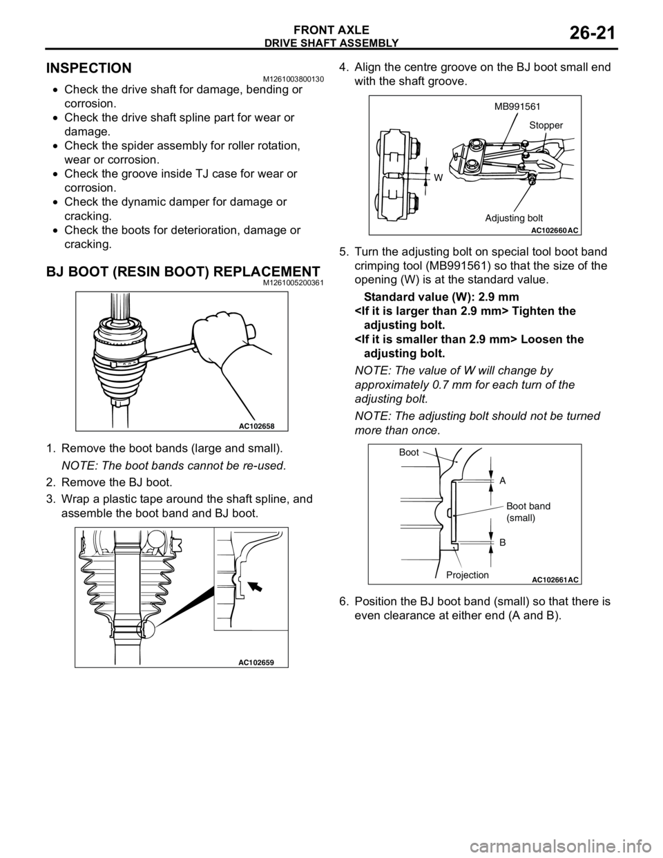
1. Remove the boot bands (large and small).
NOTE: The boot bands cannot be re-used.
2. Remove the BJ boot.
3. Wrap a plastic tape around the shaft spline, and
assemble the boot band and BJ boot.4. Align the centre groove on the BJ boot small end
with the shaft groove.
5. Turn the adjusting bolt on special tool boot band
crimping tool (MB991561) so that the size of the
opening (W) is at the standard value.
Standard value (W): 2.9 mm
adjusting bolt.
adjusting bolt.
NOTE: The value of W will change by
approximately 0.7 mm for each turn of the
adjusting bolt.
NOTE: The adjusting bolt should not be turned
more than once.
6. Position the BJ boot band (small) so that there is
even clearance at either end (A and B).
AC102658
AC102659
AC102660
WMB991561
Stopper
Adjusting bolt
AC
AC102661AC
Boot
A
Boot band
(small)
B
Projection