Side MITSUBISHI LANCER 2005 Owner's Guide
[x] Cancel search | Manufacturer: MITSUBISHI, Model Year: 2005, Model line: LANCER, Model: MITSUBISHI LANCER 2005Pages: 788, PDF Size: 45.98 MB
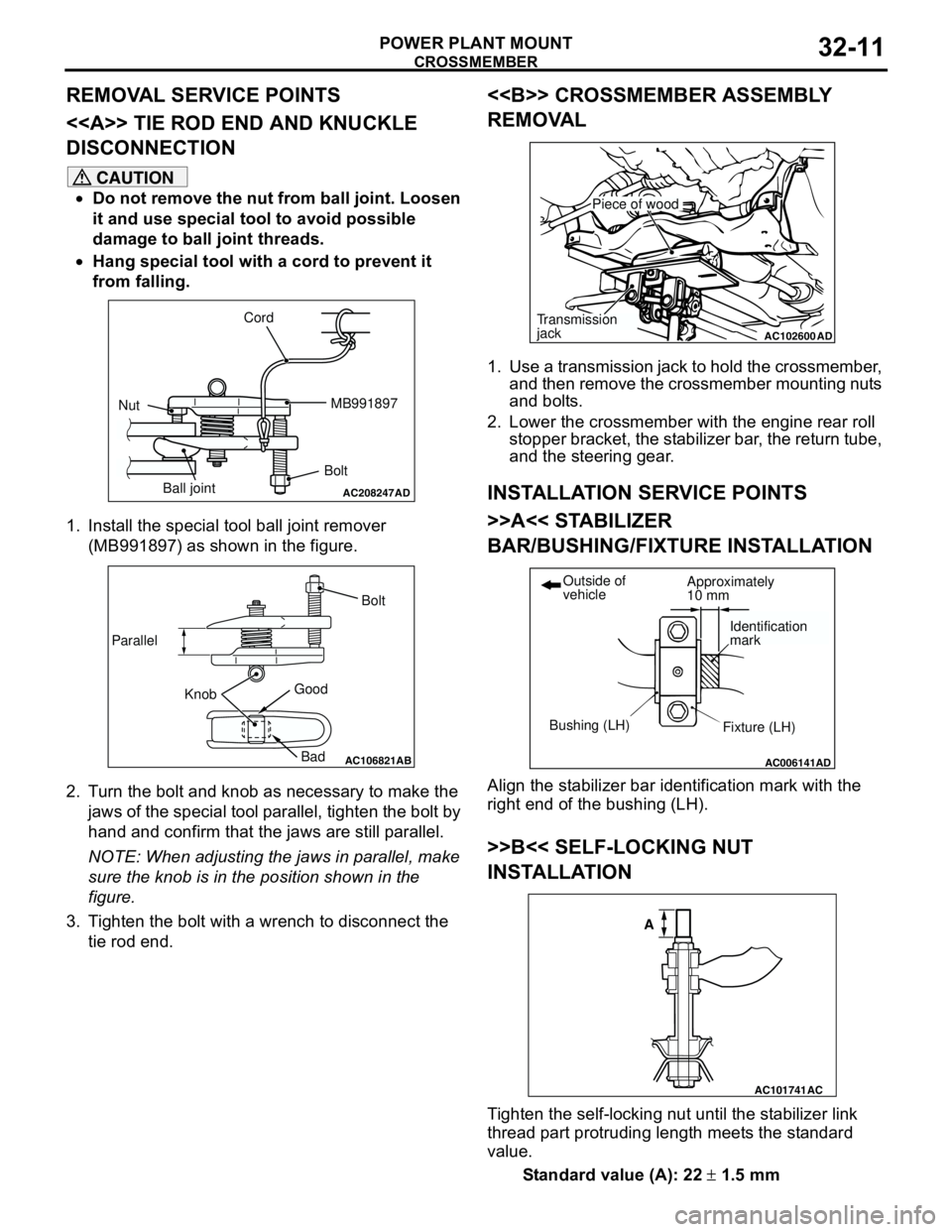
Page 154 of 788
DRIVE SHAFT ASSEMBLY
FRONT AXLE26-22
CAUTION
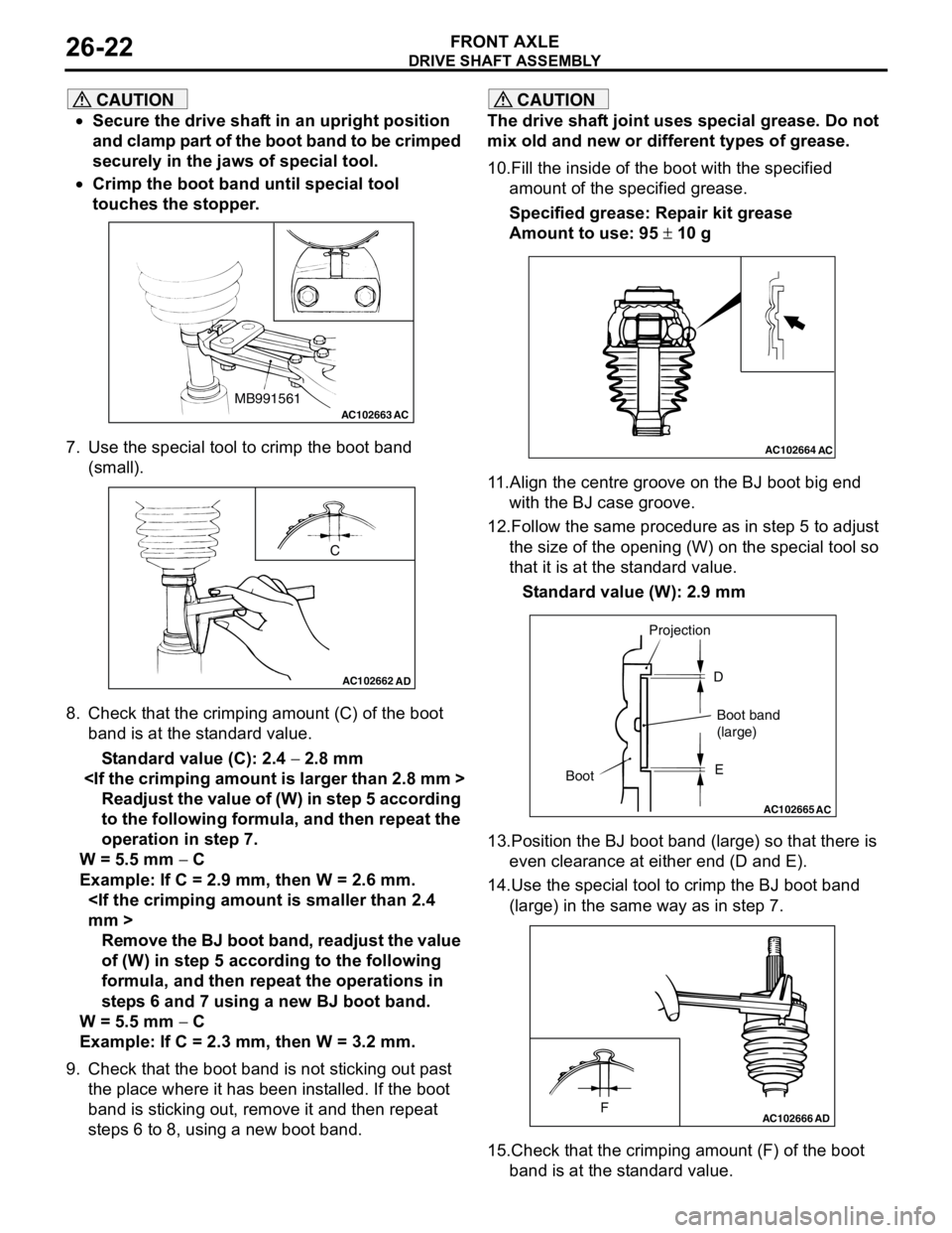
•Secure the drive shaft in an upright position
and clamp part of the boot band to be crimped
securely in the jaws of special tool.
•Crimp the boot band until special tool
touches the stopper.
7. Use the special tool to crimp the boot band
(small).
8. Check that the crimping amount (C) of the boot
band is at the standard value.
Standard value (C): 2.4 − 2.8 mm
Readjust the value of (W) in step 5 according
to the following formula, and then repeat the
operation in step 7.
W = 5.5 mm − C
Example: If C = 2.9 mm, then W = 2.6 mm.
Remove the BJ boot band, readjust the value
of (W) in step 5 according to the following
formula, and then repeat the operations in
steps 6 and 7 using a new BJ boot band.
W = 5.5 mm − C
Example: If C = 2.3 mm, then W = 3.2 mm.
9. Check that the boot band is not sticking out past
the place where it has been installed. If the boot
band is sticking out, remove it and then repeat
steps 6 to 8, using a new boot band.
CAUTION
The drive shaft joint uses special grease. Do not
mix old and new or different types of grease.
10.Fill the inside of the boot with the specified
amount of the specified grease.
Specified grease: Repair kit grease
Amount to use: 95 ± 10 g
11.Align the centre groove on the BJ boot big end
with the BJ case groove.
12.Follow the same procedure as in step 5 to adjust
the size of the opening (W) on the special tool so
that it is at the standard value.
Standard value (W): 2.9 mm
13.Position the BJ boot band (large) so that there is
even clearance at either end (D and E).
14.Use the special tool to crimp the BJ boot band
(large) in the same way as in step 7.
15.Check that the crimping amount (F) of the boot
band is at the standard value.
AC102663 ACMB991561
AC102662
C
AD
AC102664AC
AC102665
AC
BootProjection
Boot band
(large) D
E
AC102666FAD
Page 161 of 788
REAR AXLE HUB ASSEMBLY
REAR AXLE27-5
REAR AXLE HUB ASSEMBLY
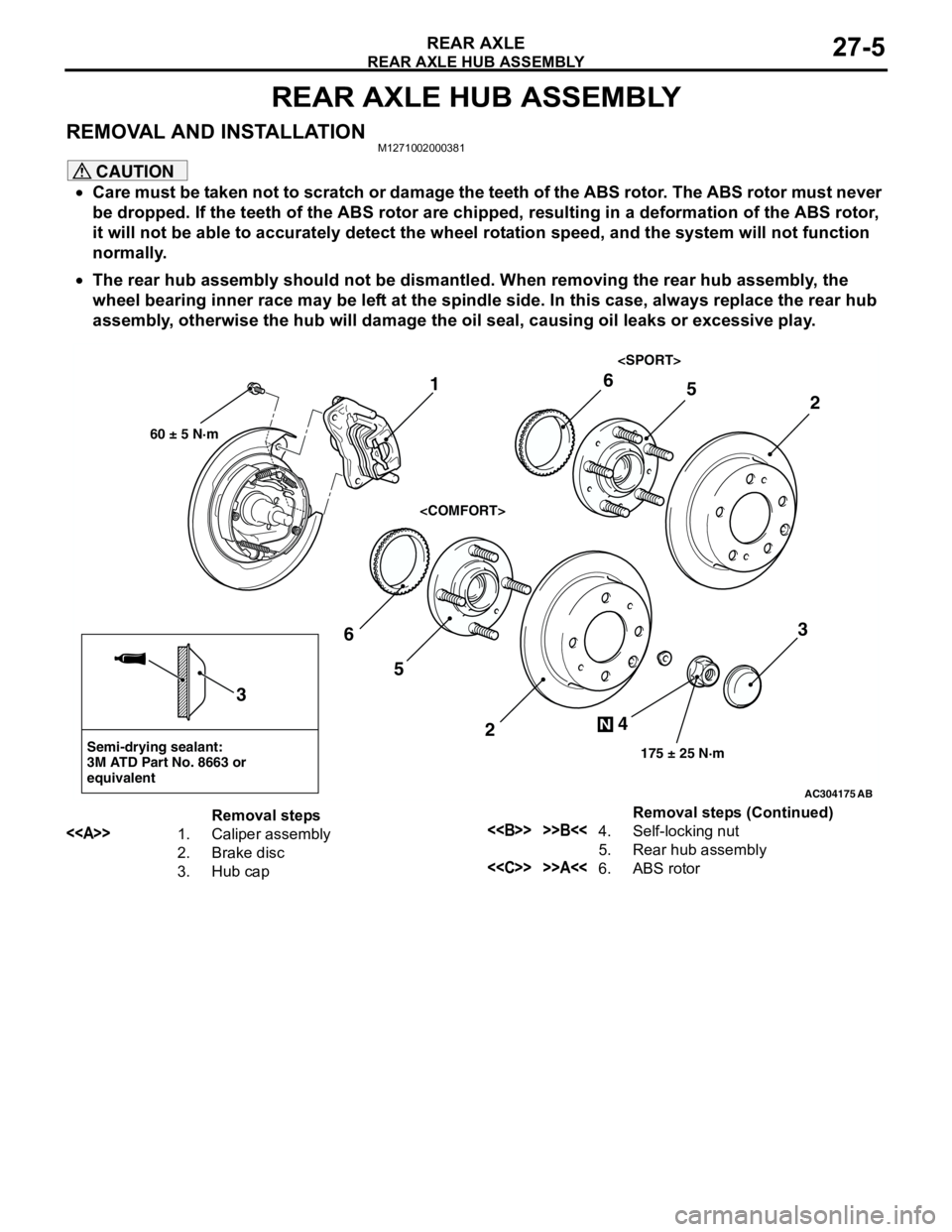
REMOVAL AND INSTALLATIONM1271002000381
CAUTION
•Care must be taken not to scratch or damage the teeth of the ABS rotor. The ABS rotor must never
be dropped. If the teeth of the ABS rotor are chipped, resulting in a deformation of the ABS rotor,
it will not be able to accurately detect the wheel rotation speed, and the system will not function
normally.
•The rear hub assembly should not be dismantled. When removing the rear hub assembly, the
wheel bearing inner race may be left at the spindle side. In this case, always replace the rear hub
assembly, otherwise the hub will damage the oil seal, causing oil leaks or excessive play.
AC304175
Semi-drying sealant:
3M ATD Part No. 8663 or
equivalent
2
3
5 6
4
N
175 ± 25 N·m
3
AB
1
60 ± 5 N·m
2
56
Removal steps
<>1. Caliper assembly
2. Brake disc
3. Hub cap<> >>B<<4. Self-locking nut
5. Rear hub assembly
<
Page 165 of 788
TROUBLESHOOTING
WHEEL AND TYRE31-3
TROUBLESHOOTING
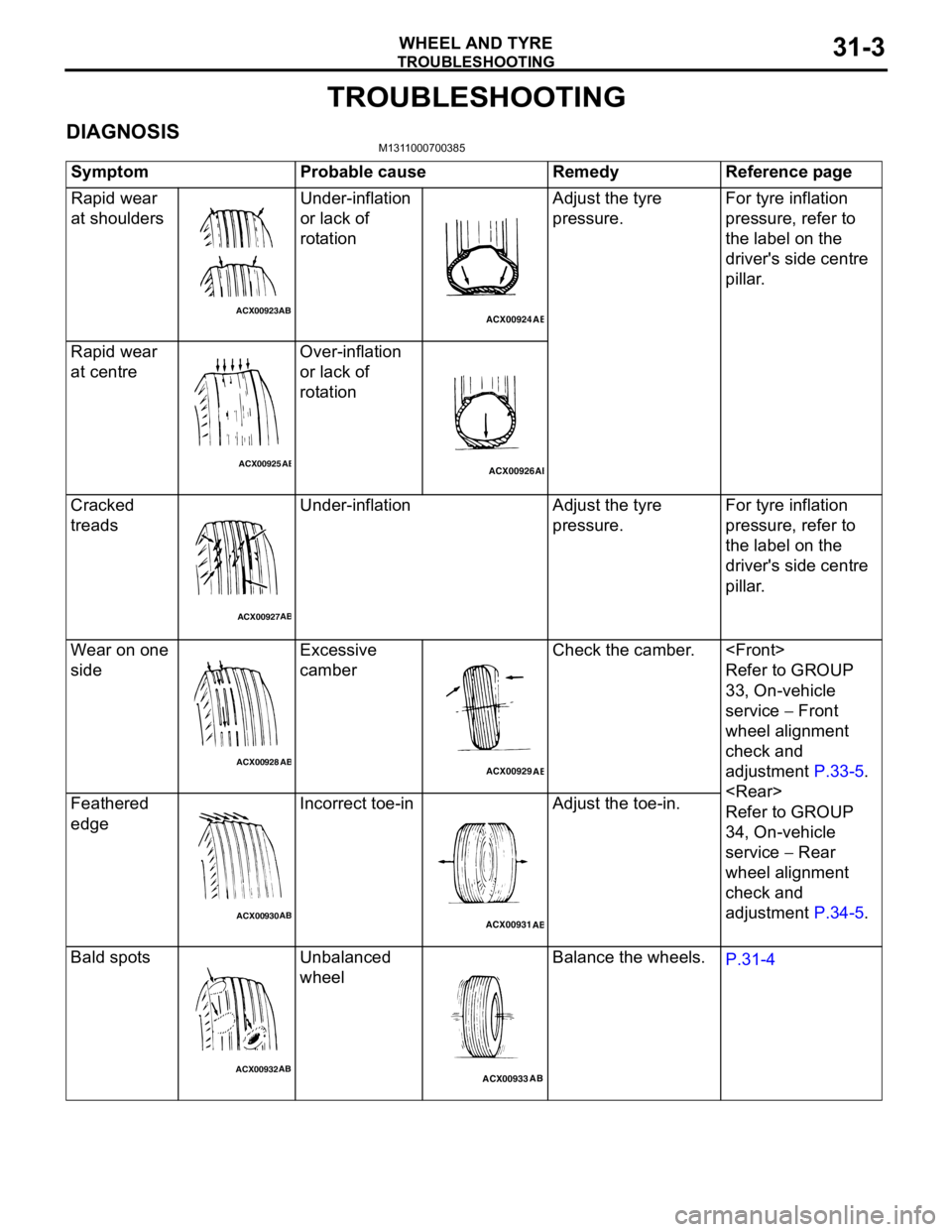
DIAGNOSISM1311000700385
Symptom Probable cause Remedy Reference page
Rapid wear
at shouldersUnder-inflation
or lack of
rotationAdjust the tyre
pressure.For tyre inflation
pressure, refer to
the label on the
driver's side centre
pillar.
Rapid wear
at centreOver-inflation
or lack of
rotation
Cracked
treadsUnder-inflation Adjust the tyre
pressure.For tyre inflation
pressure, refer to
the label on the
driver's side centre
pillar.
Wear on one
sideExcessive
camberCheck the camber.
Refer to GROUP
33, On-vehicle
service − Front
wheel alignment
check and
adjustment P.33-5.
Refer to GROUP
34, On-vehicle
service − Rear
wheel alignment
check and
adjustment P.34-5. Feathered
edgeIncorrect toe-in Adjust the toe-in.
Bald spots Unbalanced
wheelBalance the wheels.
P.31-4
ACX00923ABACX00924
AB
ACX00925ABACX00926AB
ACX00927AB
ACX00928
ABACX00929
AB
ACX00930ABACX00931
AB
ACX00932ABACX00933AB
Page 166 of 788
TROUBLESHOOTING
WHEEL AND TYRE31-4
WHEEL BALANCE ACCURACYM1311001700247
PURPOSE
This section contains tips and procedures for
achieving accurate wheel balance. Steering wheel
vibration and/or body shake can result if any of these
procedures are not carefully observed.
1. Wheels and tyres must be properly mounted on a
balancer in order to achieve correct balance.
Centring the wheel on the shaft of the balancer is
essential for proper mounting.
2. Off-the-car wheel balancers must be calibrated
periodically to ensure good balancing results. An
inaccurately calibrated balancer could cause
unnecessary replacement of tyres, shocks,
suspension components, or steering components.
Check your balancer's calibration approximately
every 100 balances. Your wheel balancer's
instruction manual should include calibration
procedures. If the calibration procedures specifically
for your balancer are missing, use the generic steps
in this section for zero calibration, static balance, and
dynamic balance checks. The wheel balancer
calibration checks are also described in the
flowchart. (Refer to P.31-6).
PROCEDURE
1. Confirm that the balancer's cone and the wheel
mounting cone are undamaged and free of dirt
and rust.
2. On this vehicle, the wheel's centre hole on the
hub side has a chamfered edge. Use a
back-mounting cone on your wheel balancer to
centre the wheel on the balancer shaft.
3. Install a wheel mounting cone. The appropriate
size cone for this vehicle is 67.0 mm.
4. Before balancing the wheel, remove any wheel
weights from both sides. Also check both sides for
any damage.
5. When installing wheel weights, hammer them at a
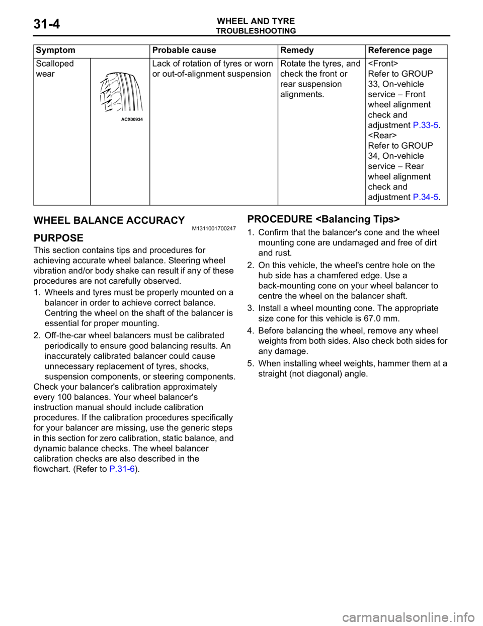
straight (not diagonal) angle. Scalloped
wearLack of rotation of tyres or worn
or out-of-alignment suspensionRotate the tyres, and
check the front or
rear suspension
alignments.
Refer to GROUP
33, On-vehicle
service − Front
wheel alignment
check and
adjustment P.33-5.
Refer to GROUP
34, On-vehicle
service − Rear
wheel alignment
check and
adjustment P.34-5. Symptom Probable cause Remedy Reference page
ACX00934
Page 169 of 788
ON-VEHICLE SERVICE
WHEEL AND TYRE31-7
ON-VEHICLE SERVICE
TYRE INFLATION PRESSURE CHECKM1311000900312
NOTE: For information on tyre inflation pressure,
refer to the label attached to the centre pillar on the
driver's side.
TYRE WEAR CHECKM1311001000334
Measure the tread depth of the tyres.
Minimum limit: 1.6 mm
If the remaining tread depth is less than the minimum
limit, replace the tyre.
NOTE: When the tread depth of the tyres is reduced
to 1.6 mm or less, wear indicators will appear.
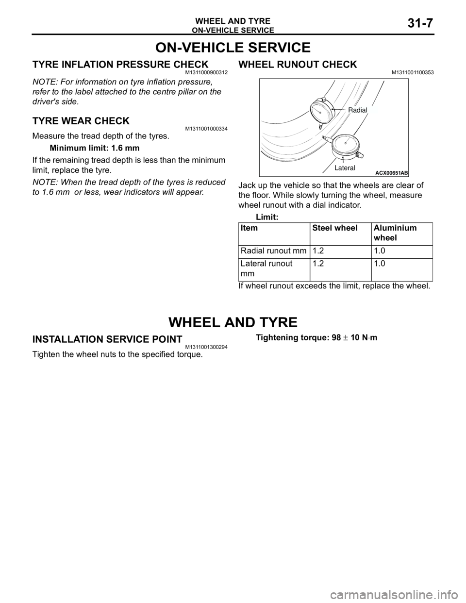
WHEEL RUNOUT CHECKM1311001100353
Jack up the vehicle so that the wheels are clear of
the floor. While slowly turning the wheel, measure
wheel runout with a dial indicator.
Limit:
If wheel runout exceeds the limit, replace the wheel.
WHEEL AND TYRE
INSTALLATION SERVICE POINTM1311001300294
Tighten the wheel nuts to the specified torque.Tightening torque: 98 ± 10 N⋅m Item Steel wheel Aluminium
wheel
Radial runout mm 1.2 1.0
Lateral runout
mm1.2 1.0
ACX00651
ABLateralRadial
Page 172 of 788
GENERAL INFORMATION
POWER PLANT MOUNT32-2
GENERAL INFORMATION
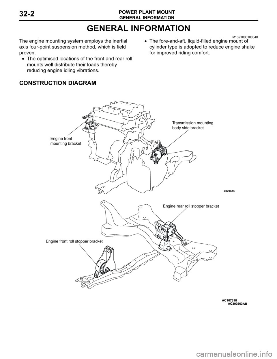
M1321000100340The engine mounting system employs the inertial
axis four-point suspension method, which is field
proven.
•The optimised locations of the front and rear roll
mounts well distribute their loads thereby
reducing engine idling vibrations.•The fore-and-aft, liquid-filled engine mount of
cylinder type is adopted to reduce engine shake
for improved riding comfort.
CONSTRUCTION DIAGRAM
AC107318
Y0290AU
AC303563
Engine front
mounting bracketTransmission mounting
body side bracket
Engine rear roll stopper bracket
Engine front roll stopper bracket
AB
Page 175 of 788
TRANSMISSION MOUNTING
POWER PLANT MOUNT32-5
TRANSMISSION MOUNTING
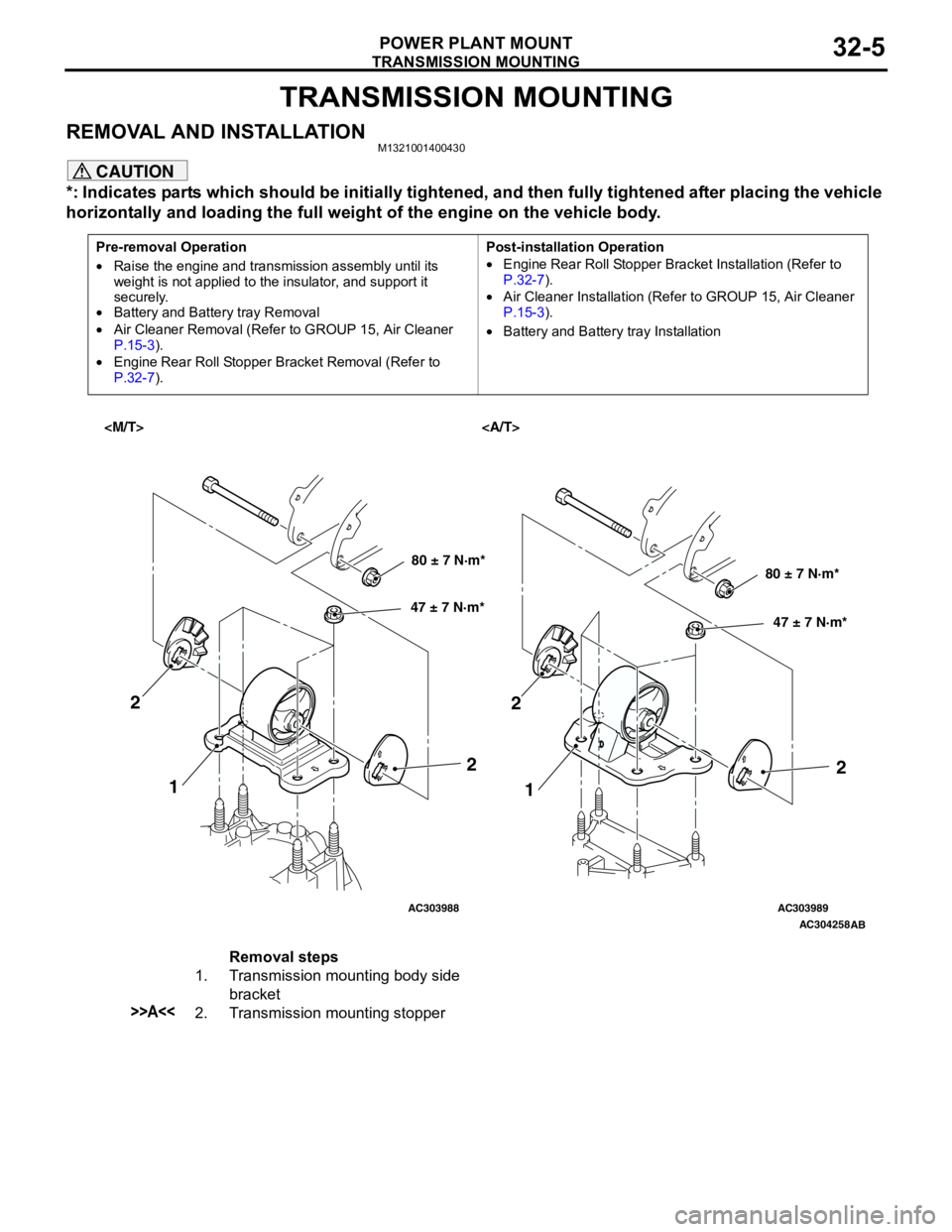
REMOVAL AND INSTALLATIONM1321001400430
CAUTION
*: Indicates parts which should be initially tightened, and then fully tightened after placing the vehicle
horizontally and loading the full weight of the engine on the vehicle body.
Pre-removal Operation
•Raise the engine and transmission assembly until its
weight is not applied to the insulator, and support it
securely.
•Battery and Battery tray Removal
•Air Cleaner Removal (Refer to GROUP 15, Air Cleaner
P.15-3).
•Engine Rear Roll Stopper Bracket Removal (Refer to
P.32-7).Post-installation Operation
•Engine Rear Roll Stopper Bracket Installation (Refer to
P.32-7).
•Air Cleaner Installation (Refer to GROUP 15, Air Cleaner
P.15-3).
•Battery and Battery tray Installation
AC303988AC303989
AC304258
AB
80 ± 7 N·m*
47 ± 7 N·m*80 ± 7 N·m*
47 ± 7 N·m*
1
1 2
22
2
Removal steps
1. Transmission mounting body side
bracket
>>A<<2. Transmission mounting stopper
Page 176 of 788
TRANSMISSION MOUNTING
POWER PLANT MOUNT32-6
INSTALLATION SERVICE POINT
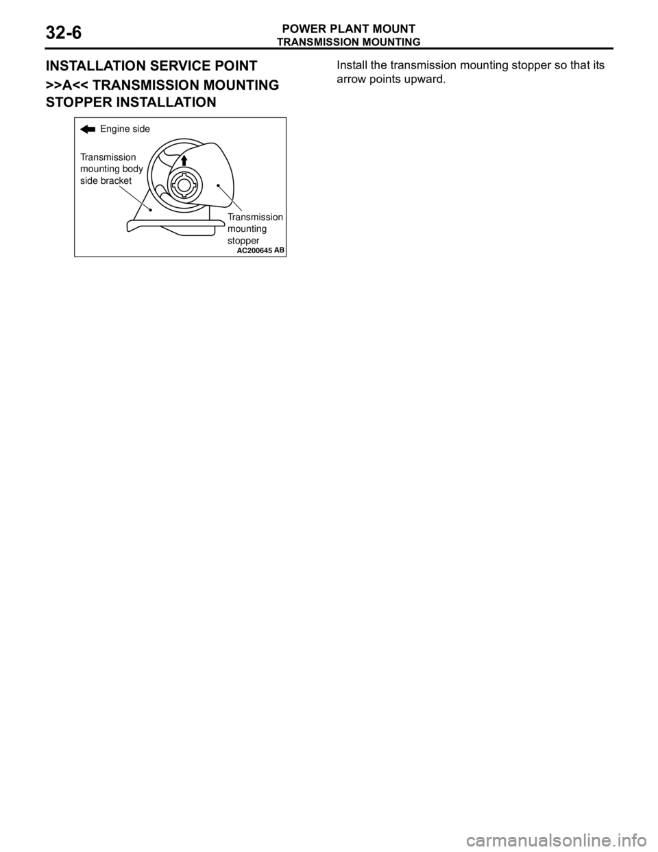
>>A<< TRANSMISSION MOUNTING
STOPPER INSTALLATIONInstall the transmission mounting stopper so that its
arrow points upward.
AC200645
Engine side
Transmission
mounting body
side bracket
Transmission
mounting
stopper
AB
Page 178 of 788
CROSSMEMBER
POWER PLANT MOUNT32-8
INSTALLATION SERVICE POINTS
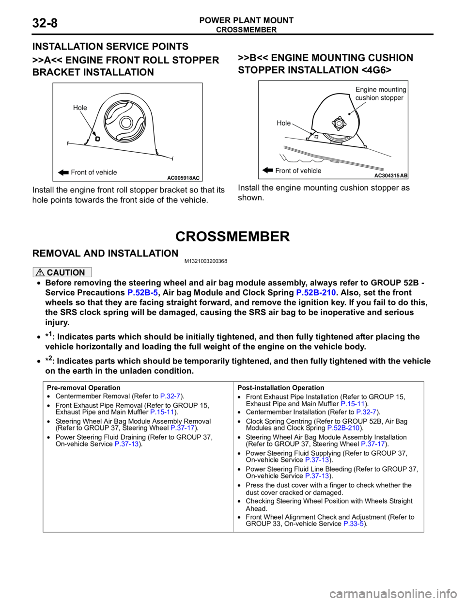
>>A<< ENGINE FRONT ROLL STOPPER
BRACKET INSTALLATION
Install the engine front roll stopper bracket so that its
hole points towards the front side of the vehicle.
>>B<< ENGINE MOUNTING CUSHION
STOPPER INSTALLATION <4G6>
Install the engine mounting cushion stopper as
shown.
CROSSMEMBER
REMOVAL AND INSTALLATIONM1321003200368
CAUTION
•Before removing the steering wheel and air bag module assembly, always refer to GROUP 52B -
Service Precautions P.52B-5, Air bag Module and Clock Spring P.52B-210. Also, set the front
wheels so that they are facing straight forward, and remove the ignition key. If you fail to do this,
the SRS clock spring will be damaged, causing the SRS air bag to be inoperative and serious
injury.
•*
1: Indicates parts which should be initially tightened, and then fully tightened after placing the
vehicle horizontally and loading the full weight of the engine on the vehicle body.
•*
2: Indicates parts which should be temporarily tightened, and then fully tightened with the vehicle
on the earth in the unladen condition.
AC005918Front of vehicleHoleACAC304315ABFront of vehicle
HoleEngine mounting
cushion stopper
Pre-removal Operation
•Centermember Removal (Refer to P.32-7).
•Front Exhaust Pipe Removal (Refer to GROUP 15,
Exhaust Pipe and Main Muffler P.15-11).
•Steering Wheel Air Bag Module Assembly Removal
(Refer to GROUP 37, Steering Wheel P.37-17).
•Power Steering Fluid Draining (Refer to GROUP 37,
On-vehicle Service P.37-13).Post-installation Operation
•Front Exhaust Pipe Installation (Refer to GROUP 15,
Exhaust Pipe and Main Muffler P.15-11).
•Centermember Installation (Refer to P.32-7).
•Clock Spring Centring (Refer to GROUP 52B, Air Bag
Modules and Clock Spring P.52B-210).
•Steering Wheel Air Bag Module Assembly Installation
(Refer to GROUP 37, Steering Wheel P.37-17).
•Power Steering Fluid Supplying (Refer to GROUP 37,
On-vehicle Service P.37-13).
•Power Steering Fluid Line Bleeding (Refer to GROUP 37,
On-vehicle Service P.37-13).
•Press the dust cover with a finger to check whether the
dust cover cracked or damaged.
•Checking Steering Wheel Position with Wheels Straight
Ahead.
•Front Wheel Alignment Check and Adjustment (Refer to
GROUP 33, On-vehicle Service P.33-5).
Page 181 of 788