Side MITSUBISHI LANCER 2005 Service Manual
[x] Cancel search | Manufacturer: MITSUBISHI, Model Year: 2005, Model line: LANCER, Model: MITSUBISHI LANCER 2005Pages: 788, PDF Size: 45.98 MB
Page 185 of 788

SERVICE SPECIFICATIONS
FRONT SUSPENSION33-3
SERVICE SPECIFICATIONS
M1332000300586
NOTE: *: difference between right and left wheels must be less than 30'
LUBRICANT
M1332000400152
ItemStandard value
Toe-in At the centre of tyre tread mm 1 ± 2
Toe-angle (per wheel) 0°03' ± 06'
Toe-out angle on turns (inner wheel when outer wheel at 20°)21°42' ± 1°30'
Steering angle Inner wheel Comfort 39°30' ± 1°30'
Sport (LH drive vehicles) 33°40' +1°00'/-2°00'
Sport (RH drive vehicles) 37°00' +1°00'/-2°00'
Outer wheel (reference) Comfort 32°30'
Sport (LH drive vehicles) 28°46'
Sport (RH drive vehicles) 30°00'
Camber Comfort 0°05' ± 30'*
Sport -0°05' ± 30'*
Caster Comfort 2°45' ± 30'*
Sport 2°55' ± 30'*
Kingpin inclination Comfort 12°30' ± 1°30'
Sport 12°40' ± 1°30'
Lower arm ball joint rotation starting torque N⋅m0 − 3.9
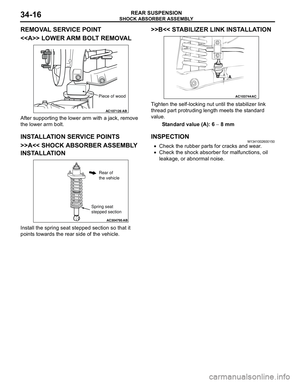
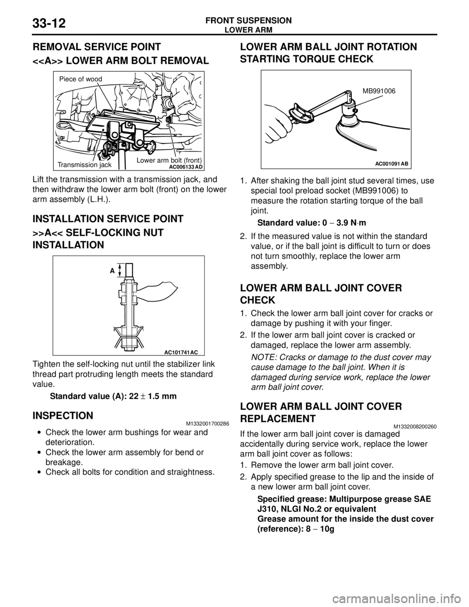
Protruding length of stabilizer link thread part mm 22 ± 1.5
Item Specified lubricant Quantity
Lower arm ball joint Lip portion of ball joint cover Multipurpose grease SAE J310,
NLGI No.2 or equivalentAs required
Inside of ball joint cover
Page 191 of 788
Page 194 of 788
Page 198 of 788
Page 203 of 788

SERVICE SPECIFICATIONS
REAR SUSPENSION34-3
SPECIFICATION
COIL SPRING
SERVICE SPECIFICATIONS
M1341000300409
LUBRICANT
M1341000400172
Item Sedan Wagon
Comfort Sport Comfort Sport
Wire diameter mm 10 10 10 10
Average diameter mm 78 − 90 78 − 90 78 − 90 78 − 90
Free length mm 359 331 377 368
Item Standard value
Camber (Difference between right and left within 30')
−0°40' ± 30'
Toe-in At the centre of tyre tread mm 3 ± 2
Toe-angle (per wheel) 0°08' ± 05'
Thrust angle 0°00' ± 0°09'
Control link pillow ball bushing rotation starting torque
Upper arm pillow ball bushing rotation starting torque
Lower arm pillow ball bushing rotation starting torque N⋅m0.5 − 3.0
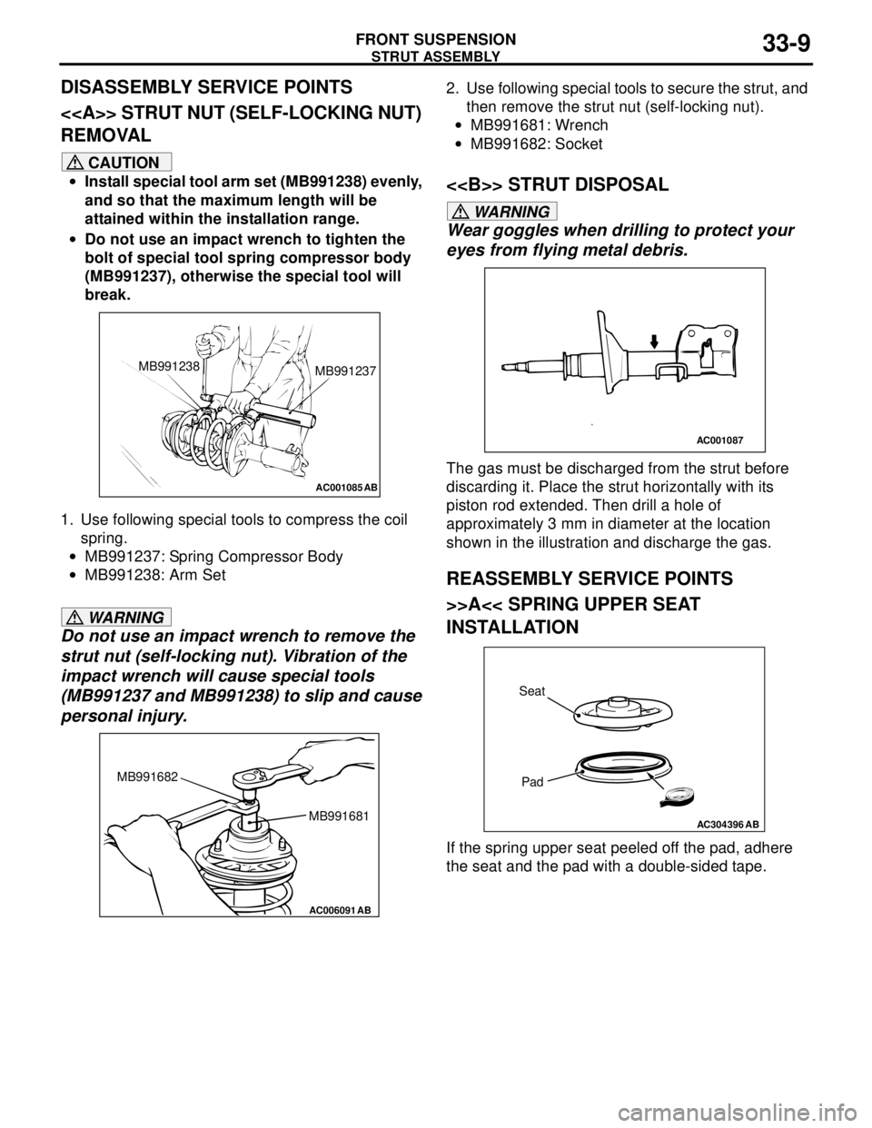
Protruding length of stabilizer link bolt mm 6 − 8
Stabilizer link ball joint continuous rotating torque N⋅m0.5 − 1.5
Item Specified lubricant Quantity
Stabilizer link ball joint (inside of dust cover) Multipurpose grease SAE J310, NLGI No.2
or equivalentAs required
Page 206 of 788
ON-VEHICLE SERVICE
REAR SUSPENSION34-6
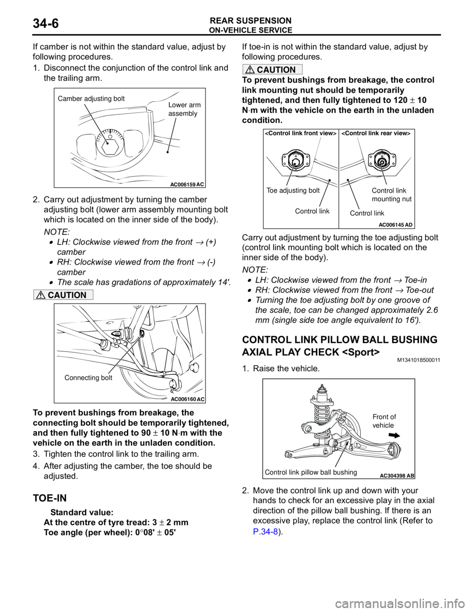
If camber is not within the standard value, adjust by
following procedures.
1. Disconnect the conjunction of the control link and
the trailing arm.
2. Carry out adjustment by turning the camber
adjusting bolt (lower arm assembly mounting bolt
which is located on the inner side of the body).
NOTE: .
•LH: Clockwise viewed from the front → (+)
camber
•RH: Clockwise viewed from the front → (-)
camber
•The scale has gradations of approximately 14'.
CAUTION
To prevent bushings from breakage, the
connecting bolt should be temporarily tightened,
and then fully tightened to 90 ± 10 N⋅m with the
vehicle on the earth in the unladen condition.
3. Tighten the control link to the trailing arm.
4. After adjusting the camber, the toe should be
adjusted.
TOE-IN
Standard value:
At the centre of tyre tread: 3 ± 2 mm
Toe angle (per wheel): 0°08' ± 05'If toe-in is not within the standard value, adjust by
following procedures.
CAUTION
To prevent bushings from breakage, the control
link mounting nut should be temporarily
tightened, and then fully tightened to 120 ± 10
N⋅m with the vehicle on the earth in the unladen
condition.
Carry out adjustment by turning the toe adjusting bolt
(control link mounting bolt which is located on the
inner side of the body).
NOTE: .
•LH: Clockwise viewed from the front → Toe-in
•RH: Clockwise viewed from the front → Toe-out
•Turning the toe adjusting bolt by one groove of
the scale, toe can be changed approximately 2.6
mm (single side toe angle equivalent to 16').
CONTROL LINK PILLOW BALL BUSHING
AXIAL PLAY CHECK
M1341018500011
1. Raise the vehicle.
2. Move the control link up and down with your
hands to check for an excessive play in the axial
direction of the pillow ball bushing. If there is an
excessive play, replace the control link (Refer to
P.34-8).
AC006159AC
Camber adjusting bolt
Lower arm
assembly
AC006160
AC
Connecting bolt
AC006145AD
Control link Toe adjusting boltControl link
Control link
mounting nut
AC304398ABControl link pillow ball bushing
Front of
vehicle
Page 209 of 788
Page 210 of 788
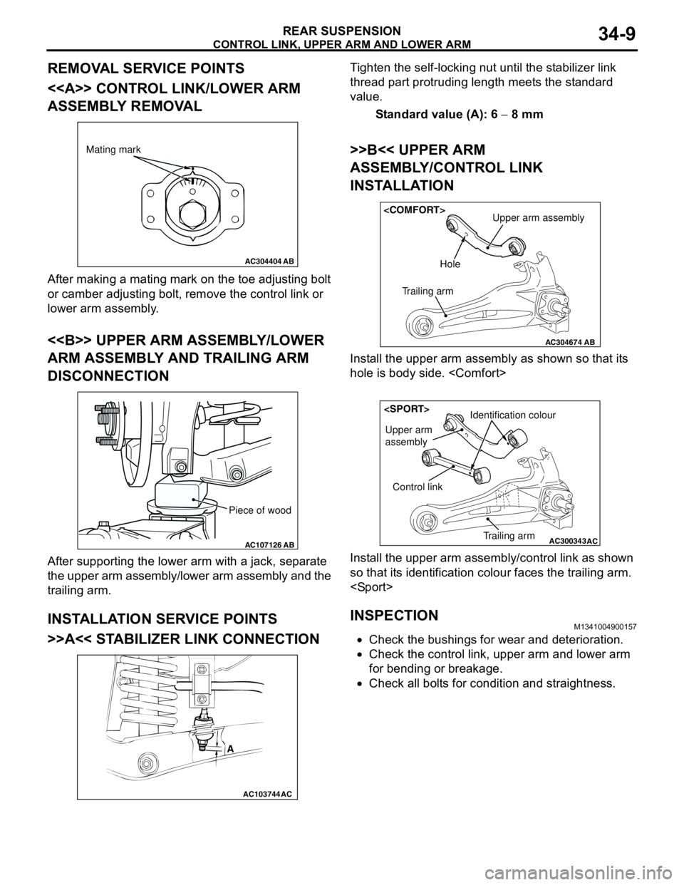
CONTROL LINK, UPPER ARM AND LOWER ARM
REAR SUSPENSION34-10
CONTROL LINK
BUSHING ROTATION STARTING TORQUE
CHECK
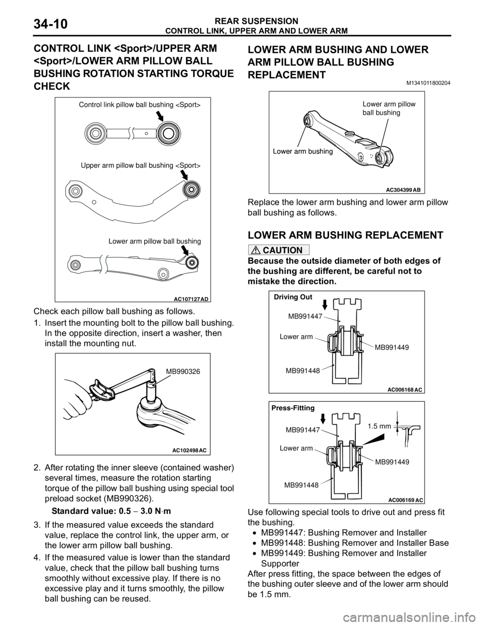
Check each pillow ball bushing as follows.
1. Insert the mounting bolt to the pillow ball bushing.
In the opposite direction, insert a washer, then
install the mounting nut.
2. After rotating the inner sleeve (contained washer)
several times, measure the rotation starting
torque of the pillow ball bushing using special tool
preload socket (MB990326).
Standard value: 0.5 − 3.0 N⋅m
3. If the measured value exceeds the standard
value, replace the control link, the upper arm, or
the lower arm pillow ball bushing.
4. If the measured value is lower than the standard
value, check that the pillow ball bushing turns
smoothly without excessive play. If there is no
excessive play and it turns smoothly, the pillow
ball bushing can be reused.
LOWER ARM BUSHING AND LOWER
ARM PILLOW BALL BUSHING
REPLACEMENT
M1341011800204
Replace the lower arm bushing and lower arm pillow
ball bushing as follows.
LOWER ARM BUSHING REPLACEMENT
CAUTION
Because the outside diameter of both edges of
the bushing are different, be careful not to
mistake the direction.
Use following special tools to drive out and press fit
the bushing.
•MB991447: Bushing Remover and Installer
•MB991448: Bushing Remover and Installer Base
•MB991449: Bushing Remover and Installer
Supporter
After press fitting, the space between the edges of
the bushing outer sleeve and of the lower arm should
be 1.5 mm.
AC107127AD
Lower arm pillow ball bushing Upper arm pillow ball bushing
AC102498
AC
MB990326
AC304399AB
Lower arm bushingLower arm pillow
ball bushing
Lower arm bushing
AC006168
AC
Driving Out
MB991447
Lower arm
MB991448MB991449
AC006169
AC
1.5 mm Press-Fitting
MB991447
Lower arm
MB991448MB991449
Page 214 of 788
TRAILING ARM ASSEMBLY
REAR SUSPENSION34-14
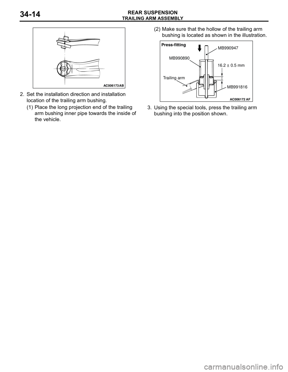
2. Set the installation direction and installation
location of the trailing arm bushing.
(1) Place the long projection end of the trailing
arm bushing inner pipe towards the inside of
the vehicle.(2) Make sure that the hollow of the trailing arm
bushing is located as shown in the illustration.
3. Using the special tools, press the trailing arm
bushing into the position shown.
AC006173 AB
AC006172AF
Press-fitting
MB990890
Trailing armMB990947
MB991816 16.2 ± 0.5 mm
Page 216 of 788