Side MITSUBISHI LANCER 2005 User Guide
[x] Cancel search | Manufacturer: MITSUBISHI, Model Year: 2005, Model line: LANCER, Model: MITSUBISHI LANCER 2005Pages: 788, PDF Size: 45.98 MB
Page 33 of 788
TROUBLESHOOTING
ENGINE COOLING14-19
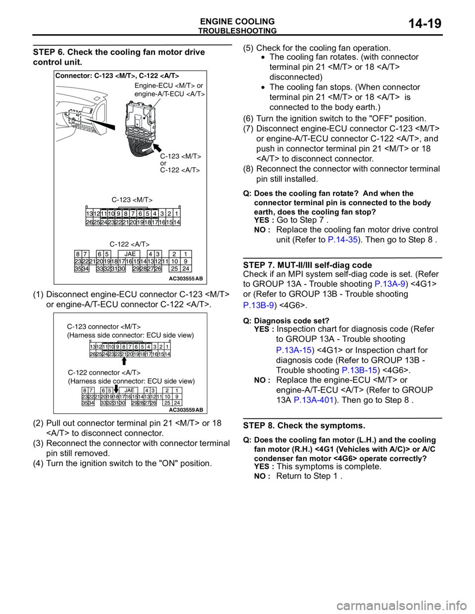
STEP 6. Check the cooling fan motor drive
control unit.
(1) Disconnect engine-ECU connector C-123
or engine-A/T-ECU connector C-122 .
(2) Pull out connector terminal pin 21
to disconnect connector.
(3) Reconnect the connector with connector terminal
pin still removed.
(4) Turn the ignition switch to the "ON" position.(5) Check for the cooling fan operation.
•The cooling fan rotates. (with connector
terminal pin 21
disconnected)
•The cooling fan stops. (When connector
terminal pin 21
connected to the body earth.)
(6) Turn the ignition switch to the "OFF" position.
(7) Disconnect engine-ECU connector C-123
or engine-A/T-ECU connector C-122 , and
push in connector terminal pin 21
to disconnect connector.
(8) Reconnect the connector with connector terminal
pin still installed.
Q: Does the cooling fan rotate? And when the
connector terminal pin is connected to the body
earth, does the cooling fan stop?
YES :
Go to Step 7 .
NO : Replace the cooling fan motor drive control
unit (Refer to P.14-35). Then go to Step 8 .
STEP 7. MUT-II/III self-diag code
Check if an MPI system self-diag code is set. (Refer
to GROUP 13A - Trouble shooting P.13A-9) <4G1>
or (Refer to GROUP 13B - Trouble shooting
P.13B-9) <4G6>.
Q: Diagnosis code set?
YES :
Inspection chart for diagnosis code (Refer
to GROUP 13A - Trouble shooting
P.13A-15) <4G1> or Inspection chart for
diagnosis code (Refer to GROUP 13B -
Trouble shooting P.13B-15) <4G6>.
NO : Replace the engine-ECU
engine-A/T-ECU (Refer to GROUP
13A P.13A-401). Then go to Step 8 .
STEP 8. Check the symptoms.
Q: Does the cooling fan motor (L.H.) and the cooling
fan motor (R.H.) <4G1 (Vehicles with A/C)> or A/C
condenser fan motor <4G6> operate correctly?
YES :
This symptoms is complete.
NO : Return to Step 1 .
AC303555AB
Connector: C-123
C-123
or
C-122
C-123
Engine-ECU
engine-A/T-ECU
C-122
AC303559
C-122 connector
(Harness side connector: ECU side view)
AB
C-123 connector
(Harness side connector: ECU side view)
Page 36 of 788
ON-VEHICLE SERVICE
ENGINE COOLING14-22
ON-VEHICLE SERVICE
ENGINE COOLANT LEAK CHECKM1141001000300
WARNING
When pressure testing the cooling system,
slowly release cooling system pressure to
avoid getting burned by hot coolant.
CAUTION
•Be sure to completely clean away any
moisture from the places checked.
•When the tester is taken out, be careful not to
spill any coolant.
•Be careful when installing and removing the
tester and when testing not to deform the
filler neck of the radiator.
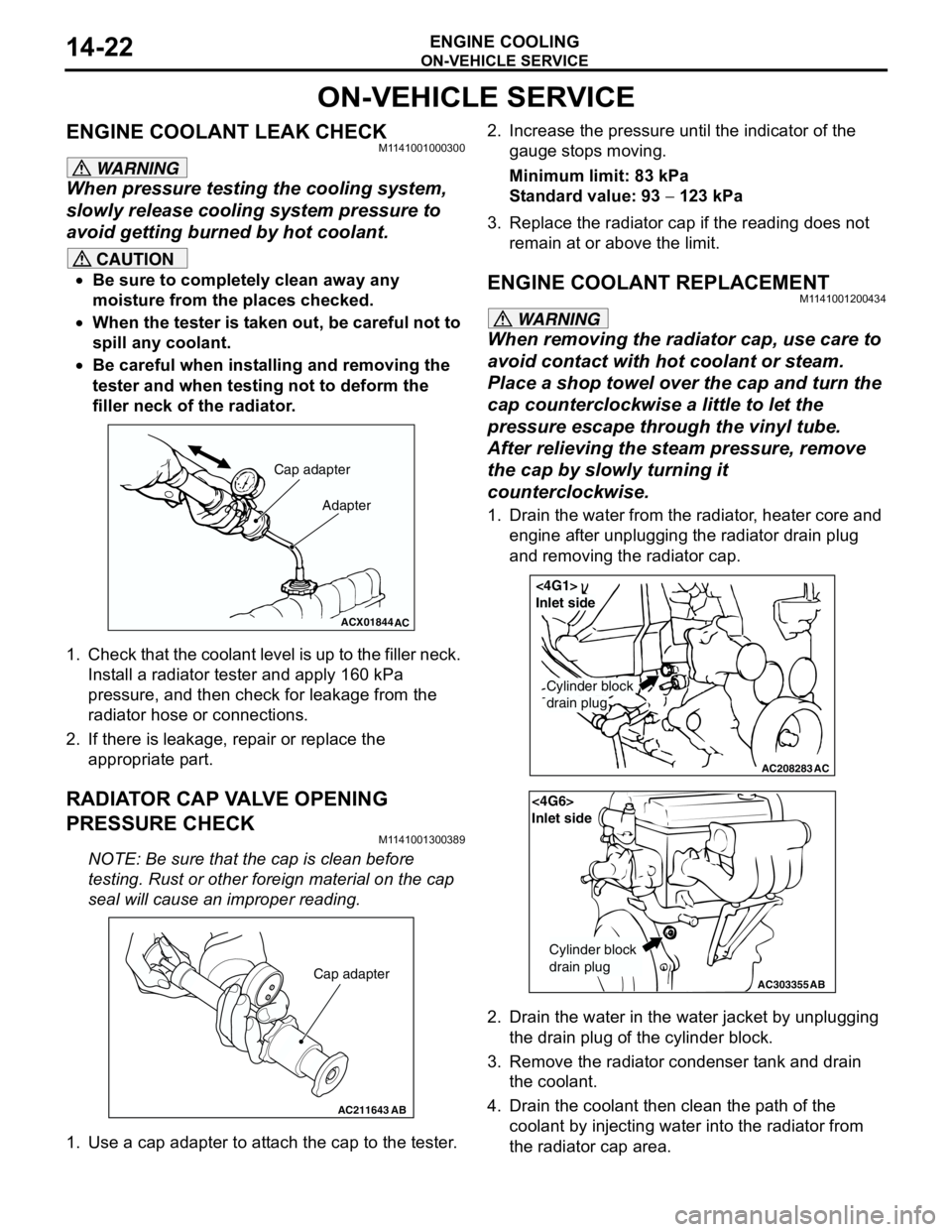
1. Check that the coolant level is up to the filler neck.
Install a radiator tester and apply 160 kPa
pressure, and then check for leakage from the
radiator hose or connections.
2. If there is leakage, repair or replace the
appropriate part.
RADIATOR CAP VALVE OPENING
PRESSURE CHECK
M1141001300389
NOTE: Be sure that the cap is clean before
testing. Rust or other foreign material on the cap
seal will cause an improper reading.
1. Use a cap adapter to attach the cap to the tester.2. Increase the pressure until the indicator of the
gauge stops moving.
Minimum limit: 83 kPa
Standard value: 93 − 123 kPa
3. Replace the radiator cap if the reading does not
remain at or above the limit.
ENGINE COOLANT REPLACEMENTM1141001200434
WARNING
When removing the radiator cap, use care to
avoid contact with hot coolant or steam.
Place a shop towel over the cap and turn the
cap counterclockwise a little to let the
pressure escape through the vinyl tube.
After relieving the steam pressure, remove
the cap by slowly turning it
counterclockwise.
1. Drain the water from the radiator, heater core and
engine after unplugging the radiator drain plug
and removing the radiator cap.
2. Drain the water in the water jacket by unplugging
the drain plug of the cylinder block.
3. Remove the radiator condenser tank and drain
the coolant.
4. Drain the coolant then clean the path of the
coolant by injecting water into the radiator from
the radiator cap area.
ACX01844
Cap adapter
Adapter
AC
AC211643AB
Cap adapter
AC208283AC
Cylinder block
drain plug
<4G1>
Inlet side
AC303355
<4G6>
Inlet side
Cylinder block
drain plug
AB
Page 37 of 788
ON-VEHICLE SERVICE
ENGINE COOLING14-23
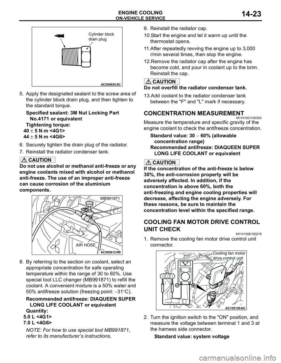
5. Apply the designated sealant to the screw area of
the cylinder block drain plug, and then tighten to
the standard torque.
Specified sealant: 3M Nut Locking Part
No.4171 or equivalent
Tightening torque:
40 ± 5 N⋅m <4G1>
44 ± 5 N⋅m <4G6>
6. Securely tighten the drain plug of the radiator.
7. Reinstall the radiator condenser tank.
CAUTION
Do not use alcohol or methanol anti-freeze or any
engine coolants mixed with alcohol or methanol
anti-freeze. The use of an improper anti-freeze
can cause corrosion of the aluminium
components.
8. By referring to the section on coolant, select an
appropriate concentration for safe operating
temperature within the range of 30 to 60%. Use
special tool LLC changer (MB991871) to refill the
coolant. A convenient mixture is a 50% water and
50% antifreeze solution (freezing point: −31°C).
Recommended antifreeze: DIAQUEEN SUPER
LONG LIFE COOLANT or equivalent
Quantity:
5.0 L <4G1>
7.0 L <4G6>
NOTE: For how to use special tool MB991871,
refer to its manufacturer’s instructions.9. Reinstall the radiator cap.
10.Start the engine and let it warm up until the
thermostat opens.
11.After repeatedly revving the engine up to 3,000
r/min several times, then stop the engine.
12.Remove the radiator cap after the engine has
become cold, and pour in coolant up to the brim.
Reinstall the cap.
CAUTION
Do not overfill the radiator condenser tank.
13.Add coolant to the radiator condenser tank
between the "F" and "L" mark if necessary.
CONCENTRATION MEASUREMENTM1141001100352
Measure the temperature and specific gravity of the
engine coolant to check the antifreeze concentration.
Standard value: 30 − 60% (allowable
concentration range)
Recommended antifreeze: DIAQUEEN SUPER
LONG LIFE COOLANT or equivalent
CAUTION
If the concentration of the anti-freeze is below
30%, the anti-corrosion property will be
adversely affected. In addition, if the
concentration is above 60%, both the
anti-freezing and engine cooling properties will
decrease, affecting the engine adversely. For
these reasons, be sure to maintain the
concentration level within the specified range.
COOLING FAN MOTOR DRIVE CONTROL
UNIT CHECK
M1141006100216
1. Remove the cooling fan motor drive control unit
connector.
2. Turn the ignition switch to the "ON" position, and
measure the voltage between terminal 1 and 3 at
the harness side connector.
Standard value: system voltage
AC200625
Cylinder block
drain plug
AC
AC303612AB
MB991871
AIR HOSE
AC103195
Y1716AU
1 23
AC
Cooling fan motor
drive control unit
Page 38 of 788
ON-VEHICLE SERVICE
ENGINE COOLING14-24
3. Connect the cooling fan motor drive control unit
connector, and disconnect the cooling fan motor
(L.H.) connector.
4. Ensure that the A/C switch is off, and start the
engine and run it at idle.
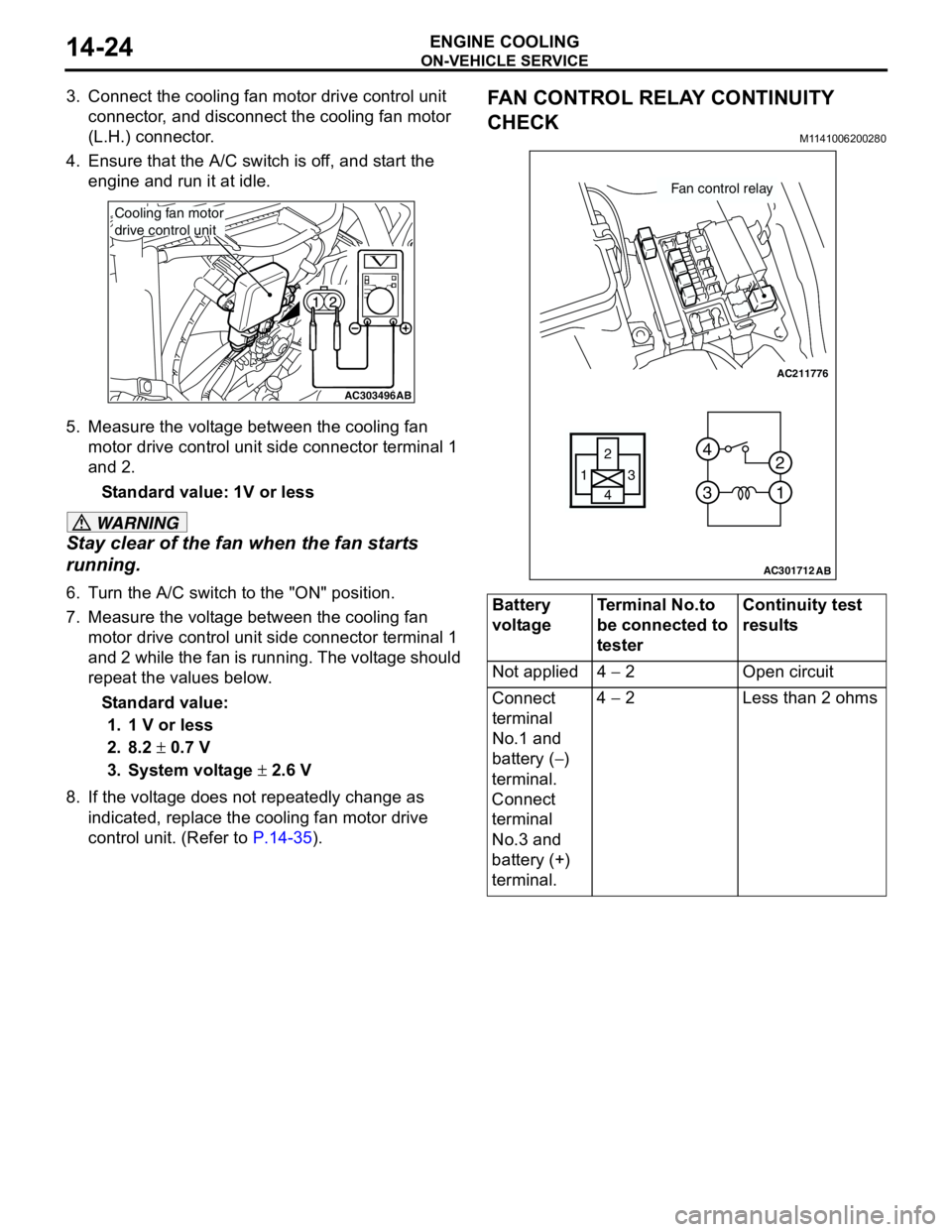
5. Measure the voltage between the cooling fan
motor drive control unit side connector terminal 1
and 2.
Standard value: 1V or less
WARNING
Stay clear of the fan when the fan starts
running.
6. Turn the A/C switch to the "ON" position.
7. Measure the voltage between the cooling fan
motor drive control unit side connector terminal 1
and 2 while the fan is running. The voltage should
repeat the values below.
Standard value:
1. 1 V or less
2. 8.2 ± 0.7 V
3. System voltage ± 2.6 V
8. If the voltage does not repeatedly change as
indicated, replace the cooling fan motor drive
control unit. (Refer to P.14-35).
FAN CONTROL RELAY CONTINUITY
CHECK
M1141006200280
AC303496AB
Cooling fan motor
drive control unit
Battery
voltageTerminal No.to
be connected to
testerContinuity test
results
Not applied 4 − 2 Open circuit
Connect
terminal
No.1 and
battery (−)
terminal.
Connect
terminal
No.3 and
battery (+)
terminal.4 − 2 Less than 2 ohms
AC211776
13
4 2
3 4
1 2
AC301712
Fan control relay
AB
Page 44 of 788
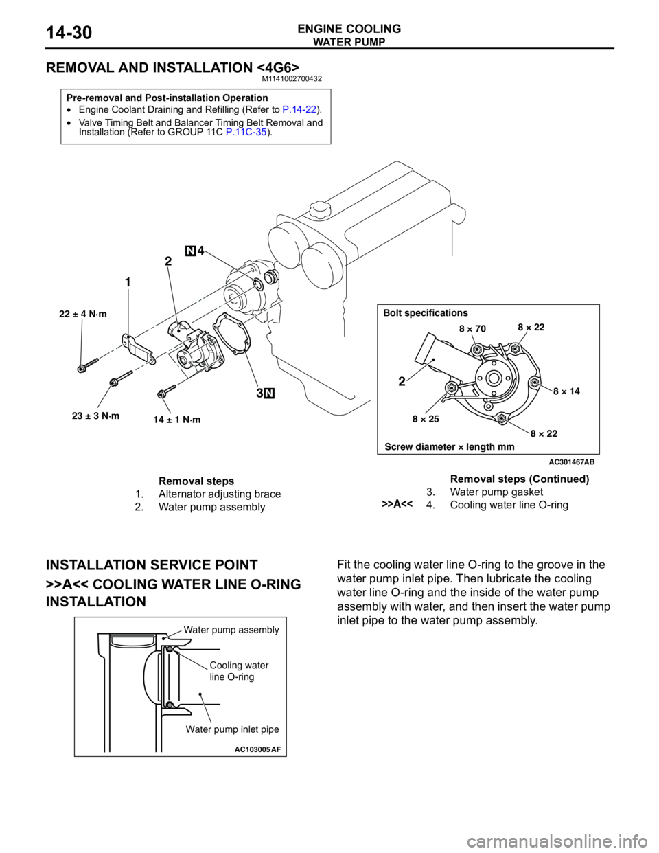
WAT E R P U M P
ENGINE COOLING14-30
REMOVAL AND INSTALLATION <4G6>M1141002700432
INSTALLATION SERVICE POINT
>>A<< COOLING WATER LINE O-RING
INSTALLATIONFit the cooling water line O-ring to the groove in the
water pump inlet pipe. Then lubricate the cooling
water line O-ring and the inside of the water pump
assembly with water, and then insert the water pump
inlet pipe to the water pump assembly.
Pre-removal and Post-installation Operation
•Engine Coolant Draining and Refilling (Refer to P.14-22).
•Valve Timing Belt and Balancer Timing Belt Removal and
Installation (Refer to GROUP 11C P.11C-35).
AC301467
22 ± 4 N·m
23 ± 3 N·m
14 ± 1 N·m
12
3 4
N
N
Bolt specifications
Screw diameter × length mm
8 × 708 × 22
8 × 14
8 × 22 8 × 25
2
AB
Removal steps
1. Alternator adjusting brace
2. Water pump assembly3. Water pump gasket
>>A<<4. Cooling water line O-ringRemoval steps (Continued)
AC103005
Water pump assembly
Cooling water
line O-ring
Water pump inlet pipe
AF
Page 78 of 788
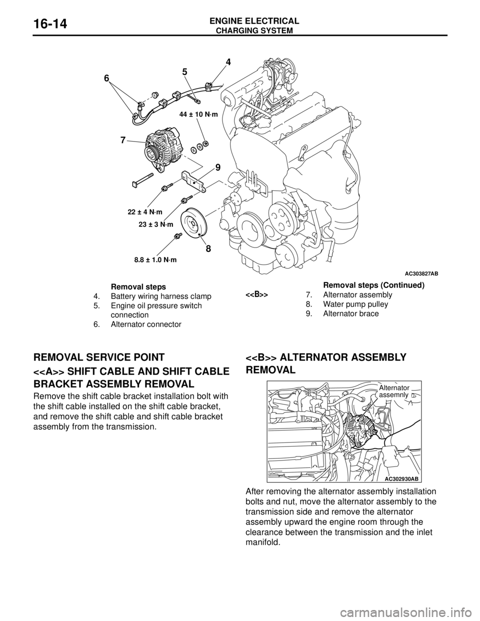
Page 82 of 788
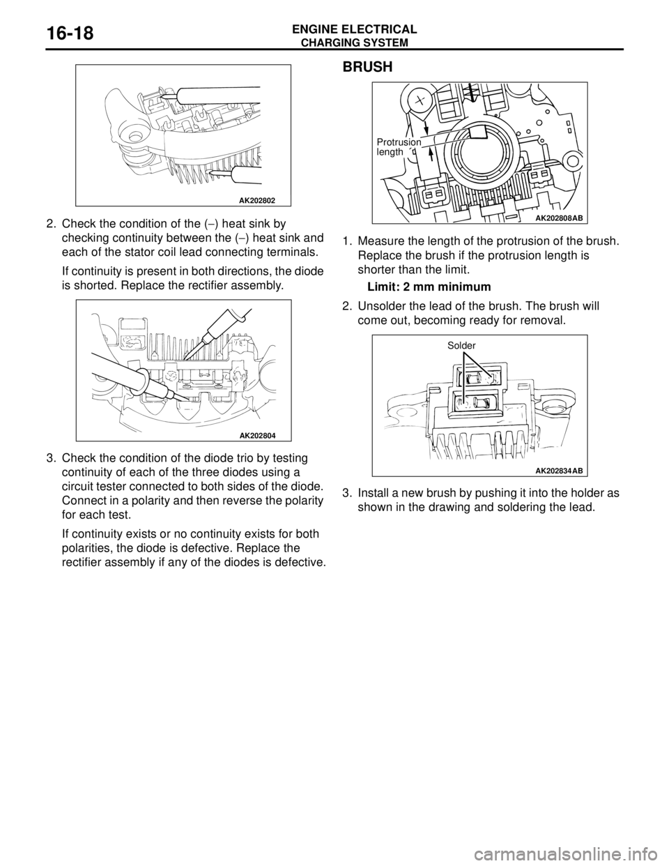
CHARGING SYSTEM
ENGINE ELECTRICAL16-18
2. Check the condition of the (−) heat sink by
checking continuity between the (−) heat sink and
each of the stator coil lead connecting terminals.
If continuity is present in both directions, the diode
is shorted. Replace the rectifier assembly.
3. Check the condition of the diode trio by testing
continuity of each of the three diodes using a
circuit tester connected to both sides of the diode.
Connect in a polarity and then reverse the polarity
for each test.
If continuity exists or no continuity exists for both
polarities, the diode is defective. Replace the
rectifier assembly if any of the diodes is defective.
BRUSH
1. Measure the length of the protrusion of the brush.
Replace the brush if the protrusion length is
shorter than the limit.
Limit: 2 mm minimum
2. Unsolder the lead of the brush. The brush will
come out, becoming ready for removal.
3. Install a new brush by pushing it into the holder as
shown in the drawing and soldering the lead.
AK202802
AK202804
AK202808
Protrusion
length
AB
AK202834
Solder
AB
Page 83 of 788
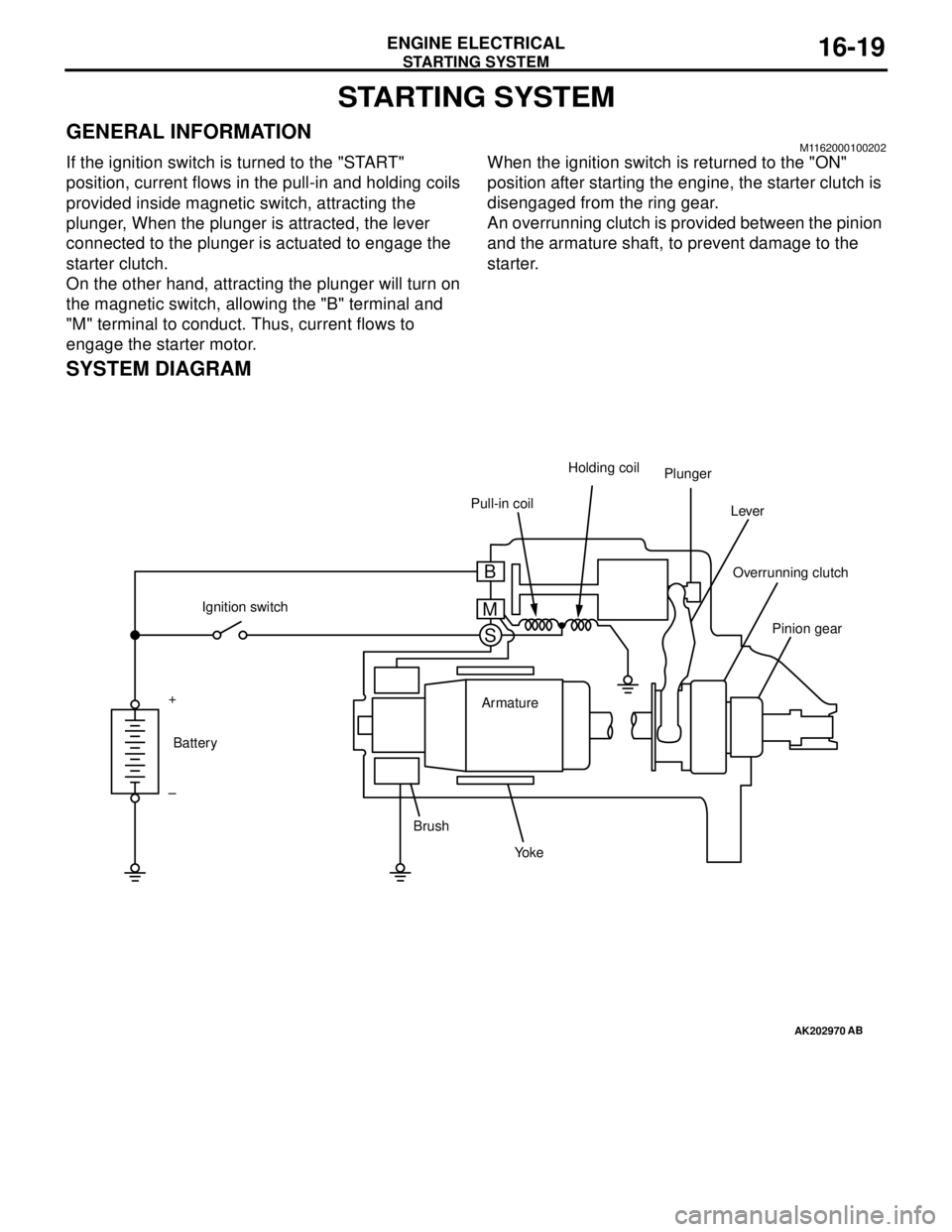
STARTING SYSTEM
ENGINE ELECTRICAL16-19
STARTING SYSTEM
GENERAL INFORMATIONM1162000100202
If the ignition switch is turned to the "START"
position, current flows in the pull-in and holding coils
provided inside magnetic switch, attracting the
plunger, When the plunger is attracted, the lever
connected to the plunger is actuated to engage the
starter clutch.
On the other hand, attracting the plunger will turn on
the magnetic switch, allowing the "B" terminal and
"M" terminal to conduct. Thus, current flows to
engage the starter motor.When the ignition switch is returned to the "ON"
position after starting the engine, the starter clutch is
disengaged from the ring gear.
An overrunning clutch is provided between the pinion
and the armature shaft, to prevent damage to the
starter.
SYSTEM DIAGRAM
AK202970
Pull-in coilHolding coil
Plunger
Lever
Pinion gear Overrunning clutch
Yo k e BrushArmature Ignition switch
Battery +
–
AB
B
M
S
Page 91 of 788
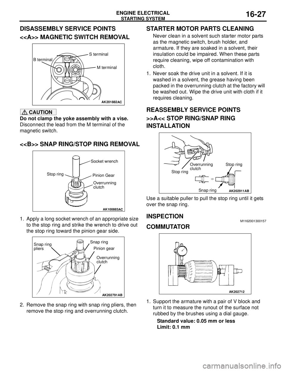
Page 94 of 788
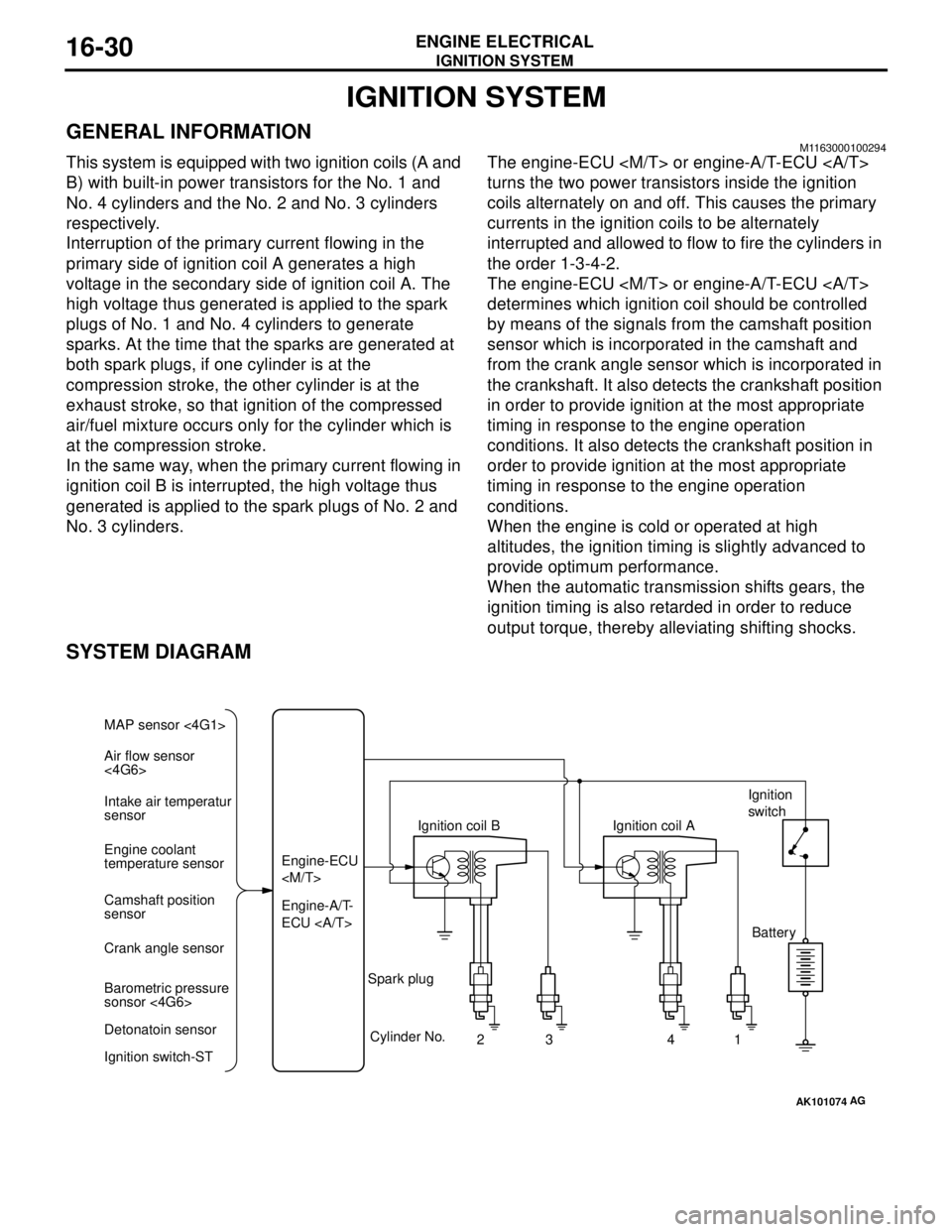
IGNITION SYSTEM
ENGINE ELECTRICAL16-30
IGNITION SYSTEM
GENERAL INFORMATIONM1163000100294
This system is equipped with two ignition coils (A and
B) with built-in power transistors for the No. 1 and
No. 4 cylinders and the No. 2 and No. 3 cylinders
respectively.
Interruption of the primary current flowing in the
primary side of ignition coil A generates a high
voltage in the secondary side of ignition coil A. The
high voltage thus generated is applied to the spark
plugs of No. 1 and No. 4 cylinders to generate
sparks. At the time that the sparks are generated at
both spark plugs, if one cylinder is at the
compression stroke, the other cylinder is at the
exhaust stroke, so that ignition of the compressed
air/fuel mixture occurs only for the cylinder which is
at the compression stroke.
In the same way, when the primary current flowing in
ignition coil B is interrupted, the high voltage thus
generated is applied to the spark plugs of No. 2 and
No. 3 cylinders.The engine-ECU
turns the two power transistors inside the ignition
coils alternately on and off. This causes the primary
currents in the ignition coils to be alternately
interrupted and allowed to flow to fire the cylinders in
the order 1-3-4-2.
The engine-ECU
determines which ignition coil should be controlled
by means of the signals from the camshaft position
sensor which is incorporated in the camshaft and
from the crank angle sensor which is incorporated in
the crankshaft. It also detects the crankshaft position
in order to provide ignition at the most appropriate
timing in response to the engine operation
conditions. It also detects the crankshaft position in
order to provide ignition at the most appropriate
timing in response to the engine operation
conditions.
When the engine is cold or operated at high
altitudes, the ignition timing is slightly advanced to
provide optimum performance.
When the automatic transmission shifts gears, the
ignition timing is also retarded in order to reduce
output torque, thereby alleviating shifting shocks.
SYSTEM DIAGRAM
AK101074
Air flow sensor
<4G6> MAP sensor <4G1>
Intake air temperatur
sensor
Engine coolant
temperature sensor
Camshaft position
sensor
Crank angle sensor
Barometric pressure
sonsor <4G6>
Detonatoin sensor
Ignition switch-STEngine-A/T-
ECU Engine-ECU
Cylinder No.
23 4
AG
1 Spark plugIgnition coil AIgnition
switch
Battery