front MITSUBISHI LANCER 2005 Owners Manual
[x] Cancel search | Manufacturer: MITSUBISHI, Model Year: 2005, Model line: LANCER, Model: MITSUBISHI LANCER 2005Pages: 788, PDF Size: 45.98 MB
Page 340 of 788
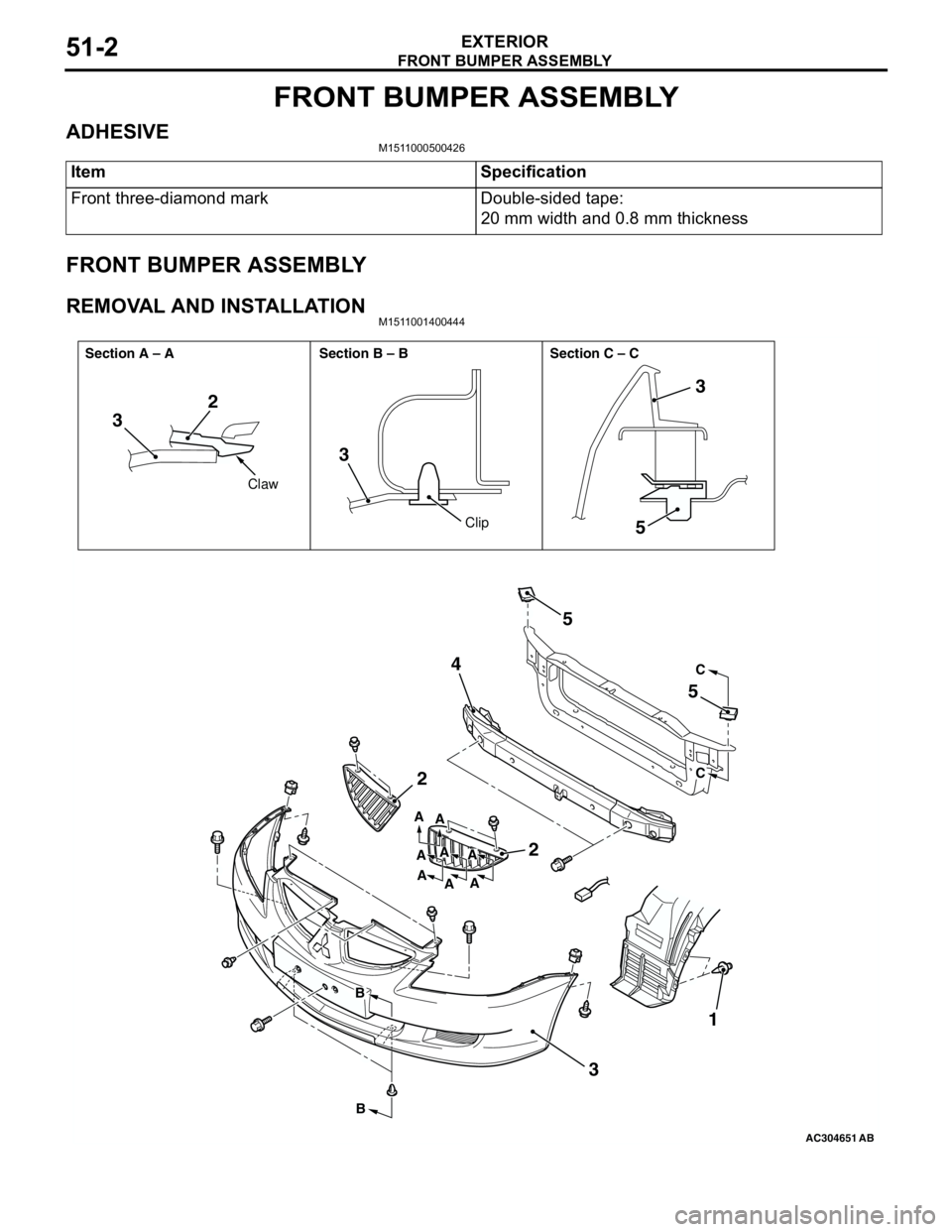
FRONT BUMPER ASSEMBLY
EXTERIOR51-2
FRONT BUMPER ASSEMBLY
ADHESIVEM1511000500426
FRONT BUMPER ASSEMBLY
REMOVAL AND INSTALLATIONM1511001400444
Item Specification
Front three-diamond mark Double-sided tape:
20 mm width and 0.8 mm thickness
AC304651AB
32
3
5
2
2 45
5
31
3
C
C
B
BA
A
A A A
A
AA
Claw
Clip Section A – A Section B – B Section C – C
Page 341 of 788
FRONT BUMPER ASSEMBLY
EXTERIOR51-3
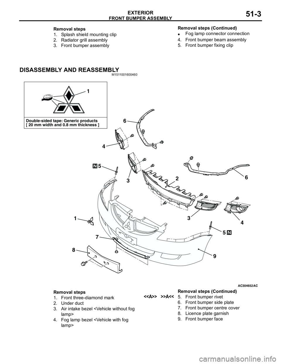
DISASSEMBLY AND REASSEMBLYM1511001600460
Removal steps
1. Splash shield mounting clip
2. Radiator grill assembly
3. Front bumper assembly•Fog lamp connector connection
4. Front bumper beam assembly
5. Front bumper fixing clip Removal steps (Continued)
AC304652AC
Double-sided tape: Generic products
[ 20 mm width and 0.8 mm thickness ]
1
1
8
7
9
6
6
5
5
3
4
34
N
N
2
Removal steps
1. Front three-diamond mark
2. Under duct
3. Air intake bezel
4. Fog lamp bezel
6. Front bumper side plate
7. Front bumper centre cover
8. Licence plate garnish
9. Front bumper face Removal steps (Continued)
Page 342 of 788
Page 347 of 788
MOULDINGS
EXTERIOR51-9
MOULDINGS
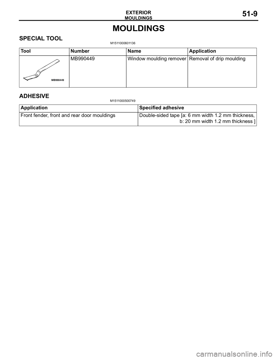
SPECIAL TOOLM1511000601136
ADHESIVEM1511000500749
Tool Number Name Application
MB990449 Window moulding remover Removal of drip moulding
MB990449
Application Specified adhesive
Front fender, front and rear door mouldings Double-sided tape [a: 6 mm width 1.2 mm thickness,
b: 20 mm width 1.2 mm thickness ]
Page 349 of 788
MOULDINGS
EXTERIOR51-11
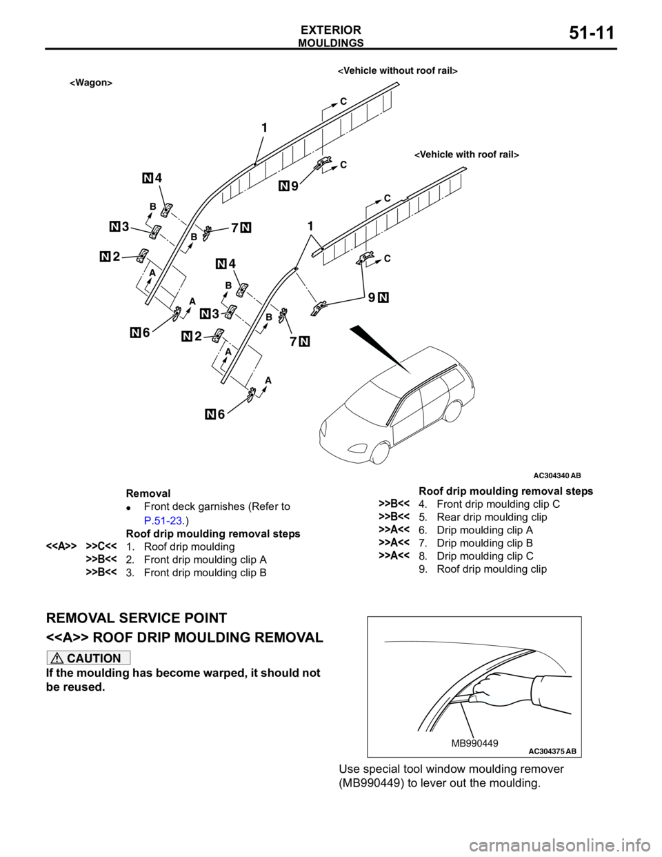
REMOVAL SERVICE POINT
<> ROOF DRIP MOULDING REMOVAL
CAUTION
If the moulding has become warped, it should not
be reused.
Use special tool window moulding remover
(MB990449) to lever out the moulding.
AC304340
1
1
A
A
A
A
AB
B
B
C
C
C
C
B
B
N
N
N
2
N2
4
3
N3
N4
N
6
9
7
N
6N
N
7N
N9
Removal
•Front deck garnishes (Refer to
P.51-23.)
Roof drip moulding removal steps
<> >>C<<1. Roof drip moulding
>>B<<2. Front drip moulding clip A
>>B<<3. Front drip moulding clip B
>>B<<4. Front drip moulding clip C
>>B<<5. Rear drip moulding clip
>>A<<6. Drip moulding clip A
>>A<<7. Drip moulding clip B
>>A<<8. Drip moulding clip C
9. Roof drip moulding clip Roof drip moulding removal steps
AC304375MB990449AB
Page 350 of 788
MOULDINGS
EXTERIOR51-12
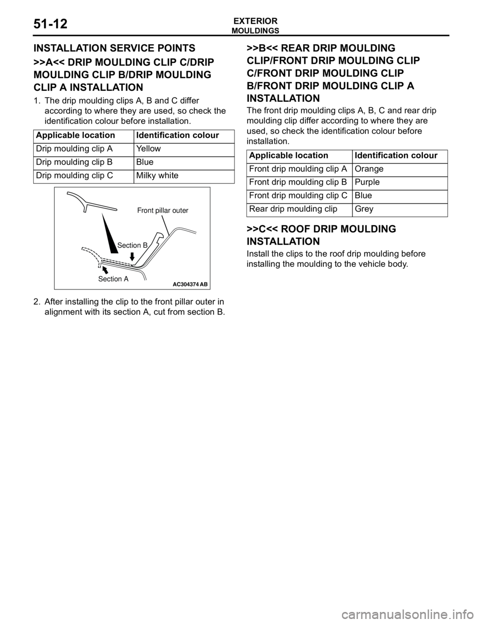
INSTALLATION SERVICE POINTS
>>A<< DRIP MOULDING CLIP C/DRIP
MOULDING CLIP B/DRIP MOULDING
CLIP A INSTALLATION
1. The drip moulding clips A, B and C differ
according to where they are used, so check the
identification colour before installation.
2. After installing the clip to the front pillar outer in
alignment with its section A, cut from section B.
>>B<< REAR DRIP MOULDING
CLIP/FRONT DRIP MOULDING CLIP
C/FRONT DRIP MOULDING CLIP
B/FRONT DRIP MOULDING CLIP A
INSTALLATION
The front drip moulding clips A, B, C and rear drip
moulding clip differ according to where they are
used, so check the identification colour before
installation.
>>C<< ROOF DRIP MOULDING
INSTALLATION
Install the clips to the roof drip moulding before
installing the moulding to the vehicle body. Applicable location Identification colour
Drip moulding clip A Yellow
Drip moulding clip B Blue
Drip moulding clip C Milky white
AC304374
Front pillar outer
Section B
Section A
AB
Applicable location Identification colour
Front drip moulding clip A Orange
Front drip moulding clip B Purple
Front drip moulding clip C Blue
Rear drip moulding clip Grey
Page 351 of 788
MOULDINGS
EXTERIOR51-13
AC401196 AC400117
AC400128
Section A – A Section B – B Section C – C
AB
A
AB
BC
C
2
1
3
ClipClip
AC400840AD
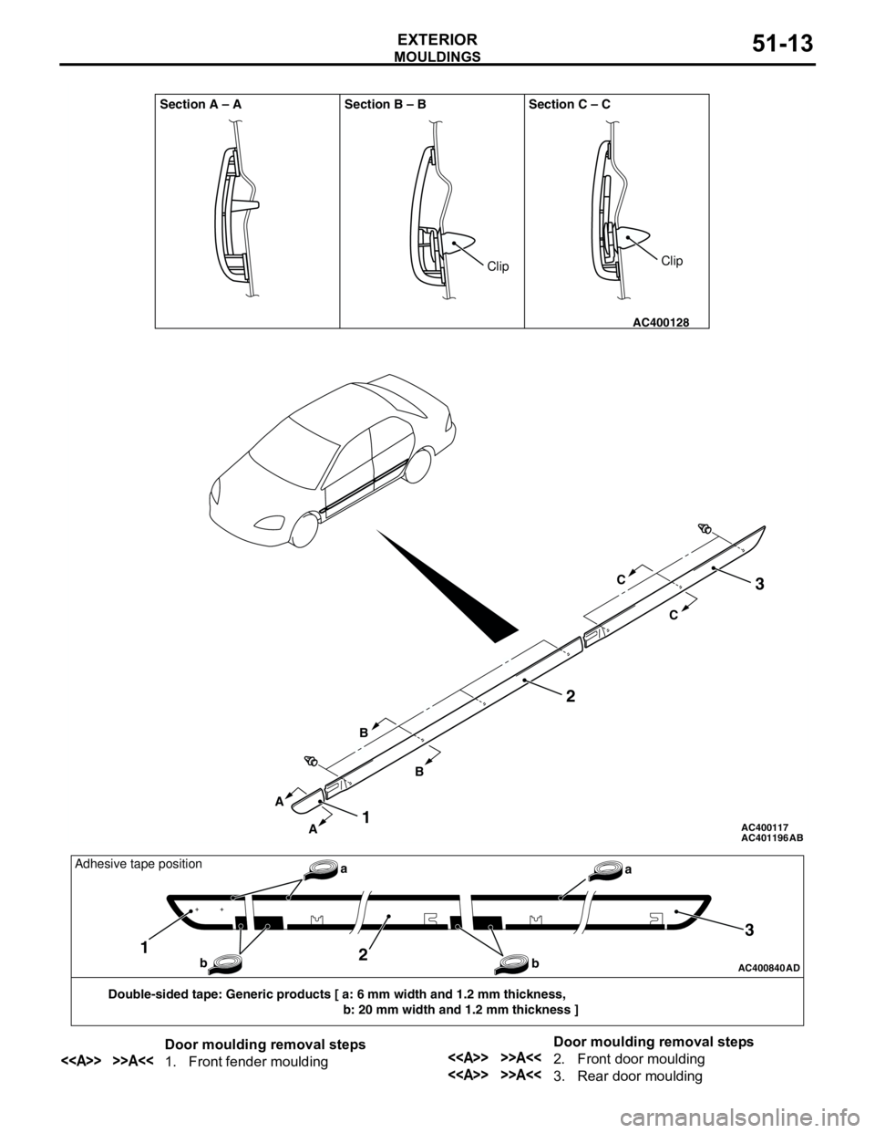
Double-sided tape: Generic products [ a: 6 mm width and 1.2 mm thickness,
b: 20 mm width and 1.2 mm thickness ]
12
3
a
b baAdhesive tape position
Door moulding removal steps
<> >>A<<1. Front fender mouldingDoor moulding removal steps<> >>A<<2. Front door moulding
<> >>A<<3. Rear door moulding
Page 352 of 788
Page 358 of 788
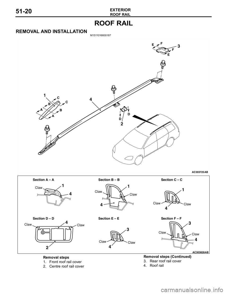
ROOF RAIL
EXTERIOR51-20
ROOF RAIL
REMOVAL AND INSTALLATIONM1511016600187
AC303725
1
4
2
3
AB
A A
A BC
C
B
DDEF EF
AC303828
Section A – A Section B – B Section C – C
Section D – D Section E – E Section F – F
1
4
4
11
4
3
3
4
4
2
4
Claw
Claw
Claw
Claw
Claw
Claw
ClawClaw
Claw
Claw
Claw
AB
Removal steps
1. Front roof rail cover
2. Centre roof rail cover3. Rear roof rail cover
4. Roof rail Removal steps (Continued)
Page 359 of 788

WINDSHIELD WIPER AND WASHER
EXTERIOR51-21
WINDSHIELD WIPER AND WASHER
GENERAL INFORMATIONM1511000100514
WINDSHIELD WIPER AND WASHER
OPERATION
Windshield Low-speed (and High-speed)
Wiper Operation
•If the windshield low-speed wiper switch is turned
to the ON position with the ignition switch at the
"ACC" or "ON" position, the column switch sends
a low-speed wiper ON and high-speed wiper OFF
signals to the front-ECU. This turns the wiper
signal on and the wiper speed control relay off
(low-speed), causing the wipers to operate at
low-speed.
•If the windshield high-speed wiper switch is
turned to the ON position, the column switch
sends a low-speed wiper OFF and high-speed
wiper ON signals to the front-ECU. This turns
both the wiper signal and the wiper speed control
relay on (high-speed), causing the wipers to
operate at high-speed.
NOTE: The windshield wiper speed is switchable
with the built-in wiper speed control relay.
High-speed operations take place when the wiper
speed control relay is set to "ON" and low-speed
operations take place when the wiper speed control
relay is set to "OFF".
Windshield Intermittent Wiper Operation
The ETACS-ECU calculates the wiper operation
interval according to the voltage signal sent from the
column switch. Then the ETACS-ECU sends a signal
to the front-ECU. The front-ECU determines the
wiper operation interval and turns on the wiper relay
signal relay. This causes the wiper auto stop relay to
turn on. Then the wiper auto stop relay will turn off
after the wipers reach the park position. This causes
the wiper signal relay and then the wipers to turn off.
If the wiper signal relay remains off for the wiper
operation interval, the relay turns on again, causing
the wipers to operate in intermittent mode.
Windshield Mist Wiper Operation
•If the windshield mist wiper switch is turned to the
ON position with the ignition switch at the "ACC"
or "ON" position, the mist wiper high-speed
operation signal is sent to the front-ECU. This
signal turns on the wiper speed control relay,
causing the wipers to work at high-speed while
the mist switch is on.
•While the windshield mist wiper switch remains
turned on when the intermittent mode is still
working, the wipers work as the mist wiper.
However, the wipers return to the intermittent
mode again when the switch is changed back to
"INT" position.
•To prevent the windshield mist wiper from
operating when the windshield wiper switch is
turned OFF, the windshield mist wiper does not
work for 0.5 second after the windshield
intermittent wiper switch, the windshield
low-speed wiper switch and the windshield
high-speed wiper switch are turned OFF.
Windshield Washer Operation
•If the windshield washer switch is turned to ON
position with the ignition switch at "ACC" or "ON"
position, the windshield washer ON signal is sent
to the front-ECU. After 0.3 second, the windshield
wiper signal turns on. After the windshield washer
switch signal turns off, the windshield wiper signal
turns off in three seconds.
•If the windshield washer switch is turned on while
the windshield wiper is at intermittent mode,
when the windshield washer switch is turned OFF
within 0.2 second, the wiper works only once to
perform mist operation by the windshield washer
switch. When the ON condition of the windshield
washer switch continues more than 0.2 second,
the wiper performs the same movement as
normal condition from the time when 0.2 second
has elapsed and then returns to the intermittent
motion.