front MITSUBISHI LANCER 2005 Repair Manual
[x] Cancel search | Manufacturer: MITSUBISHI, Model Year: 2005, Model line: LANCER, Model: MITSUBISHI LANCER 2005Pages: 788, PDF Size: 45.98 MB
Page 213 of 788
Page 228 of 788
ON-VEHICLE SERVICE
PARKING BRAKES36-4
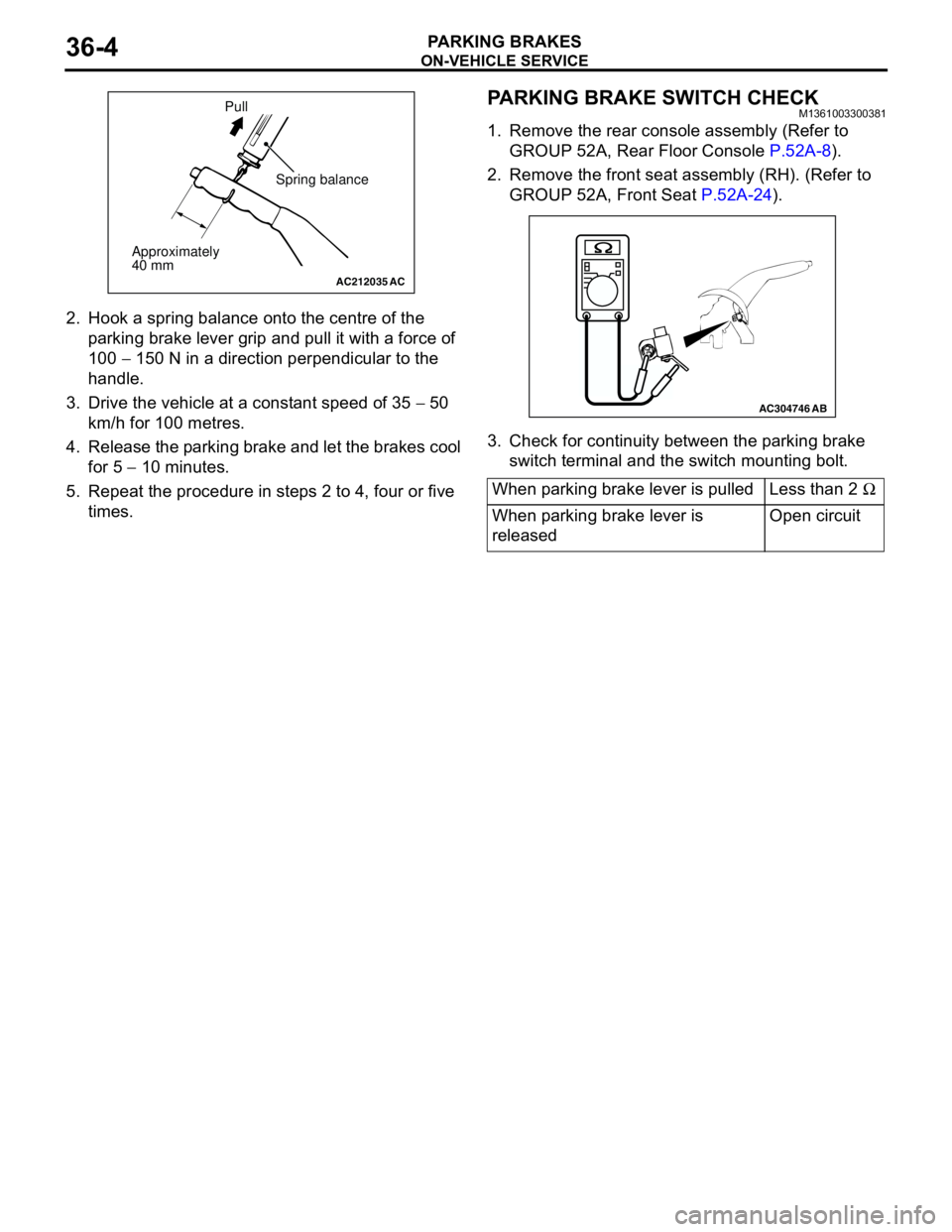
2. Hook a spring balance onto the centre of the
parking brake lever grip and pull it with a force of
100 − 150 N in a direction perpendicular to the
handle.
3. Drive the vehicle at a constant speed of 35 − 50
km/h for 100 metres.
4. Release the parking brake and let the brakes cool
for 5 − 10 minutes.
5. Repeat the procedure in steps 2 to 4, four or five
times.
PARKING BRAKE SWITCH CHECKM1361003300381
1. Remove the rear console assembly (Refer to
GROUP 52A, Rear Floor Console P.52A-8).
2. Remove the front seat assembly (RH). (Refer to
GROUP 52A, Front Seat P.52A-24).
3. Check for continuity between the parking brake
switch terminal and the switch mounting bolt.
AC212035AC
Spring balance
Approximately
40 mmPull
When parking brake lever is pulled Less than 2 Ω
When parking brake lever is
releasedOpen circuit
AC304746AB
Page 232 of 788
Page 233 of 788
PARKING BRAKE LINING AND DRUM
PARKING BRAKES36-9
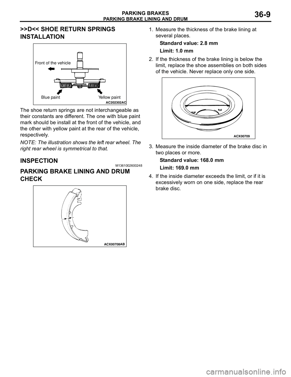
>>D<< SHOE RETURN SPRINGS
INSTALLATION
The shoe return springs are not interchangeable as
their constants are different. The one with blue paint
mark should be install at the front of the vehicle, and
the other with yellow paint at the rear of the vehicle,
respectively.
NOTE: The illustration shows the left rear wheel. The
right rear wheel is symmetrical to that.
INSPECTIONM1361002600248
PARKING BRAKE LINING AND DRUM
CHECK
1. Measure the thickness of the brake lining at
several places.
Standard value: 2.8 mm
Limit: 1.0 mm
2. If the thickness of the brake lining is below the
limit, replace the shoe assemblies on both sides
of the vehicle. Never replace only one side.
3. Measure the inside diameter of the brake disc in
two places or more.
Standard value: 168.0 mm
Limit: 169.0 mm
4. If the inside diameter exceeds the limit, or if it is
excessively worn on one side, replace the rear
brake disc.
AC202302AC
Front of the vehicle
Blue paint Yellow paint
ACX00708AB
ACX00709
Page 235 of 788
37-1
GROUP 37
POWER STEERING
CONTENTS
GENERAL INFORMATION . . . . . . . .37-3
SERVICE SPECIFICATIONS . . . . . . .37-6
LUBRICANTS . . . . . . . . . . . . . . . . . .37-7
SEALANTS . . . . . . . . . . . . . . . . . . . .37-7
SPECIAL TOOLS . . . . . . . . . . . . . . . .37-8
ON-VEHICLE SERVICE . . . . . . . . . . .37-11
STEERING WHEEL FREE PLAY
CHECK . . . . . . . . . . . . . . . . . . . . . . . . . . . . 37-11
STEERING ANGLE CHECK . . . . . . . . . . . . 37-11
TIE ROD END BALL JOINT TURNING
TORQUE CHECK . . . . . . . . . . . . . . . . . . . . 37-12
STATIONARY STEERING EFFORT
CHECK . . . . . . . . . . . . . . . . . . . . . . . . . . . . 37-12
STEERING WHEEL RETURN TO
CENTRE CHECK . . . . . . . . . . . . . . . . . . . . 37-13DRIVE BELT TENSION CHECK . . . . . . . . . 37-13
FLUID LEVEL CHECK . . . . . . . . . . . . . . . . 37-13
FLUID REPLACEMENT . . . . . . . . . . . . . . . 37-13
POWER STEERING SYSTEM AIR
BLEEDING . . . . . . . . . . . . . . . . . . . . . . . . . 37-13
OIL PUMP PRESSURE TEST . . . . . . . . . . 37-14
POWER STEERING PRESSURE
SWITCH CHECK . . . . . . . . . . . . . . . . . . . . . 37-15
TIE ROD END BALL JOINT DUST COVER
CHECK . . . . . . . . . . . . . . . . . . . . . . . . . . . . 37-15
STEERING COLUMN SHAFT
ASSEMBLY SHOCK ABSORBING
MECHANISM CHECK . . . . . . . . . . . . . . . . . 37-15
STEERING WHEEL* . . . . . . . . . . . . . .37-17
REMOVAL AND INSTALLATION
REMOVAL AND INSTALLATION
Continued on next page
WARNINGS REGARDING SERVICING OF SUPPLEMENTAL RESTRAINT SYSTEM (SRS) EQUIPPED VEHICLES
WARNING
•Improper service or maintenance of any component of the SRS, or any SRS-related component, can lead to
personal injury or death to service personnel (from inadvertent firing of the air bag) or to the driver and
paassenger (from rendering the SRS inoperative).
•Service or maintenance of any SRS component or SRS-related component must be performed only at an
authorized MITSUBISHI dealer.
•MITSUBISHI dealer personnel must thoroughly review this manual, and especially its GROUP 52B - Supplemental
Restraint System (SRS) before beginning any service or maintenance of any component of the SRS or any
SRS-related component.
NOTE
The SRS includes the following components: SRS air bag control unit, SRS warning light, front impact sensors, air bag module,
clock spring, and interconnecting wiring. Other SRS-related components (that may have to be removed/installed in connection
with SRS service or maintenance) are indicated in the table of contents by an asterisk (*).
Page 244 of 788
SPECIAL TOOLS
POWER STEERING37-10
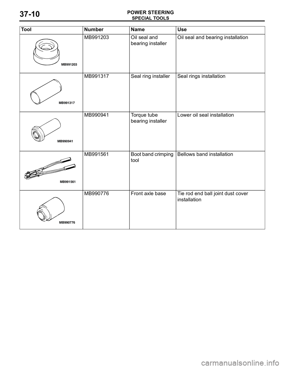
MB991203 Oil seal and
bearing installerOil seal and bearing installation
MB991317 Seal ring installer Seal rings installation
MB990941 Torque tube
bearing installerLower oil seal installation
MB991561 Boot band crimping
toolBellows band installation
MB990776 Front axle base Tie rod end ball joint dust cover
installation Tool Number Name Use
MB991203
MB991317
MB990941
MB991561
MB990776
Page 245 of 788
ON-VEHICLE SERVICE
POWER STEERING37-11
ON-VEHICLE SERVICE
STEERING WHEEL FREE PLAY CHECKM1372001000311
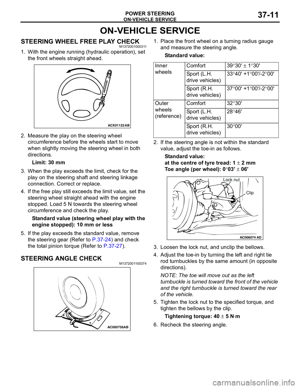
1. With the engine running (hydraulic operation), set
the front wheels straight ahead.
2. Measure the play on the steering wheel
circumference before the wheels start to move
when slightly moving the steering wheel in both
directions.
Limit: 30 mm
3. When the play exceeds the limit, check for the
play on the steering shaft and steering linkage
connection. Correct or replace.
4. If the free play still exceeds the limit value, set the
steering wheel straight ahead with the engine
stopped. Load 5 N towards the steering wheel
circumference and check the play.
Standard value (steering wheel play with the
engine stopped): 10 mm or less
5. If the play exceeds the standard value, remove
the steering gear (Refer to P.37-24) and check
the total pinion torque (Refer to P.37-27).
STEERING ANGLE CHECKM1372001100374
1. Place the front wheel on a turning radius gauge
and measure the steering angle.
Standard value:
2. If the steering angle is not within the standard
value, adjust the toe-in as follows.
Standard value:
at the centre of tyre tread: 1 ± 2 mm
Toe angle (per wheel): 0°03' ± 06'
3. Loosen the lock nut, and unclip the bellows.
4. Adjust the toe-in by turning the left and right tie
rod turnbuckles by the same amount (in opposite
directions).
NOTE: The toe will move out as the left
turnbuckle is turned toward the front of the vehicle
and the right turnbuckle is turned toward the rear
of the vehicle.
5. Tighten the lock nut to the specified torque, and
tighten the bellows by the clip.
Tightening torque: 40 ± 5 N⋅m
6. Recheck the steering angle.
ACX01122
AB
AC000756AB
Inner
wheelsComfort 39°30' ± 1°30'
Sport (L.H.
drive vehicles)33°40' +1°00'/-2°00'
Sport (R.H.
drive vehicles)37°00' +1°00'/-2°00'
Outer
wheels
(reference)Comfort 32°30'
Sport (L.H.
drive vehicles)28°46'
Sport (R.H.
drive vehicles)30°00'
AC006074AD
Lock nut
Clip
Page 247 of 788
ON-VEHICLE SERVICE
POWER STEERING37-13
STEERING WHEEL RETURN TO CENTRE
CHECK
M1372001800317
Conduct a road test:
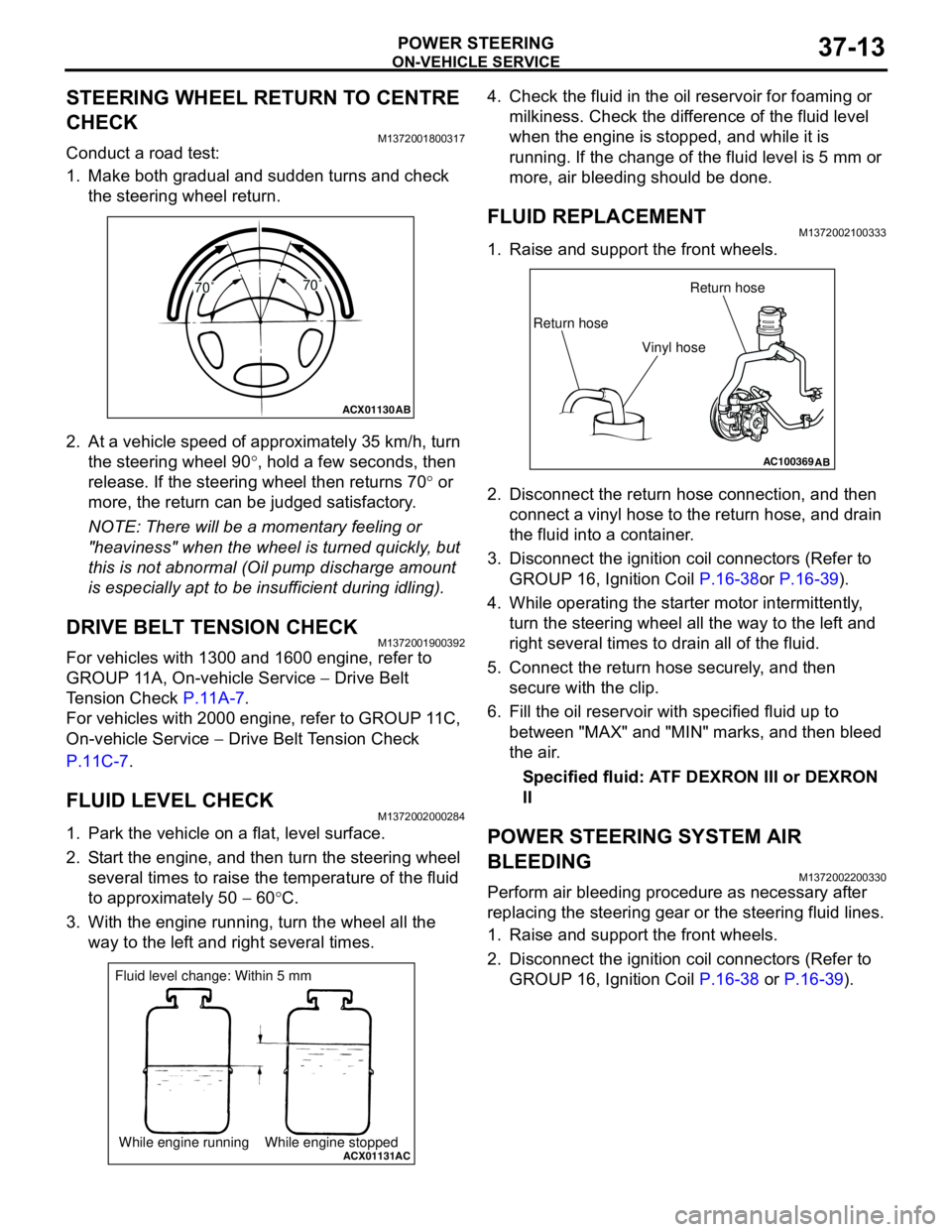
1. Make both gradual and sudden turns and check
the steering wheel return.
2. At a vehicle speed of approximately 35 km/h, turn
the steering wheel 90°, hold a few seconds, then
release. If the steering wheel then returns 70° or
more, the return can be judged satisfactory.
NOTE: There will be a momentary feeling or
"heaviness" when the wheel is turned quickly, but
this is not abnormal (Oil pump discharge amount
is especially apt to be insufficient during idling).
DRIVE BELT TENSION CHECKM1372001900392
For vehicles with 1300 and 1600 engine, refer to
GROUP 11A, On-vehicle Service − Drive Belt
Tension Check P.11A-7.
For vehicles with 2000 engine, refer to GROUP 11C,
On-vehicle Service − Drive Belt Tension Check
P.11C-7.
FLUID LEVEL CHECKM1372002000284
1. Park the vehicle on a flat, level surface.
2. Start the engine, and then turn the steering wheel
several times to raise the temperature of the fluid
to approximately 50 − 60°C.
3. With the engine running, turn the wheel all the
way to the left and right several times.4. Check the fluid in the oil reservoir for foaming or
milkiness. Check the difference of the fluid level
when the engine is stopped, and while it is
running. If the change of the fluid level is 5 mm or
more, air bleeding should be done.
FLUID REPLACEMENTM1372002100333
1. Raise and support the front wheels.
2. Disconnect the return hose connection, and then
connect a vinyl hose to the return hose, and drain
the fluid into a container.
3. Disconnect the ignition coil connectors (Refer to
GROUP 16, Ignition Coil P.16-38or P.16-39).
4. While operating the starter motor intermittently,
turn the steering wheel all the way to the left and
right several times to drain all of the fluid.
5. Connect the return hose securely, and then
secure with the clip.
6. Fill the oil reservoir with specified fluid up to
between "MAX" and "MIN" marks, and then bleed
the air.
Specified fluid: ATF DEXRON III or DEXRON
II
POWER STEERING SYSTEM AIR
BLEEDING
M1372002200330
Perform air bleeding procedure as necessary after
replacing the steering gear or the steering fluid lines.
1. Raise and support the front wheels.
2. Disconnect the ignition coil connectors (Refer to
GROUP 16, Ignition Coil P.16-38 or P.16-39).
ACX01130
AB
70˚70˚
ACX01131While engine running While engine stoppedAC
Fluid level change: Within 5 mm
AC100369AB
Return hoseReturn hose
Vinyl hose
Page 258 of 788
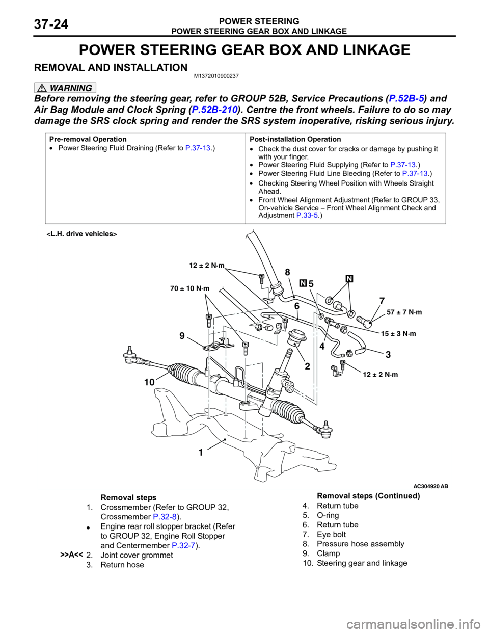
POWER STEERING GEAR BOX AND LINKAGE
POWER STEERING37-24
POWER STEERING GEAR BOX AND LINKAGE
REMOVAL AND INSTALLATIONM1372010900237
WARNING
Before removing the steering gear, refer to GROUP 52B, Service Precautions (P.52B-5) and
Air Bag Module and Clock Spring (P.52B-210). Centre the front wheels. Failure to do so may
damage the SRS clock spring and render the SRS system inoperative, risking serious injury.
Pre-removal Operation
•Power Steering Fluid Draining (Refer to P.37-13.)Post-installation Operation
•Check the dust cover for cracks or damage by pushing it
with your finger.
•Power Steering Fluid Supplying (Refer to P.37-13.)
•Power Steering Fluid Line Bleeding (Refer to P.37-13.)
•Checking Steering Wheel Position with Wheels Straight
Ahead.
•Front Wheel Alignment Adjustment (Refer to GROUP 33,
On-vehicle Service − Front Wheel Alignment Check and
Adjustment P.33-5.)
AC304920
AB
57 ± 7 N·m
15 ± 3 N·m 70 ± 10 N·m
7
3 8
5
6
9
1024
1
12 ± 2 N·m
12 ± 2 N·m
Removal steps
1. Crossmember (Refer to GROUP 32,
Crossmember P.32-8).
•Engine rear roll stopper bracket (Refer
to GROUP 32, Engine Roll Stopper
and Centermember P.32-7).
>>A<<2. Joint cover grommet
3. Return hose4. Return tube
5. O-ring
6. Return tube
7. Eye bolt
8. Pressure hose assembly
9. Clamp
10. Steering gear and linkageRemoval steps (Continued)
Page 270 of 788
POWER STEERING GEAR BOX AND LINKAGE
POWER STEERING37-36
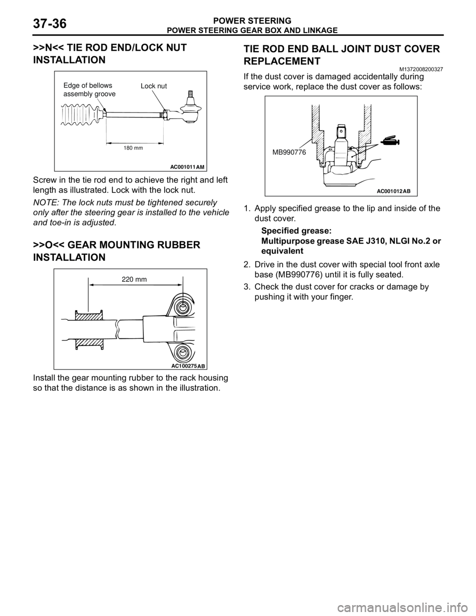
>>N<< TIE ROD END/LOCK NUT
INSTALLATION
Screw in the tie rod end to achieve the right and left
length as illustrated. Lock with the lock nut.
NOTE: The lock nuts must be tightened securely
only after the steering gear is installed to the vehicle
and toe-in is adjusted.
>>O<< GEAR MOUNTING RUBBER
INSTALLATION
Install the gear mounting rubber to the rack housing
so that the distance is as shown in the illustration.
TIE ROD END BALL JOINT DUST COVER
REPLACEMENT
M1372008200327
If the dust cover is damaged accidentally during
service work, replace the dust cover as follows:
1. Apply specified grease to the lip and inside of the
dust cover.
Specified grease:
Multipurpose grease SAE J310, NLGI No.2 or
equivalent
2. Drive in the dust cover with special tool front axle
base (MB990776) until it is fully seated.
3. Check the dust cover for cracks or damage by
pushing it with your finger.
AC001011
AM
Lock nut Edge of bellows
assembly groove
180 mm
AC100275
AB
220 mm
AC001012
AB
MB990776