Body MITSUBISHI LANCER 2005 Workshop Manual
[x] Cancel search | Manufacturer: MITSUBISHI, Model Year: 2005, Model line: LANCER, Model: MITSUBISHI LANCER 2005Pages: 788, PDF Size: 45.98 MB
Page 473 of 788
HAZARD WARNING LAMP SWITCH
CHASSIS ELECTRICAL54A-85
HAZARD WARNING LAMP SWITCH
TROUBLESHOOTING
M1542000701333
FLASHER TIMER FUNCTION
The hazard warning lamps (flasher timer function)
are controlled by the Smart Wiring System (SWS).
For troubleshooting, refer to respective Groups
below.•Not using SWS monitor: GROUP 54B, SWS
Troubleshooting P.54B-38.
•Using SWS monitor: GROUP 54C, SWS
Troubleshooting P.54C-22.
SPECIAL TOOL
M1542000600935
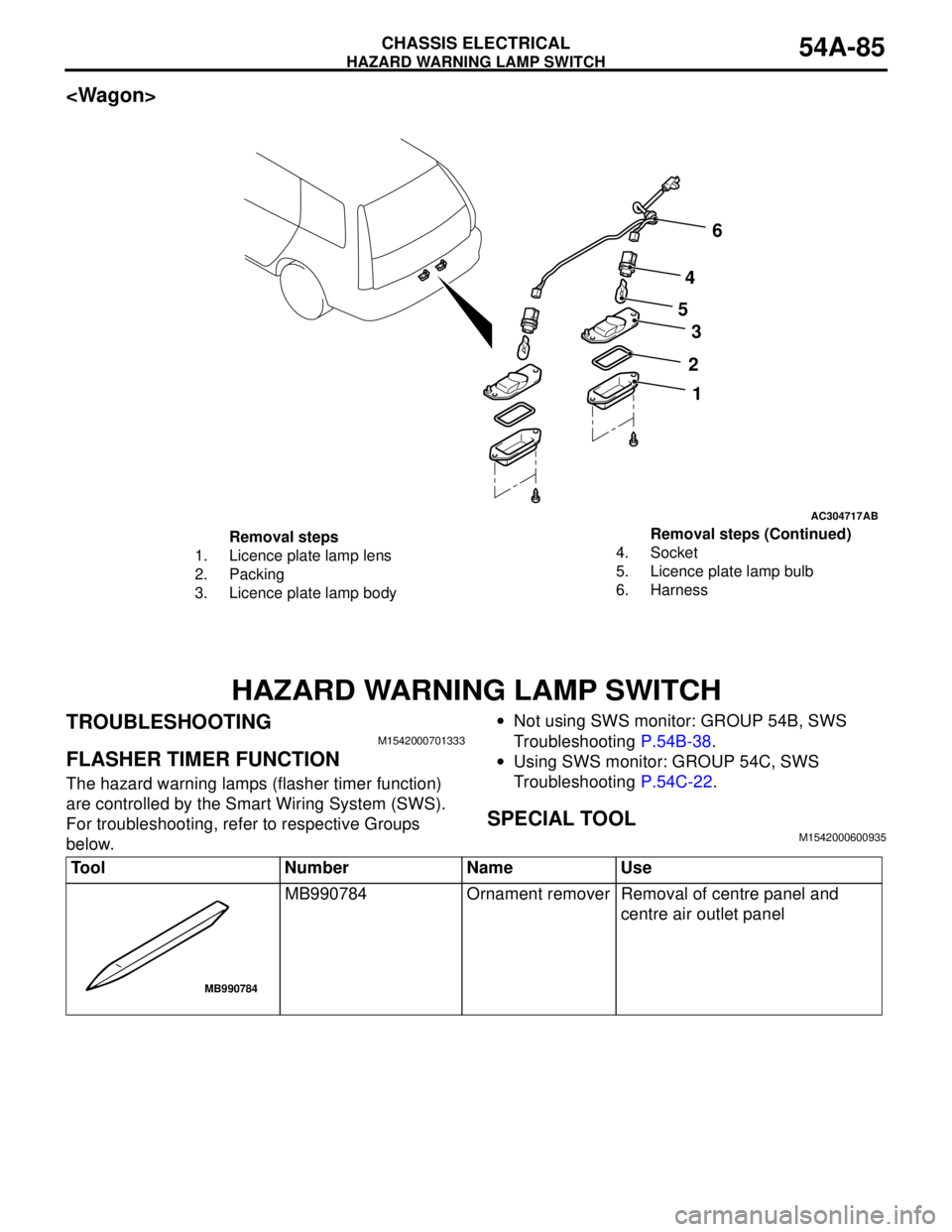
AC304717AB
2
1 3 4
56
Removal steps
1. Licence plate lamp lens
2. Packing
3. Licence plate lamp body4. Socket
5. Licence plate lamp bulb
6. HarnessRemoval steps (Continued)
Tool Number Name Use
MB990784 Ornament remover Removal of centre panel and
centre air outlet panel
MB990784
Page 491 of 788
TROUBLESHOOTING
HEATER, AIR CONDITIONER AND VENTILATION55-7
DIAGNOSIS
STEP 1. Check the defogger and A/C operations.
Q: Do the defogger and A/C work normally?
YES :
Go to Step 2.
NO
"Malfunction of the A/C-ECU power supply
system
NO
"Malfunction of the A/C-ECU power supply
system
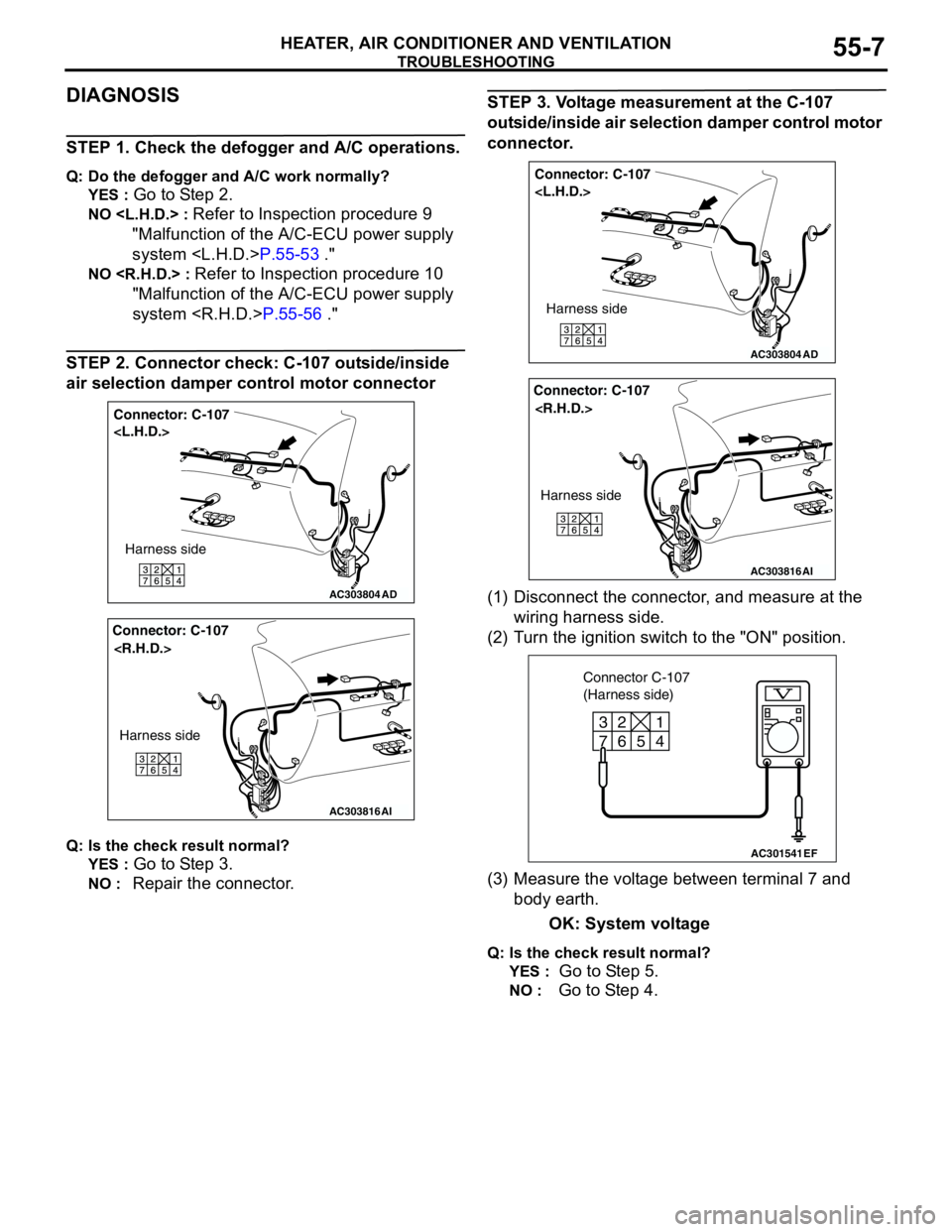
STEP 2. Connector check: C-107 outside/inside
air selection damper control motor connector
Q: Is the check result normal?
YES :
Go to Step 3.
NO : Repair the connector.
STEP 3. Voltage measurement at the C-107
outside/inside air selection damper control motor
connector.
(1) Disconnect the connector, and measure at the
wiring harness side.
(2) Turn the ignition switch to the "ON" position.
(3) Measure the voltage between terminal 7 and
body earth.
OK: System voltage
Q: Is the check result normal?
YES :
Go to Step 5.
NO : Go to Step 4.
AC303804
Connector: C-107
AD
Harness side
AC303816
Connector: C-107
AI
Harness side
AC303804
Connector: C-107
AD
Harness side
AC303816
Connector: C-107
AI
Harness side
AC301541
6 2
7
3
5
4
1
EF
Connector C-107
(Harness side)
Page 497 of 788
TROUBLESHOOTING
HEATER, AIR CONDITIONER AND VENTILATION55-13
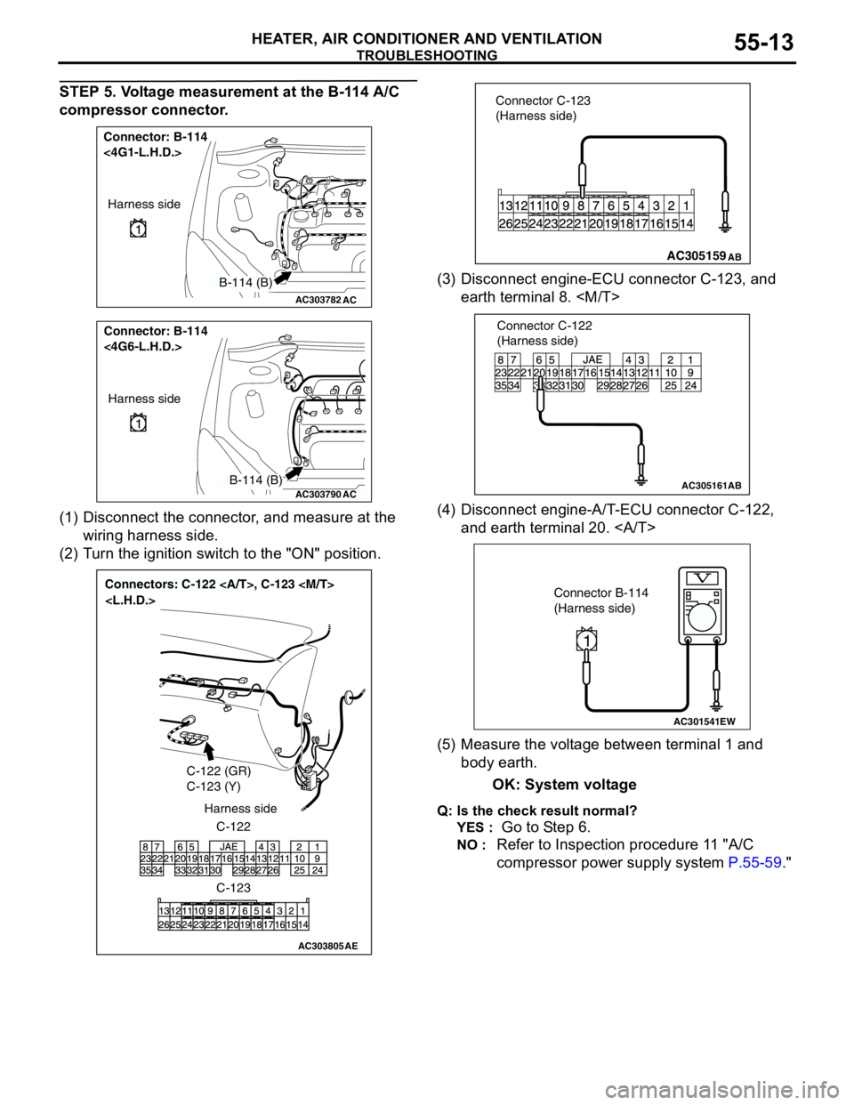
STEP 5. Voltage measurement at the B-114 A/C
compressor connector.
(1) Disconnect the connector, and measure at the
wiring harness side.
(2) Turn the ignition switch to the "ON" position.(3) Disconnect engine-ECU connector C-123, and
earth terminal 8.
(4) Disconnect engine-A/T-ECU connector C-122,
and earth terminal 20.
(5) Measure the voltage between terminal 1 and
body earth.
OK: System voltage
Q: Is the check result normal?
YES :
Go to Step 6.
NO : Refer to Inspection procedure 11 "A/C
compressor power supply system P.55-59."
AC303782
Connector: B-114
<4G1-L.H.D.>
AC
Harness side
B-114 (B)
AC303790
Connector: B-114
<4G6-L.H.D.>
AC
Harness side
B-114 (B)
AC303805
Connectors: C-122 , C-123
C-122 (GR)
C-123 (Y)
C-122 Harness side
C-123
AE
AC305159 Connector C-123
(Harness side)AB
AC305161
Connector C-122
(Harness side)
AB
AC301541EW
Connector B-114
(Harness side)
1
Page 498 of 788
TROUBLESHOOTING
HEATER, AIR CONDITIONER AND VENTILATION55-14
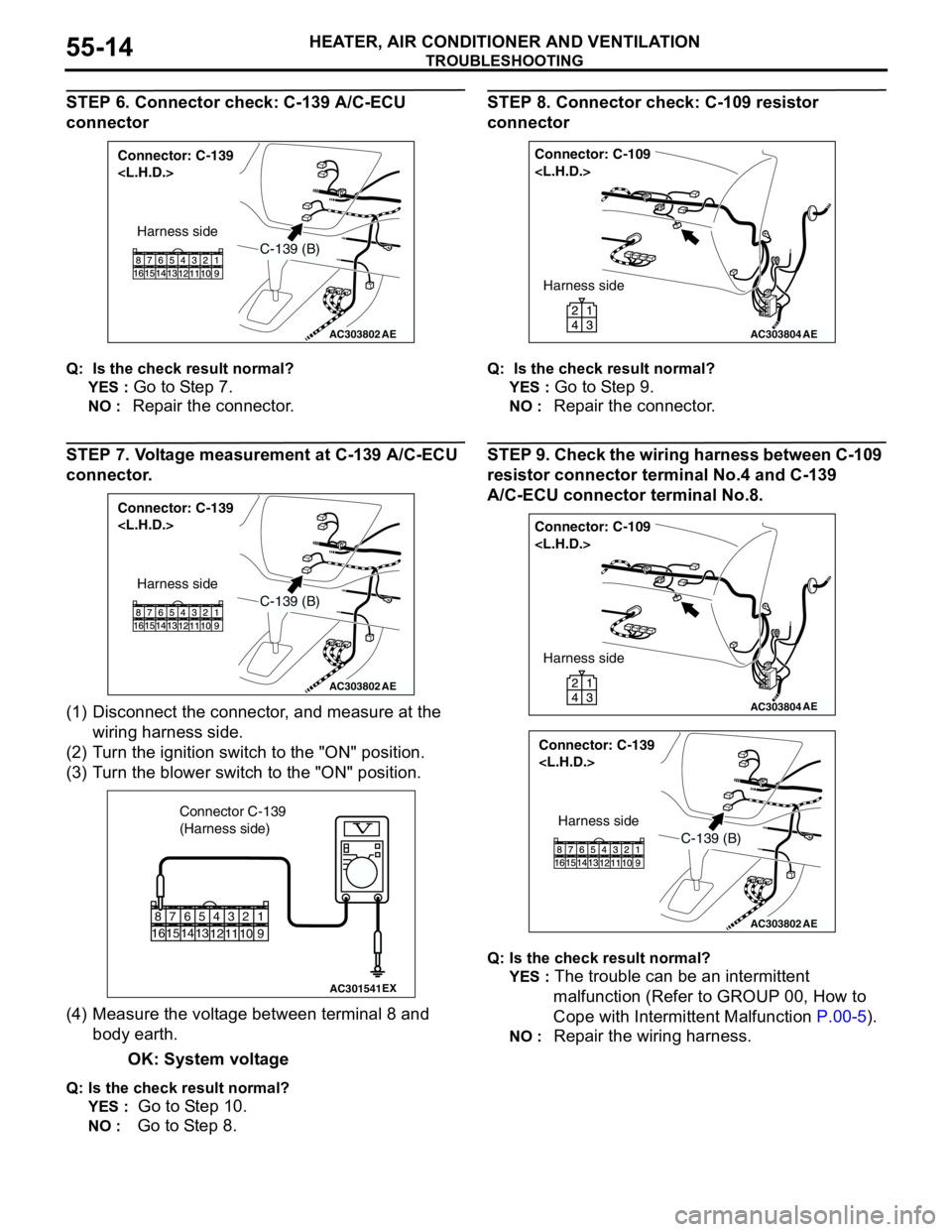
STEP 6. Connector check: C-139 A/C-ECU
connector
Q: Is the check result normal?
YES :
Go to Step 7.
NO : Repair the connector.
STEP 7. Voltage measurement at C-139 A/C-ECU
connector.
(1) Disconnect the connector, and measure at the
wiring harness side.
(2) Turn the ignition switch to the "ON" position.
(3) Turn the blower switch to the "ON" position.
(4) Measure the voltage between terminal 8 and
body earth.
OK: System voltage
Q: Is the check result normal?
YES :
Go to Step 10.
NO : Go to Step 8.
STEP 8. Connector check: C-109 resistor
connector
Q: Is the check result normal?
YES :
Go to Step 9.
NO : Repair the connector.
STEP 9. Check the wiring harness between C-109
resistor connector terminal No.4 and C-139
A/C-ECU connector terminal No.8.
Q: Is the check result normal?
YES :
The trouble can be an intermittent
malfunction (Refer to GROUP 00, How to
Cope with Intermittent Malfunction P.00-5).
NO : Repair the wiring harness.
AC303802
Connector: C-139
AE
C-139 (B)
Harness side
AC303802
Connector: C-139
AE
C-139 (B)
Harness side
AC301541EX
Connector C-139
(Harness side)
9
1
1574
12
1110
23
13
5
14616
8
AC303804
Connector: C-109
AE
Harness side
AC303804
Connector: C-109
AE
Harness side
AC303802
Connector: C-139
AE
C-139 (B)
Harness side
Page 506 of 788
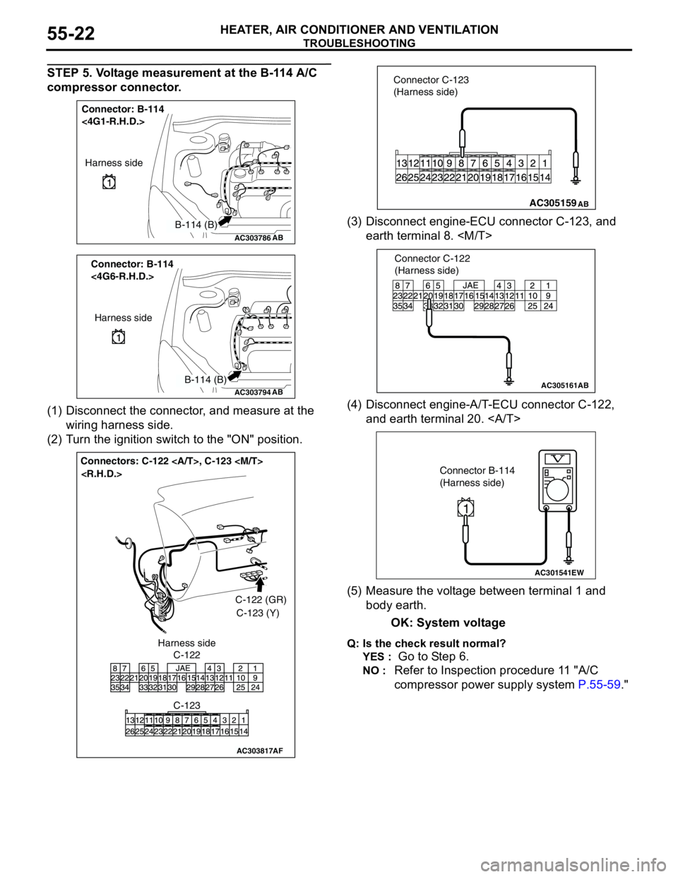
TROUBLESHOOTING
HEATER, AIR CONDITIONER AND VENTILATION55-22
STEP 5. Voltage measurement at the B-114 A/C
compressor connector.
(1) Disconnect the connector, and measure at the
wiring harness side.
(2) Turn the ignition switch to the "ON" position.(3) Disconnect engine-ECU connector C-123, and
earth terminal 8.
(4) Disconnect engine-A/T-ECU connector C-122,
and earth terminal 20.
(5) Measure the voltage between terminal 1 and
body earth.
OK: System voltage
Q: Is the check result normal?
YES :
Go to Step 6.
NO : Refer to Inspection procedure 11 "A/C
compressor power supply system P.55-59."
AC303786
Connector: B-114
<4G1-R.H.D.>
AB
Harness side
B-114 (B)
AC303794
Connector: B-114
<4G6-R.H.D.>
AB
Harness side
B-114 (B)
AC303817
Connectors: C-122 , C-123
AF
C-122C-122 (GR)
C-123 (Y)
C-123 Harness side
AC305159 Connector C-123
(Harness side)AB
AC305161
Connector C-122
(Harness side)
AB
AC301541EW
Connector B-114
(Harness side)
1
Page 507 of 788

TROUBLESHOOTING
HEATER, AIR CONDITIONER AND VENTILATION55-23
STEP 6. Connector check: C-139 A/C-ECU
connector
Q: Is the check result normal?
YES :
Go to Step 7.
NO : Repair the connector.
STEP 7. Voltage measurement at C-139 A/C-ECU
connector.
(1) Disconnect the connector, and measure at the
wiring harness side.
(2) Turn the ignition switch to the "ON" position.
(3) Turn the blower switch to the "ON" position.
(4) Measure the voltage between terminal 8 and
body earth.
OK: System voltage
Q: Is the check result normal?
YES :
Go to Step 10.
NO : Go to Step 8.
STEP 8. Connector check: C-109 resistor
connector
Q: Is the check result normal?
YES :
Go to Step 9.
NO : Repair the connector.
STEP 9. Check the wiring harness between C-109
resistor connector terminal No.4 and C-139
A/C-ECU connector terminal No.8.
Q: Is the check result normal?
YES :
The trouble can be an intermittent
malfunction (Refer to GROUP 00, How to
Cope with Intermittent Malfunction P.00-5).
NO : Repair the wiring harness.
AC303818
Connector: C-139
AJ
Harness side
C-139 (B)
11 12657 8 9 103 421
AC303818
Connector: C-139
AJ
Harness side
C-139 (B)
11 12657 8 9 103 421
AC301541EY
Connector C-139
(Harness side)
11 12
65
7 8 9 10
3 421
AC303816
Connector: C-109
AJ
Harness side
AC303816
Connector: C-109
AJ
Harness side
AC303818
Connector: C-139
AJ
Harness side
C-139 (B)
11 12657 8 9 103 421
Page 514 of 788
TROUBLESHOOTING
HEATER, AIR CONDITIONER AND VENTILATION55-30
COMMENTS ON TROUBLE SYMPTOM
If the blower fan and motor does not turn when the
blower switch is operated, the blower switch may be
defective.
TROUBLESHOOTING HINTS
•Malfunction of the blower relay
•Malfunction of the blower switch
•Damaged the wiring harness or connectors
•Malfunction of the blower motor
DIAGNOSIS
STEP 1. Check that the blower motor operates
when the blower switch is moved to the "4 (HI) "
position.
(1) Turn the ignition switch to the "ON" position.
(2) Turn the blower switch to the "4 (HI) " position.
Q: Does the blower motor operate when the blower
switch is moved to the "4 (HI) " position?
YES :
Refer to Inspection procedure 6 "Blower air
amount cannot be changed P.55-39."
NO : Go to Step 2.
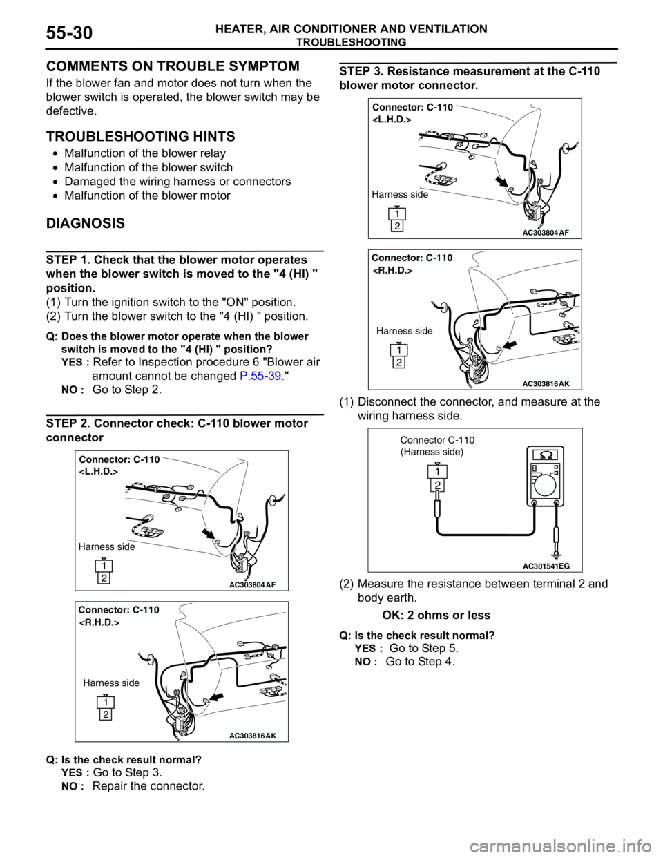
STEP 2. Connector check: C-110 blower motor
connector
Q: Is the check result normal?
YES :
Go to Step 3.
NO : Repair the connector.
STEP 3. Resistance measurement at the C-110
blower motor connector.
(1) Disconnect the connector, and measure at the
wiring harness side.
(2) Measure the resistance between terminal 2 and
body earth.
OK: 2 ohms or less
Q: Is the check result normal?
YES :
Go to Step 5.
NO : Go to Step 4.
AC303804
Connector: C-110
AF
Harness side
AC303816
Connector: C-110
AK
Harness side
AC303804
Connector: C-110
AF
Harness side
AC303816
Connector: C-110
AK
Harness side
AC301541EG
Connector C-110
(Harness side)
2
1
Page 515 of 788
TROUBLESHOOTING
HEATER, AIR CONDITIONER AND VENTILATION55-31
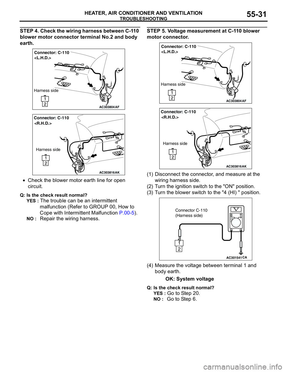
STEP 4. Check the wiring harness between C-110
blower motor connector terminal No.2 and body
earth.
•Check the blower motor earth line for open
circuit.
Q: Is the check result normal?
YES :
The trouble can be an intermittent
malfunction (Refer to GROUP 00, How to
Cope with Intermittent Malfunction P.00-5).
NO : Repair the wiring harness.
STEP 5. Voltage measurement at C-110 blower
motor connector.
(1) Disconnect the connector, and measure at the
wiring harness side.
(2) Turn the ignition switch to the "ON" position.
(3) Turn the blower switch to the "4 (HI) " position.
(4) Measure the voltage between terminal 1 and
body earth.
OK: System voltage
Q: Is the check result normal?
YES :
Go to Step 20.
NO : Go to Step 6.
AC303804
Connector: C-110
AF
Harness side
AC303816
Connector: C-110
AK
Harness side
AC303804
Connector: C-110
AF
Harness side
AC303816
Connector: C-110
AK
Harness side
AC301541CA
Connector C-110
(Harness side)
2
1
Page 517 of 788
TROUBLESHOOTING
HEATER, AIR CONDITIONER AND VENTILATION55-33
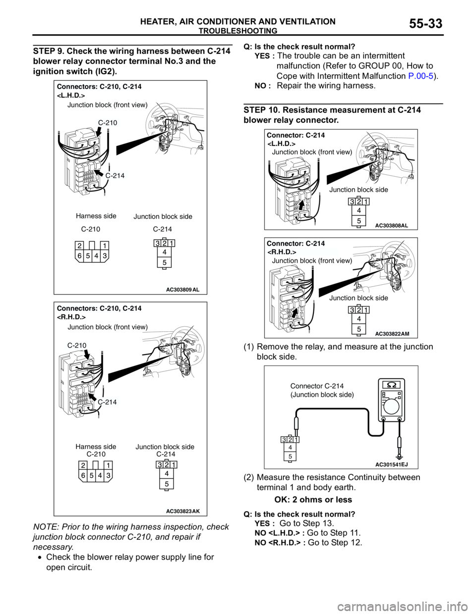
STEP 9. Check the wiring harness between C-214
blower relay connector terminal No.3 and the
ignition switch (IG2).
NOTE: Prior to the wiring harness inspection, check
junction block connector C-210, and repair if
necessary.
•Check the blower relay power supply line for
open circuit.Q: Is the check result normal?
YES :
The trouble can be an intermittent
malfunction (Refer to GROUP 00, How to
Cope with Intermittent Malfunction P.00-5).
NO : Repair the wiring harness.
STEP 10. Resistance measurement at C-214
blower relay connector.
(1) Remove the relay, and measure at the junction
block side.
(2) Measure the resistance Continuity between
terminal 1 and body earth.
OK: 2 ohms or less
Q: Is the check result normal?
YES :
Go to Step 13.
NO
NO
AC303809
Connectors: C-210, C-214
AL
C-214
C-210
Junction block (front view)
C-210 Harness side
Junction block side
C-214
AC303823
Junction block side Junction block (front view)
Connectors: C-210, C-214
C-210C-214 Harness side
C-214
C-210
AK
AC303808
Junction block side Junction block (front view)
Connector: C-214
AL
AC303822
Junction block side Junction block (front view)
Connector: C-214
AM
AC301541EJ
Connector C-214
(Junction block side)
3
4
5
12
Page 519 of 788
TROUBLESHOOTING
HEATER, AIR CONDITIONER AND VENTILATION55-35
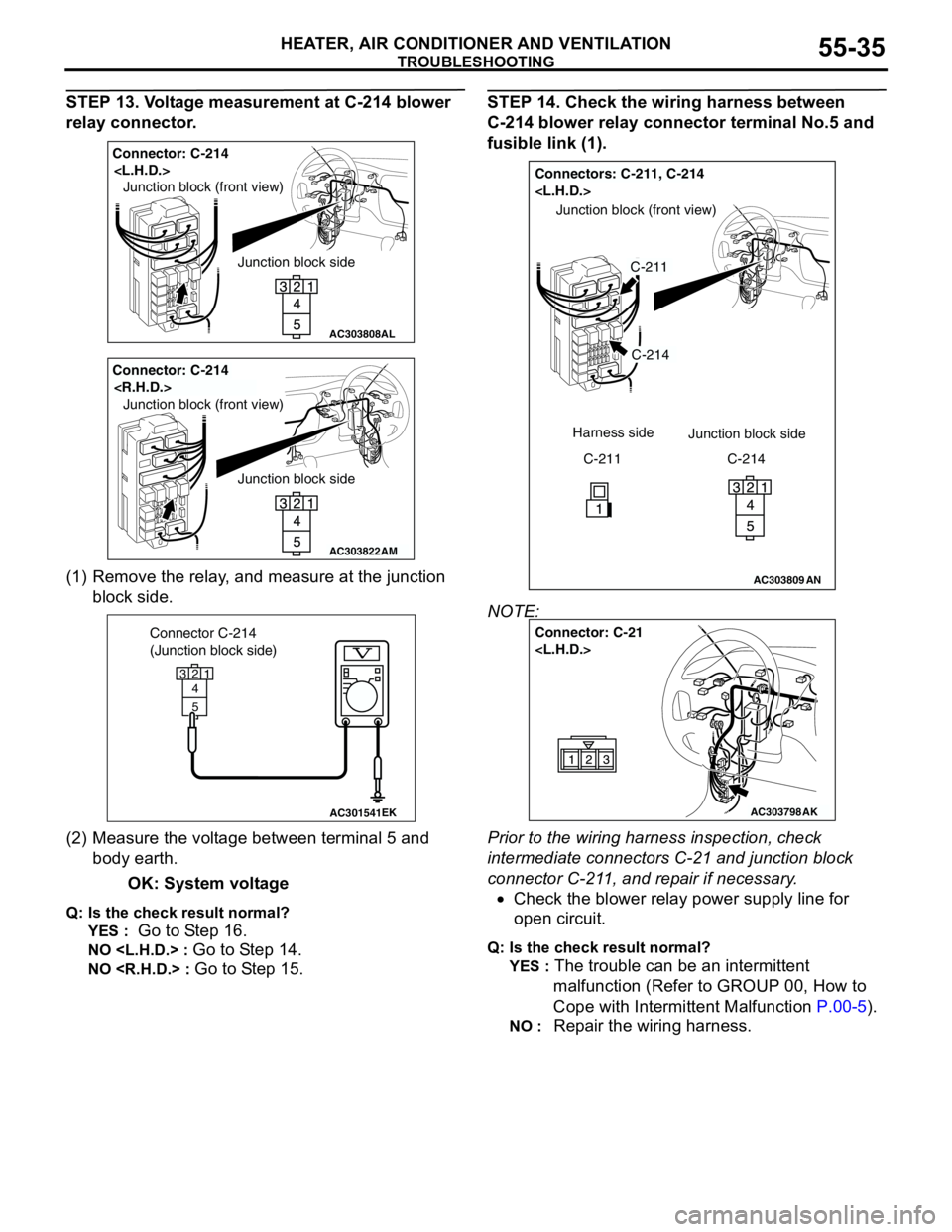
STEP 13. Voltage measurement at C-214 blower
relay connector.
(1) Remove the relay, and measure at the junction
block side.
(2) Measure the voltage between terminal 5 and
body earth.
OK: System voltage
Q: Is the check result normal?
YES :
Go to Step 16.
NO
NO
STEP 14. Check the wiring harness between
C-214 blower relay connector terminal No.5 and
fusible link (1).
NOTE:
Prior to the wiring harness inspection, check
intermediate connectors C-21 and junction block
connector C-211, and repair if necessary.
•Check the blower relay power supply line for
open circuit.
Q: Is the check result normal?
YES :
The trouble can be an intermittent
malfunction (Refer to GROUP 00, How to
Cope with Intermittent Malfunction P.00-5).
NO : Repair the wiring harness.
AC303808
Junction block side Junction block (front view)
Connector: C-214
AL
AC303822
Junction block side Junction block (front view)
Connector: C-214
AM
AC301541EK
Connector C-214
(Junction block side)
3
4
5
12
AC303809
Connectors: C-211, C-214
AN
C-214
C-211
Junction block (front view)
C-211 Harness side
Junction block side
C-214
AC303798
Connector: C-21
AK