Body MITSUBISHI LANCER 2005 Workshop Manual
[x] Cancel search | Manufacturer: MITSUBISHI, Model Year: 2005, Model line: LANCER, Model: MITSUBISHI LANCER 2005Pages: 788, PDF Size: 45.98 MB
Page 528 of 788
TROUBLESHOOTING
HEATER, AIR CONDITIONER AND VENTILATION55-44
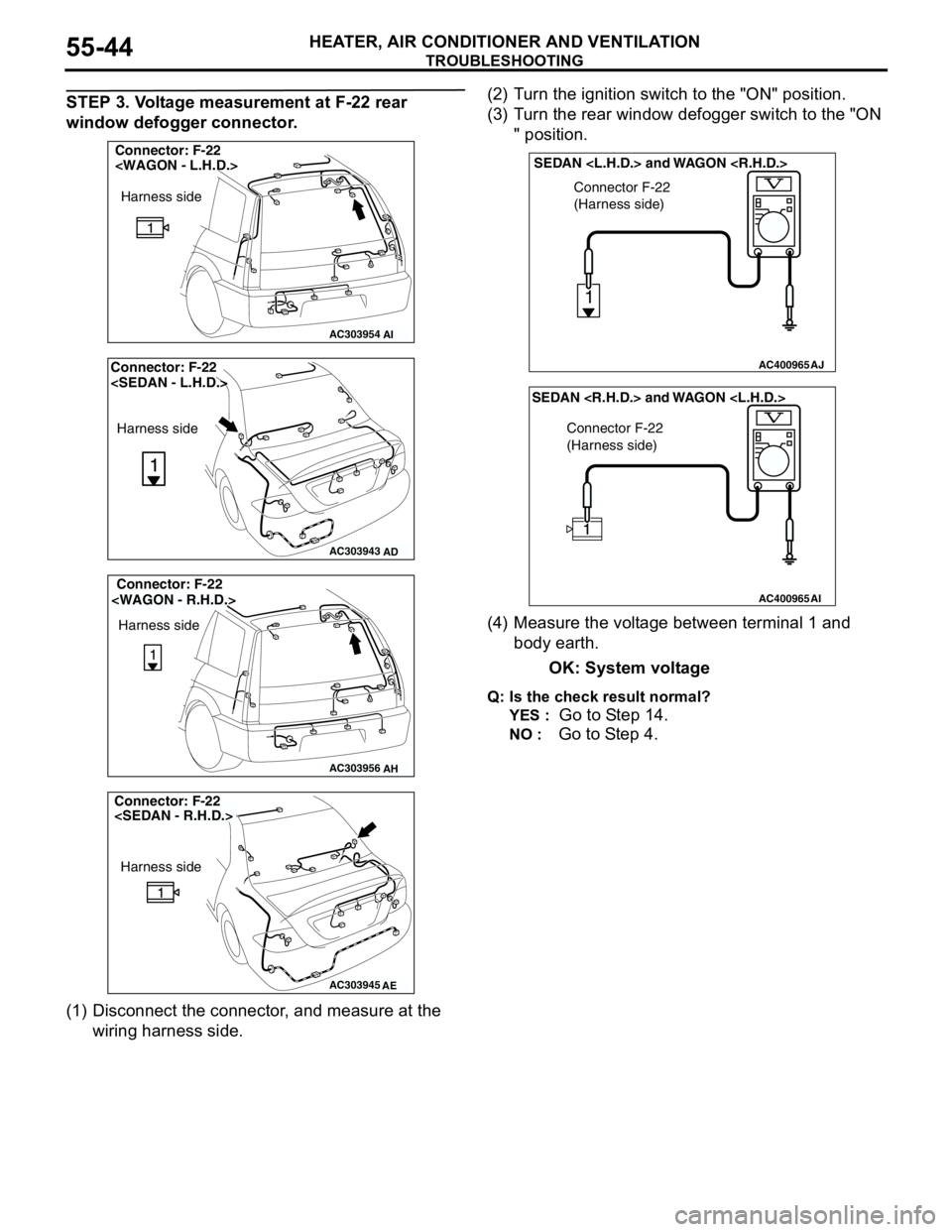
STEP 3. Voltage measurement at F-22 rear
window defogger connector.
(1) Disconnect the connector, and measure at the
wiring harness side.(2) Turn the ignition switch to the "ON" position.
(3) Turn the rear window defogger switch to the "ON
" position.
(4) Measure the voltage between terminal 1 and
body earth.
OK: System voltage
Q: Is the check result normal?
YES :
Go to Step 14.
NO : Go to Step 4.
AC303954
Connector: F-22
AI
Harness side
AC303943
Connector: F-22
Harness side
AD
AC303956
Connector: F-22
Harness side
AH
AC303945
Harness side
AE
Connector: F-22
AC400965AJ
Connector F-22
(Harness side)
1
SEDAN
AC400965AI
Connector F-22
(Harness side)
SEDAN
Page 529 of 788
TROUBLESHOOTING
HEATER, AIR CONDITIONER AND VENTILATION55-45
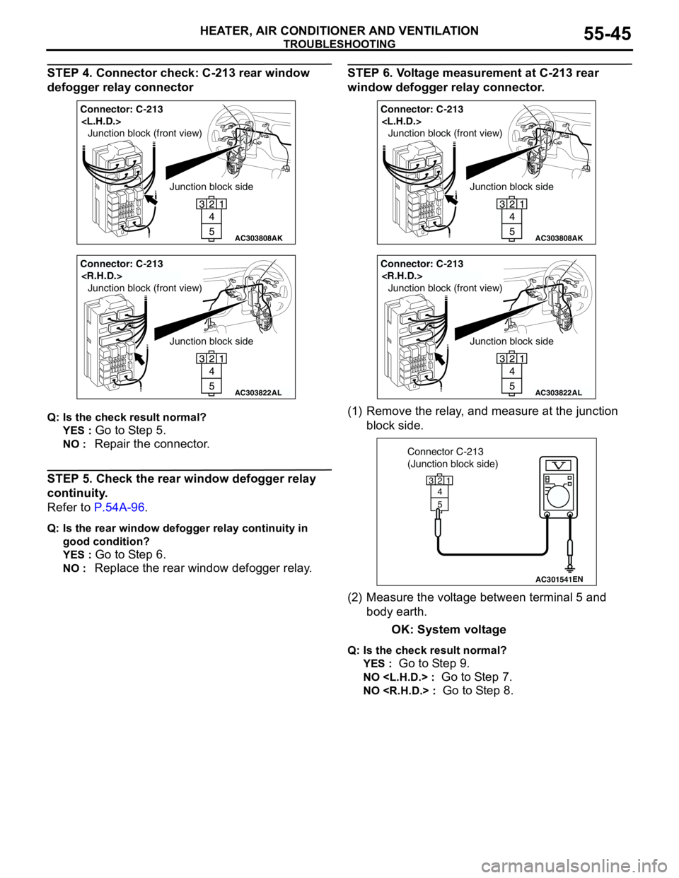
STEP 4. Connector check: C-213 rear window
defogger relay connector
Q: Is the check result normal?
YES :
Go to Step 5.
NO : Repair the connector.
STEP 5. Check the rear window defogger relay
continuity.
Refer to P.54A-96.
Q: Is the rear window defogger relay continuity in
good condition?
YES :
Go to Step 6.
NO : Replace the rear window defogger relay.
STEP 6. Voltage measurement at C-213 rear
window defogger relay connector.
(1) Remove the relay, and measure at the junction
block side.
(2) Measure the voltage between terminal 5 and
body earth.
OK: System voltage
Q: Is the check result normal?
YES :
Go to Step 9.
NO
NO
AC303808
Junction block side Junction block (front view)
Connector: C-213
AK
AC303822
Junction block side Junction block (front view)
Connector: C-213
AL
AC303808
Junction block side Junction block (front view)
Connector: C-213
AK
AC303822
Junction block side Junction block (front view)
Connector: C-213
AL
AC301541EN
Connector C-213
(Junction block side)
3
4
5
12
Page 538 of 788
TROUBLESHOOTING
HEATER, AIR CONDITIONER AND VENTILATION55-54
DIAGNOSIS
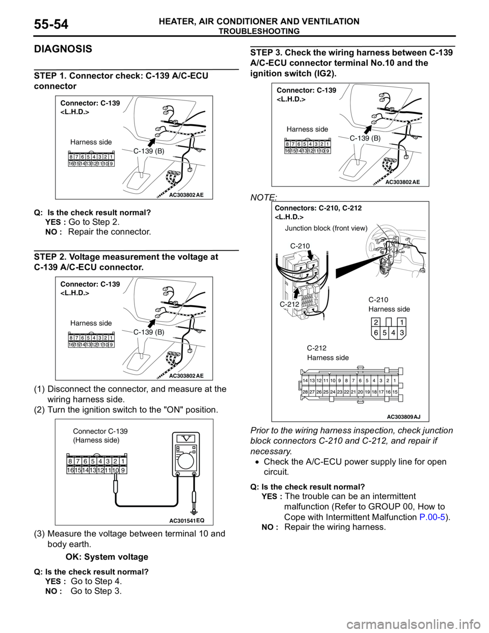
STEP 1. Connector check: C-139 A/C-ECU
connector
Q: Is the check result normal?
YES :
Go to Step 2.
NO : Repair the connector.
STEP 2. Voltage measurement the voltage at
C-139 A/C-ECU connector.
(1) Disconnect the connector, and measure at the
wiring harness side.
(2) Turn the ignition switch to the "ON" position.
(3) Measure the voltage between terminal 10 and
body earth.
OK: System voltage
Q: Is the check result normal?
YES :
Go to Step 4.
NO : Go to Step 3.
STEP 3. Check the wiring harness between C-139
A/C-ECU connector terminal No.10 and the
ignition switch (IG2).
NOTE:
Prior to the wiring harness inspection, check junction
block connectors C-210 and C-212, and repair if
necessary.
•Check the A/C-ECU power supply line for open
circuit.
Q: Is the check result normal?
YES :
The trouble can be an intermittent
malfunction (Refer to GROUP 00, How to
Cope with Intermittent Malfunction P.00-5).
NO : Repair the wiring harness.
AC303802
Connector: C-139
AE
C-139 (B)
Harness side
AC303802
Connector: C-139
AE
C-139 (B)
Harness side
AC301541EQ
Connector C-139
(Harness side)
9
1
1574
12
1110
23
13
5
14616
8
AC303802
Connector: C-139
AE
C-139 (B)
Harness side
AC303809
Junction block (front view)
Connectors: C-210, C-212
C-210
Harness side
C-212
C-210
AJ
C-212
Harness side
Page 539 of 788
TROUBLESHOOTING
HEATER, AIR CONDITIONER AND VENTILATION55-55
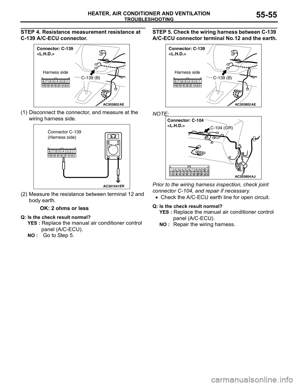
STEP 4. Resistance measurement resistance at
C-139 A/C-ECU connector.
(1) Disconnect the connector, and measure at the
wiring harness side.
(2) Measure the resistance between terminal 12 and
body earth.
OK: 2 ohms or less
Q: Is the check result normal?
YES :
Replace the manual air conditioner control
panel (A/C-ECU).
NO : Go to Step 5.
STEP 5. Check the wiring harness between C-139
A/C-ECU connector terminal No.12 and the earth.
NOTE:
Prior to the wiring harness inspection, check joint
connector C-104, and repair if necessary.
•Check the A/C-ECU earth line for open circuit.
Q: Is the check result normal?
YES :
Replace the manual air conditioner control
panel (A/C-ECU).
NO : Repair the wiring harness.
AC303802
Connector: C-139
AE
C-139 (B)
Harness side
AC301541ER
Connector C-139
(Harness side)
91
1574
12111023135146168
AC303802
Connector: C-139
AE
C-139 (B)
Harness side
AC303804
Connector: C-104
AJ
C-104 (GR)
Page 541 of 788
TROUBLESHOOTING
HEATER, AIR CONDITIONER AND VENTILATION55-57
DIAGNOSIS
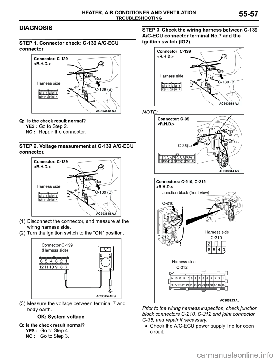
STEP 1. Connector check: C-139 A/C-ECU
connector
Q: Is the check result normal?
YES :
Go to Step 2.
NO : Repair the connector.
STEP 2. Voltage measurement at C-139 A/C-ECU
connector.
(1) Disconnect the connector, and measure at the
wiring harness side.
(2) Turn the ignition switch to the "ON" position.
(3) Measure the voltage between terminal 7 and
body earth.
OK: System voltage
Q: Is the check result normal?
YES :
Go to Step 4.
NO : Go to Step 3.
STEP 3. Check the wiring harness between C-139
A/C-ECU connector terminal No.7 and the
ignition switch (IG2).
NOTE:
Prior to the wiring harness inspection, check junction
block connectors C-210, C-212 and joint connector
C-35, and repair if necessary.
•Check the A/C-ECU power supply line for open
circuit.
AC303818
Connector: C-139
AJ
Harness side
C-139 (B)
11 12657 8 9 103 421
AC303818
Connector: C-139
AJ
Harness side
C-139 (B)
11 12657 8 9 103 421
AC301541ES
Connector C-139
(Harness side)
11 12
65
7 8 9 10
3 421
AC303818
Connector: C-139
AJ
Harness side
C-139 (B)
11 12657 8 9 103 421
AC303814
Connector: C-35
AS
C-35(L)
AC303823
Junction block (front view)
Connectors: C-210, C-212
C-210 Harness side
C-212
C-210
AJ
C-212
Harness side
Page 542 of 788
TROUBLESHOOTING
HEATER, AIR CONDITIONER AND VENTILATION55-58
Q: Is the check result normal?
YES :
The trouble can be an intermittent
malfunction (Refer to GROUP 00, How to
Cope with Intermittent Malfunction P.00-5).
NO : Repair the wiring harness.
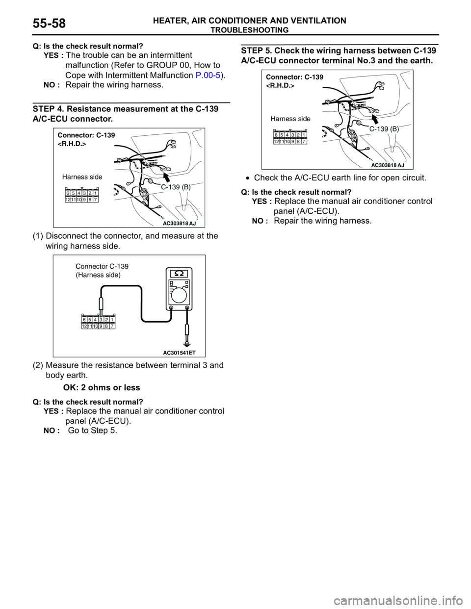
STEP 4. Resistance measurement at the C-139
A/C-ECU connector.
(1) Disconnect the connector, and measure at the
wiring harness side.
(2) Measure the resistance between terminal 3 and
body earth.
OK: 2 ohms or less
Q: Is the check result normal?
YES :
Replace the manual air conditioner control
panel (A/C-ECU).
NO : Go to Step 5.
STEP 5. Check the wiring harness between C-139
A/C-ECU connector terminal No.3 and the earth.
•Check the A/C-ECU earth line for open circuit.
Q: Is the check result normal?
YES :
Replace the manual air conditioner control
panel (A/C-ECU).
NO : Repair the wiring harness.AC303818
Connector: C-139
AJ
Harness side
C-139 (B)
11 12657 8 9 103 421
AC301541ET
Connector C-139
(Harness side)
11 12657 8 9 103 421
AC303818
Connector: C-139
AJ
Harness side
C-139 (B)
11 12657 8 9 103 421
Page 544 of 788
TROUBLESHOOTING
HEATER, AIR CONDITIONER AND VENTILATION55-60
COMMENTS ON TROUBLE SYMPTOM
If the power is not supplied to the A/C compressor,
the A/C compressor circuit system may be
defective..
TROUBLESHOOTING HINTS
•Malfunction of the A/C compressor relay
•Damaged the wiring harness or connectors
DIAGNOSIS
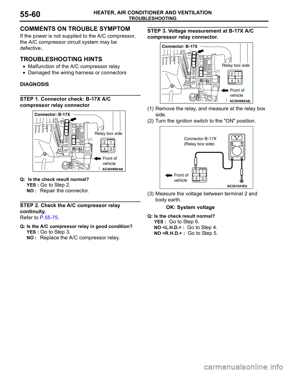
STEP 1. Connector check: B-17X A/C
compressor relay connector
Q: Is the check result normal?
YES :
Go to Step 2.
NO : Repair the connector.
STEP 2. Check the A/C compressor relay
continuity.
Refer to P.55-75.
Q: Is the A/C compressor relay in good condition?
YES :
Go to Step 3.
NO : Replace the A/C compressor relay.
STEP 3. Voltage measurement at B-17X A/C
compressor relay connector.
(1) Remove the relay, and measure at the relay box
side.
(2) Turn the ignition switch to the "ON" position.
(3) Measure the voltage between terminal 2 and
body earth.
OK: System voltage
Q: Is the check result normal?
YES :
Go to Step 6.
NO
NO
AC304988AB
Connector: B-17X
Front of
vehicle
1
3 2
4
Relay box side
AC304988AB
Connector: B-17X
Front of
vehicle
1
3 2
4
Relay box side
AC301541EU
Connector B-17X
(Relay box side)
Front of
vehicle1
3 2
4
Page 547 of 788
TROUBLESHOOTING
HEATER, AIR CONDITIONER AND VENTILATION55-63
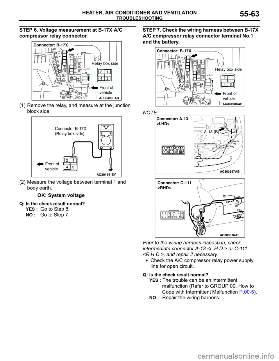
STEP 6. Voltage measurement at B-17X A/C
compressor relay connector.
(1) Remove the relay, and measure at the junction
block side.
(2) Measure the voltage between terminal 1 and
body earth.
OK: System voltage
Q: Is the check result normal?
YES :
Go to Step 8.
NO : Go to Step 7.
STEP 7. Check the wiring harness between B-17X
A/C compressor relay connector terminal No.1
and the battery.
NOTE:
Prior to the wiring harness inspection, check
intermediate connector A-13
•Check the A/C compressor relay power supply
line for open circuit.
Q: Is the check result normal?
YES :
The trouble can be an intermittent
malfunction (Refer to GROUP 00, How to
Cope with Intermittent Malfunction P.00-5).
NO : Repair the wiring harness.
AC304988AB
Connector: B-17X
Front of
vehicle
1
3 2
4
Relay box side
AC301541EV
Connector B-17X
(Relay box side)
Front of
vehicle1
3 2
4
AC304988AB
Connector: B-17X
Front of
vehicle
1
3 2
4
Relay box side
AC303857
Connector: A-13
AB
A-13 (B)
AC303816
Connector: C-111
AF
615
121179
810234
Page 592 of 788
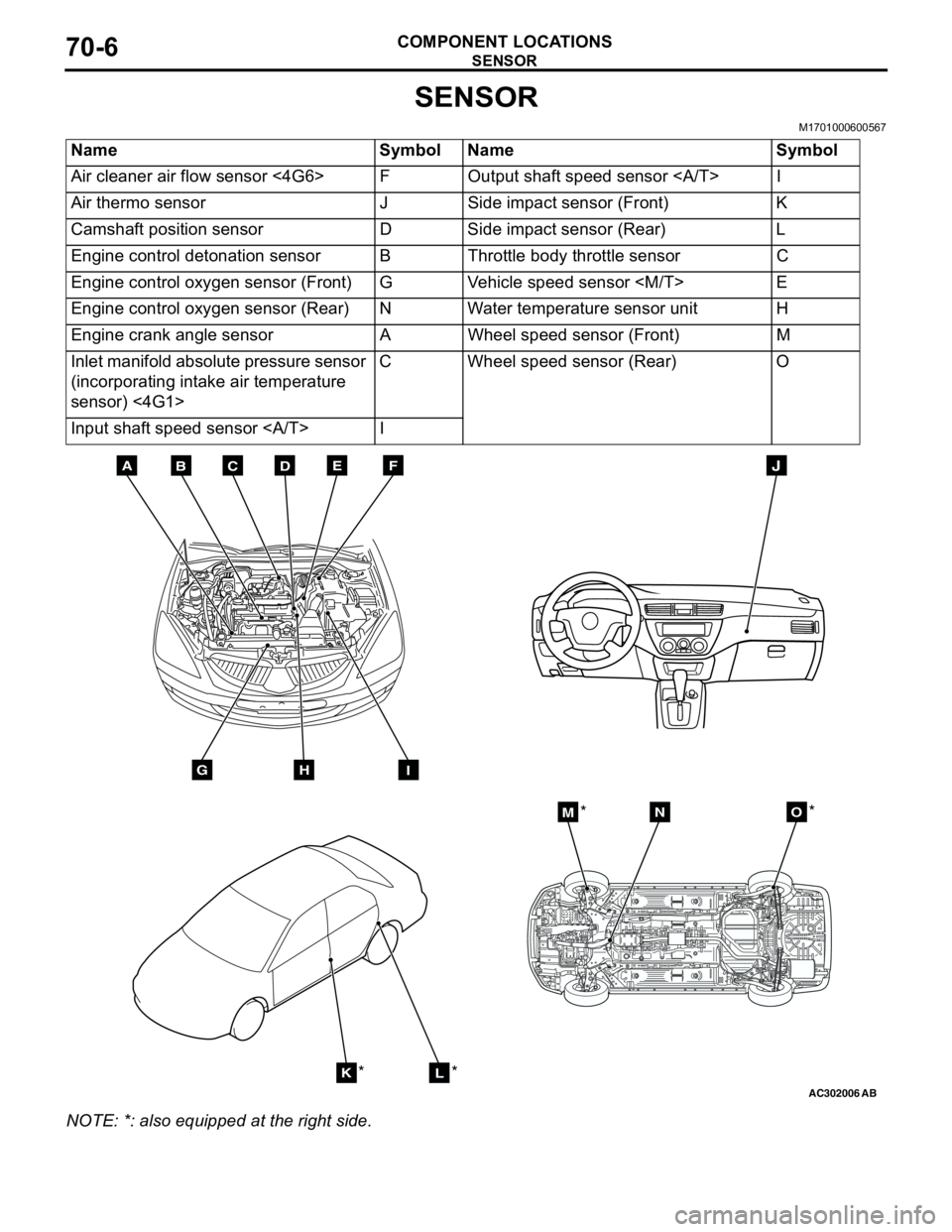
SENSOR
COMPONENT LOCATIONS70-6
SENSOR
M1701000600567
NOTE: *: also equipped at the right side.Name Symbol Name Symbol
Air cleaner air flow sensor <4G6> F Output shaft speed sensor I
Air thermo sensor J Side impact sensor (Front) K
Camshaft position sensor D Side impact sensor (Rear) L
Engine control detonation sensor B Throttle body throttle sensor C
Engine control oxygen sensor (Front) G Vehicle speed sensor
Engine control oxygen sensor (Rear) N Water temperature sensor unit H
Engine crank angle sensor A Wheel speed sensor (Front) M
Inlet manifold absolute pressure sensor
(incorporating intake air temperature
sensor) <4G1>C Wheel speed sensor (Rear) O
Input shaft speed sensor I
AC302006AB
BDCFEA
GHI
J
KL
MNO
*
***
Page 593 of 788
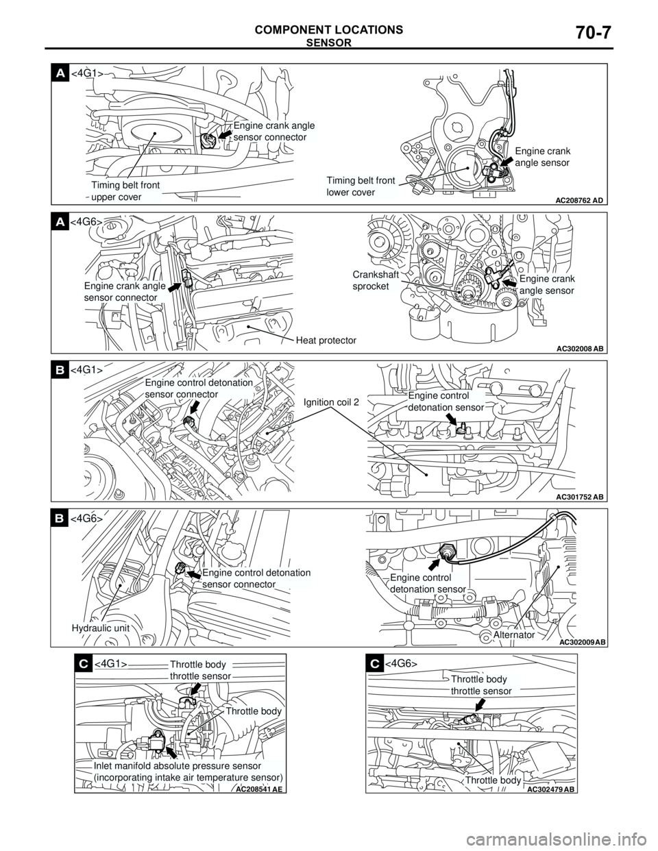
SENSOR
COMPONENT LOCATIONS70-7
AC208762
A
AD
Timing belt front
upper coverTiming belt front
lower coverEngine crank
angle sensor
<4G1>
Engine crank angle
sensor connector
AC302008
A<4G6>
ABHeat protector
Crankshaft
sprocket
Engine crank angle
sensor connectorEngine crank
angle sensor
AC301752
B
AB
Ignition coil 2
<4G1>
Engine control detonation
sensor connector
Engine control
detonation sensor
AC302009
B
AB
Hydraulic unit
<4G6>
Alternator
Engine control detonation
sensor connectorEngine control
detonation sensor
AC208541
C
AE
<4G1>
Throttle body
Throttle body
throttle sensor
Inlet manifold absolute pressure sensor
(incorporating intake air temperature sensor)
AC302479
AB
C
Throttle body
<4G6>
Throttle body
throttle sensor