Body MITSUBISHI LANCER 2005 Workshop Manual
[x] Cancel search | Manufacturer: MITSUBISHI, Model Year: 2005, Model line: LANCER, Model: MITSUBISHI LANCER 2005Pages: 788, PDF Size: 45.98 MB
Page 597 of 788
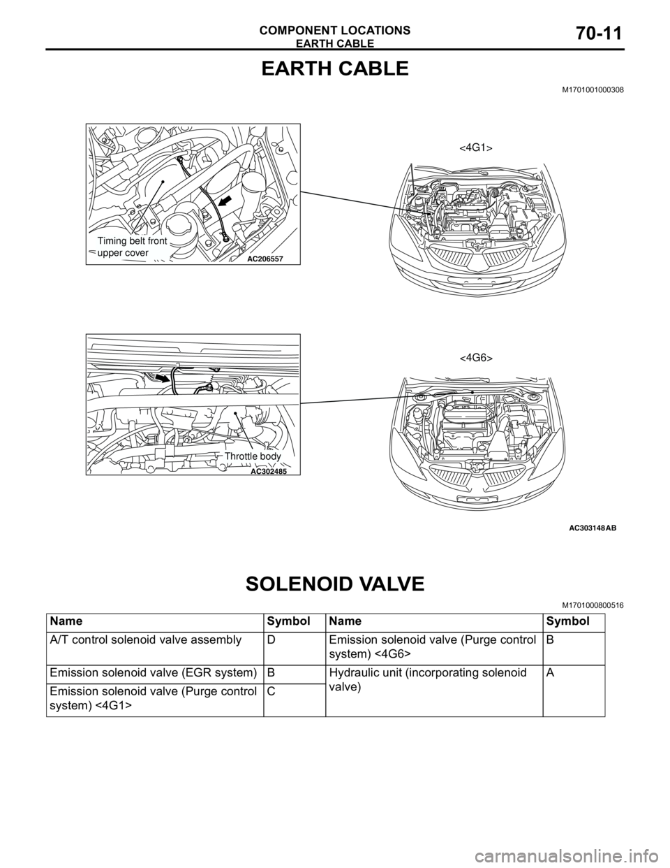
EARTH CABLE
COMPONENT LOCATIONS70-11
EARTH CABLE
M1701001000308
SOLENOID VALVE
M1701000800516
AC303148
AC206557
AC302485
AB
Timing belt front
upper cover
Throttle body
<4G1>
<4G6>
Name Symbol Name Symbol
A/T control solenoid valve assembly D Emission solenoid valve (Purge control
system) <4G6>B
Emission solenoid valve (EGR system) B Hydraulic unit (incorporating solenoid
valve)A
Emission solenoid valve (Purge control
system) <4G1>C
Page 614 of 788
ENGINE AND TRANSMISSION
CONFIGURATION DIAGRAMS80-8
ENGINE AND TRANSMISSION
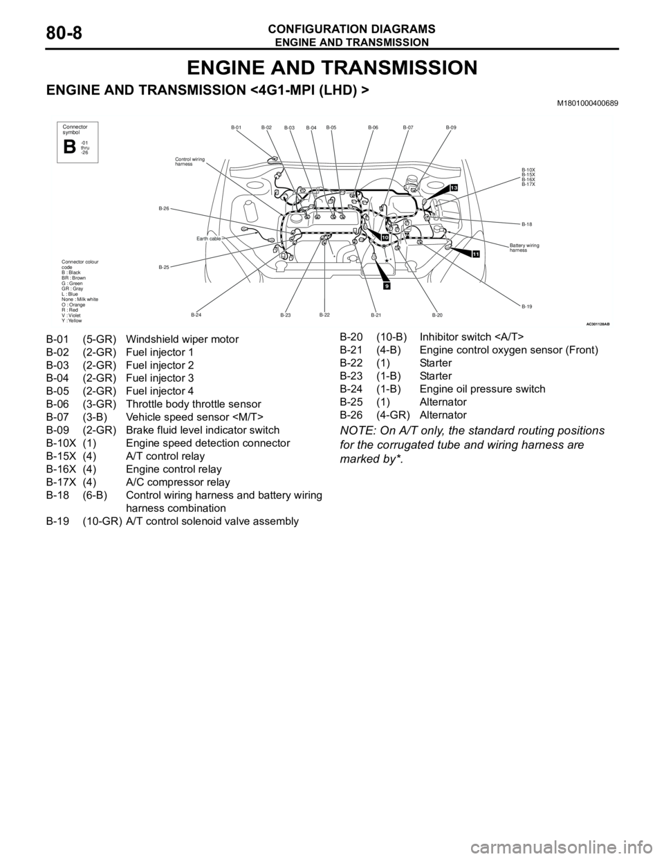
ENGINE AND TRANSMISSION <4G1-MPI (LHD) >M1801000400689
NOTE: On A/T only, the standard routing positions
for the corrugated tube and wiring harness are
marked by*.
AC301128
B-02
B-03B-04B-05
B-22
B-23 B-24 B-25 B-26Control wiring
harnessB-01
Connector colour
code
B : Black
BR : Brown
G : Green
GR : Gray
L : Blue
None : Milk white
O : Orange
R : Red
V : Violet
Y : Yellow*
Connector
symbol
-01
thru
-26B
Earth cable
AB
9
10
11
13
B-06B-07
B-09
B-10X
B-15X
B-16X
B-17X
B-18
Battery wiring
harness
B-19
B-20
B-21
*
B-01 (5-GR) Windshield wiper motor
B-02 (2-GR) Fuel injector 1
B-03 (2-GR) Fuel injector 2
B-04 (2-GR) Fuel injector 3
B-05 (2-GR) Fuel injector 4
B-06 (3-GR) Throttle body throttle sensor
B-07 (3-B) Vehicle speed sensor
B-09 (2-GR) Brake fluid level indicator switch
B-10X (1) Engine speed detection connector
B-15X (4) A/T control relay
B-16X (4) Engine control relay
B-17X (4) A/C compressor relay
B-18 (6-B) Control wiring harness and battery wiring
harness combination
B-19 (10-GR) A/T control solenoid valve assemblyB-20 (10-B) Inhibitor switch
B-21 (4-B) Engine control oxygen sensor (Front)
B-22 (1) Starter
B-23 (1-B) Starter
B-24 (1-B) Engine oil pressure switch
B-25 (1) Alternator
B-26 (4-GR) Alternator
Page 615 of 788
ENGINE AND TRANSMISSION
CONFIGURATION DIAGRAMS80-9
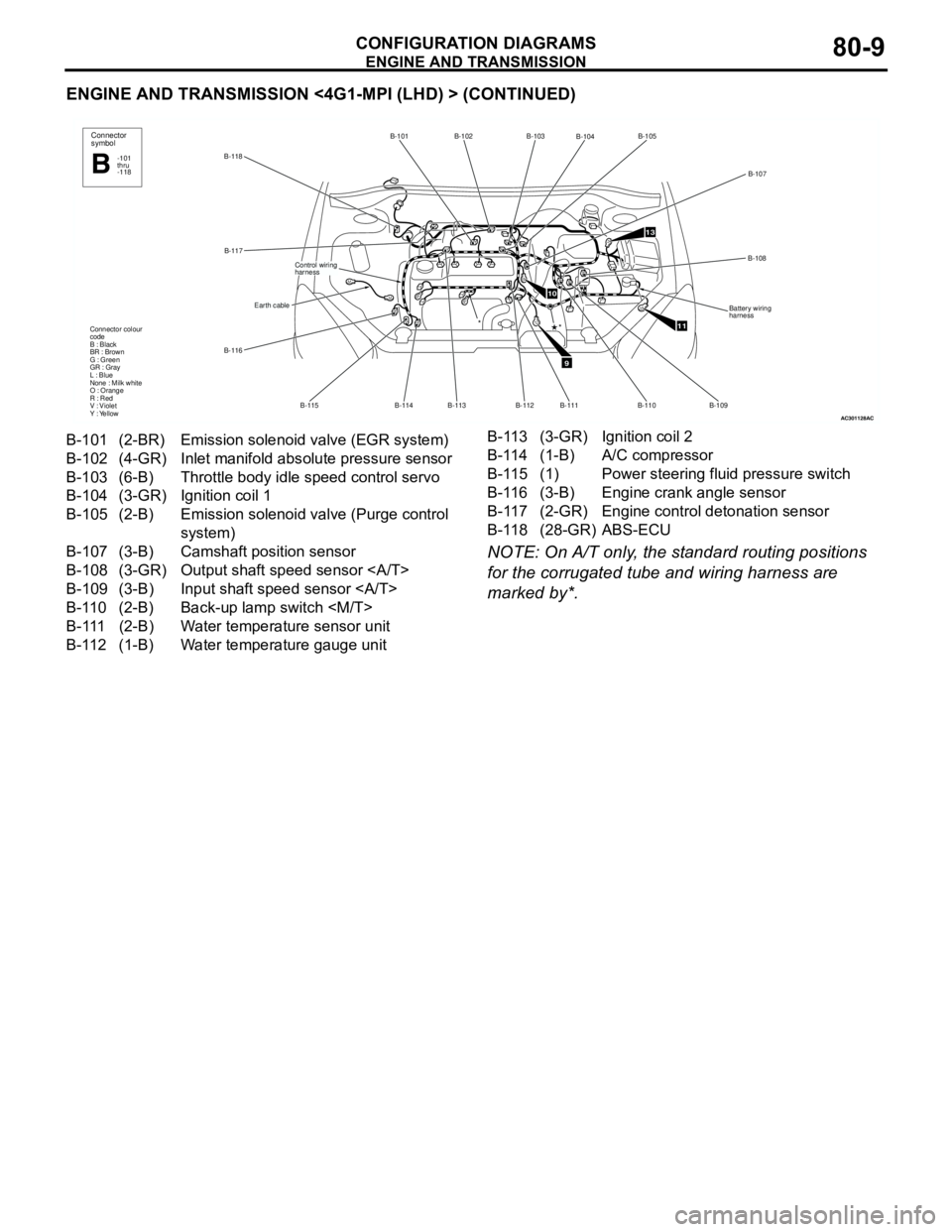
ENGINE AND TRANSMISSION <4G1-MPI (LHD) > (CONTINUED)
NOTE: On A/T only, the standard routing positions
for the corrugated tube and wiring harness are
marked by*.
AC301128
B-118B-101 B-102
B-113
B-114 B-115 B-116B-117
Earth cable
Control wiring
harness
Connector colour
code
B : Black
BR : Brown
G : Green
GR : Gray
L : Blue
None : Milk white
O : Orange
R : Red
V : Violet
Y : Yellow
Connector
symbol
-101
thru
-118B
*
AC
9
10
11
13
B-103
B-104B-105
B-107
B-108
Battery wiring
harness
B-109
B-110 B-111
*
B-112
B-101 (2-BR) Emission solenoid valve (EGR system)
B-102 (4-GR) Inlet manifold absolute pressure sensor
B-103 (6-B) Throttle body idle speed control servo
B-104 (3-GR) Ignition coil 1
B-105 (2-B) Emission solenoid valve (Purge control
system)
B-107 (3-B) Camshaft position sensor
B-108 (3-GR) Output shaft speed sensor
B-109 (3-B) Input shaft speed sensor
B-110 (2-B) Back-up lamp switch
B-111 (2-B) Water temperature sensor unit
B-112 (1-B) Water temperature gauge unitB-113 (3-GR) Ignition coil 2
B-114 (1-B) A/C compressor
B-115 (1) Power steering fluid pressure switch
B-116 (3-B) Engine crank angle sensor
B-117 (2-GR) Engine control detonation sensor
B-118 (28-GR) ABS-ECU
Page 616 of 788
ENGINE AND TRANSMISSION
CONFIGURATION DIAGRAMS80-10
ENGINE AND TRANSMISSION
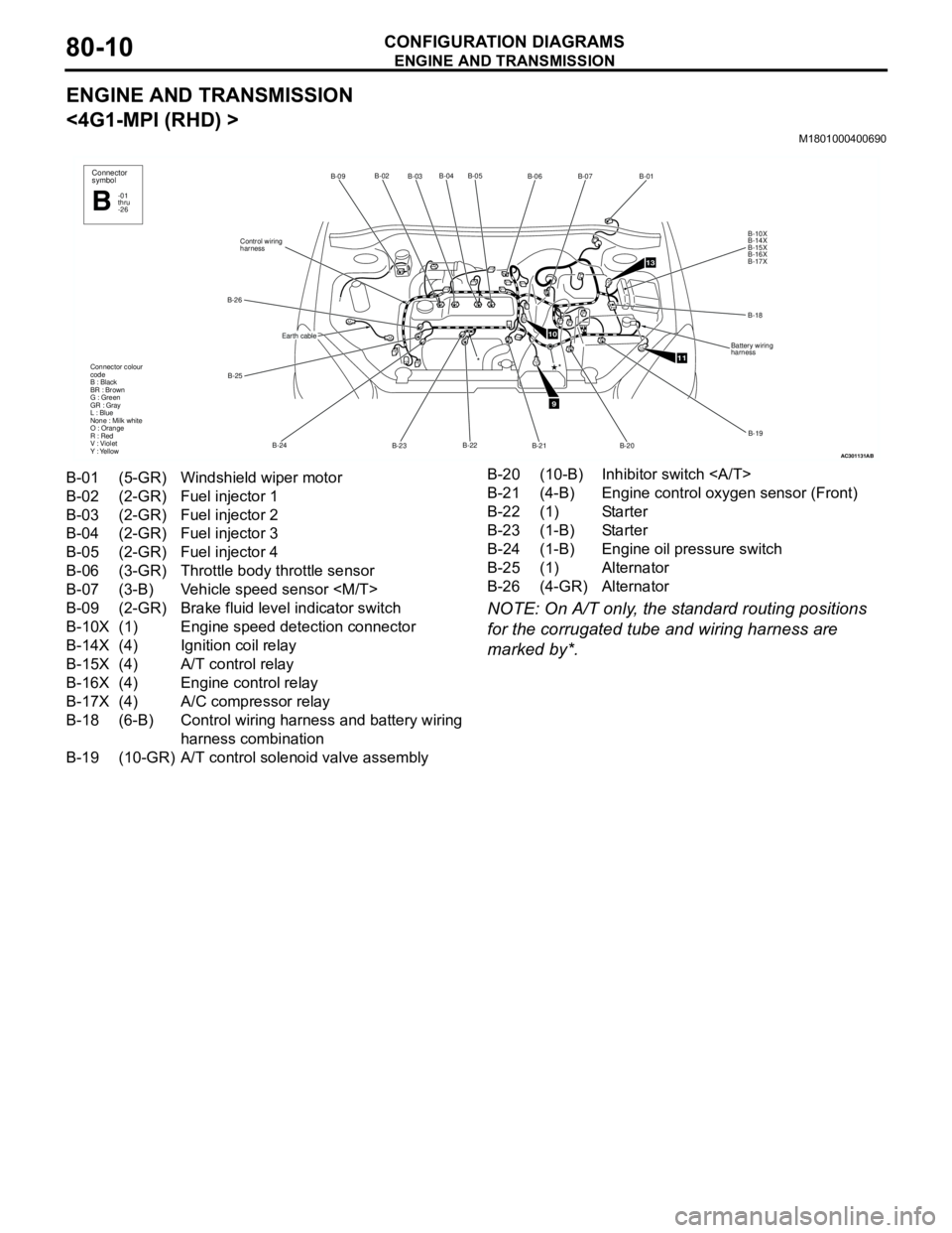
<4G1-MPI (RHD) >
M1801000400690
NOTE: On A/T only, the standard routing positions
for the corrugated tube and wiring harness are
marked by*.
AC301131
B-02
B-03B-04 B-05
B-22
B-23 B-24 B-25 B-26Control wiring
harnessB-09
Connector colour
code
B : Black
BR : Brown
G : Green
GR : Gray
L : Blue
None : Milk white
O : Orange
R : Red
V : Violet
Y : Yellow*
Connector
symbol
-01
thru
-26B
Earth cable
AB
9
10
11
13
B-06B-07
B-01
B-10X
B-14X
B-15X
B-16X
B-17X
B-18
Battery wiring
harness
B-19
B-20 B-21
*
B-01 (5-GR) Windshield wiper motor
B-02 (2-GR) Fuel injector 1
B-03 (2-GR) Fuel injector 2
B-04 (2-GR) Fuel injector 3
B-05 (2-GR) Fuel injector 4
B-06 (3-GR) Throttle body throttle sensor
B-07 (3-B) Vehicle speed sensor
B-09 (2-GR) Brake fluid level indicator switch
B-10X (1) Engine speed detection connector
B-14X (4) Ignition coil relay
B-15X (4) A/T control relay
B-16X (4) Engine control relay
B-17X (4) A/C compressor relay
B-18 (6-B) Control wiring harness and battery wiring
harness combination
B-19 (10-GR) A/T control solenoid valve assemblyB-20 (10-B) Inhibitor switch
B-21 (4-B) Engine control oxygen sensor (Front)
B-22 (1) Starter
B-23 (1-B) Starter
B-24 (1-B) Engine oil pressure switch
B-25 (1) Alternator
B-26 (4-GR) Alternator
Page 617 of 788

ENGINE AND TRANSMISSION
CONFIGURATION DIAGRAMS80-11
ENGINE AND TRANSMISSION <4G1-MPI (RHD) > (CONTINUED)
NOTE: On A/T only, the standard routing positions
for the corrugated tube and wiring harness are
marked by*.
AC301131
B-117B-101 B-102
B-113 B-114 B-115 B-116
Earth cable
Control wiring
harness
Connector colour
code
B : Black
BR : Brown
G : Green
GR : Gray
L : Blue
None : Milk white
O : Orange
R : Red
V : Violet
Y : Yellow
Connector
symbol
-101
thru
-118B
*
AC
9
10
11
13
B-103
B-104B-105
B-107
B-108
Battery wiring
harness
B-109 B-110 B-111
*
B-112
B-118
B-101 (2-BR) Emission solenoid valve (EGR system)
B-102 (4-GR) Inlet manifold absolute pressure sensor
B-103 (6-B) Throttle body idle speed control servo
B-104 (3-GR) Ignition coil 1
B-105 (2-B) Emission solenoid valve (Purge control
system)
B-107 (3-B) Camshaft position sensor
B-108 (3-GR) Output shaft speed sensor
B-109 (3-B) Input shaft speed sensor
B-110 (2-B) Back-up lamp switch
B-111 (2-B) Water temperature sensor unit
B-112 (1-B) Water temperature gauge unitB-113 (3-GR) Ignition coil 2
B-114 (1-B) A/C compressor
B-115 (1) Power steering fluid pressure switch
B-116 (3-B) Engine crank angle sensor
B-117 (2-GR) Engine control detonation sensor
B-118 (28-GR) ABS-ECU
Page 618 of 788
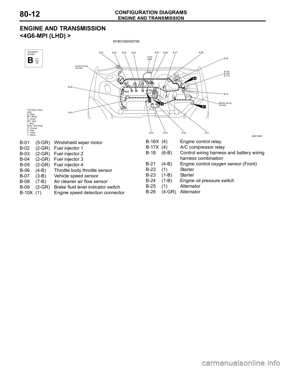
ENGINE AND TRANSMISSION
CONFIGURATION DIAGRAMS80-12
ENGINE AND TRANSMISSION
<4G6-MPI (LHD) >
M1801000400708
AC301134
B-02
B-03B-04
B-25 B-26Control wiring
harnessB-01
Connector colour
code
B : Black
BR : Brown
G : Green
GR : Gray
L : Blue
None : Milk white
O : Orange
R : Red
V : Violet
Y : YellowConnector
symbol
-01
thru
-26B
AB
910
11
13
B-06B-07
B-09
B-10X
B-16X
B-17X
B-18
Battery wiring
harness
B-21 B-22
B-23B-05B-08
B-24
Earth
cable
B-01 (5-GR) Windshield wiper motor
B-02 (2-GR) Fuel injector 1
B-03 (2-GR) Fuel injector 2
B-04 (2-GR) Fuel injector 3
B-05 (2-GR) Fuel injector 4
B-06 (4-B) Throttle body throttle sensor
B-07 (3-B) Vehicle speed sensor
B-08 (7-B) Air cleaner air flow sensor
B-09 (2-GR) Brake fluid level indicator switch
B-10X (1) Engine speed detection connectorB-16X (4) Engine control relay
B-17X (4) A/C compressor relay
B-18 (6-B) Control wiring harness and battery wiring
harness combination
B-21 (4-B) Engine control oxygen sensor (Front)
B-22 (1) Starter
B-23 (1-B) Starter
B-24 (1-B) Engine oil pressure switch
B-25 (1) Alternator
B-26 (4-GR) Alternator
Page 619 of 788
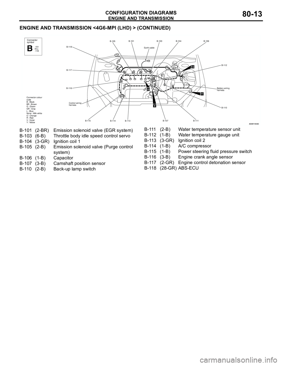
ENGINE AND TRANSMISSION
CONFIGURATION DIAGRAMS80-13
ENGINE AND TRANSMISSION <4G6-MPI (LHD) > (CONTINUED)
AC301134
B-118B-101
B-114 B-115 B-116B-117
Control wiring
harness Connector colour
code
B : Black
BR : Brown
G : Green
GR : Gray
L : Blue
None : Milk white
O : Orange
R : Red
V : Violet
Y : Yellow
B-113
B-105Connector
symbol
-101
thru
-118B
AC
9
10
11
13
B-103B-104B-106
B-112
B-110 Battery wiring
harness
B-111
B-107
Earth cable
B-101 (2-BR) Emission solenoid valve (EGR system)
B-103 (6-B) Throttle body idle speed control servo
B-104 (3-GR) Ignition coil 1
B-105 (2-B) Emission solenoid valve (Purge control
system)
B-106 (1-B) Capacitor
B-107 (3-B) Camshaft position sensor
B-110 (2-B) Back-up lamp switch B-111 (2-B) Water temperature sensor unit
B-112 (1-B) Water temperature gauge unit
B-113 (3-GR) Ignition coil 2
B-114 (1-B) A/C compressor
B-115 (1-B) Power steering fluid pressure switch
B-116 (3-B) Engine crank angle sensor
B-117 (2-GR) Engine control detonation sensor
B-118 (28-GR) ABS-ECU
Page 620 of 788
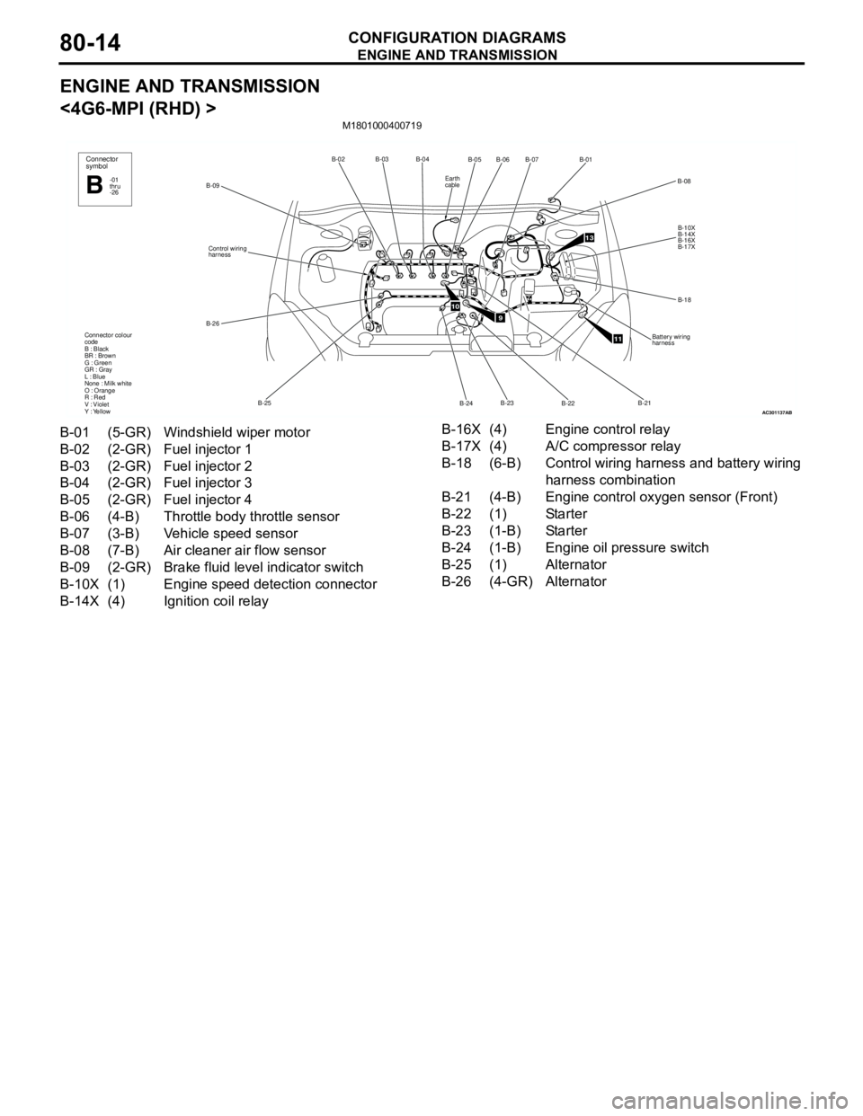
ENGINE AND TRANSMISSION
CONFIGURATION DIAGRAMS80-14
ENGINE AND TRANSMISSION
<4G6-MPI (RHD) >
M1801000400719
AC301137
B-02B-03B-04
B-25 B-26Control wiring
harness
B-09
Connector colour
code
B : Black
BR : Brown
G : Green
GR : Gray
L : Blue
None : Milk white
O : Orange
R : Red
V : Violet
Y : Yellow
Connector
symbol
-01
thru
-26B
AB
910
11
13
B-05
B-07B-01
B-10X
B-14X
B-16X
B-17X
B-18
Battery wiring
harness
B-22 B-24B-06
B-08
B-23B-21
Earth
cable
B-01 (5-GR) Windshield wiper motor
B-02 (2-GR) Fuel injector 1
B-03 (2-GR) Fuel injector 2
B-04 (2-GR) Fuel injector 3
B-05 (2-GR) Fuel injector 4
B-06 (4-B) Throttle body throttle sensor
B-07 (3-B) Vehicle speed sensor
B-08 (7-B) Air cleaner air flow sensor
B-09 (2-GR) Brake fluid level indicator switch
B-10X (1) Engine speed detection connector
B-14X (4) Ignition coil relayB-16X (4) Engine control relay
B-17X (4) A/C compressor relay
B-18 (6-B) Control wiring harness and battery wiring
harness combination
B-21 (4-B) Engine control oxygen sensor (Front)
B-22 (1) Starter
B-23 (1-B) Starter
B-24 (1-B) Engine oil pressure switch
B-25 (1) Alternator
B-26 (4-GR) Alternator
Page 621 of 788
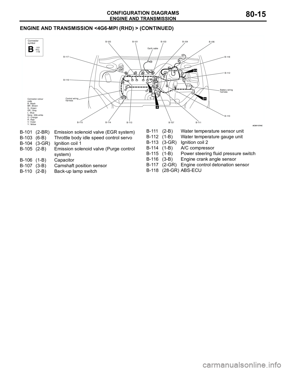
ENGINE AND TRANSMISSION
CONFIGURATION DIAGRAMS80-15
ENGINE AND TRANSMISSION <4G6-MPI (RHD) > (CONTINUED)
AC301137
B-117B-105 B-101
B-113 B-114 B-115 B-116
Control wiring
harness Connector colour
code
B : Black
BR : Brown
G : Green
GR : Gray
L : Blue
None : Milk white
O : Orange
R : Red
V : Violet
Y : Yellow
Connector
symbol
-101
thru
-118B
AC
9
11
13
B-103
B-106
B-118
B-112
Battery wiring
harness
B-110
B-111
B-107
B-104
10
Earth cable
B-101 (2-BR) Emission solenoid valve (EGR system)
B-103 (6-B) Throttle body idle speed control servo
B-104 (3-GR) Ignition coil 1
B-105 (2-B) Emission solenoid valve (Purge control
system)
B-106 (1-B) Capacitor
B-107 (3-B) Camshaft position sensor
B-110 (2-B) Back-up lamp switch B-111 (2-B) Water temperature sensor unit
B-112 (1-B) Water temperature gauge unit
B-113 (3-GR) Ignition coil 2
B-114 (1-B) A/C compressor
B-115 (1-B) Power steering fluid pressure switch
B-116 (3-B) Engine crank angle sensor
B-117 (2-GR) Engine control detonation sensor
B-118 (28-GR) ABS-ECU
Page 648 of 788

CENTRALIZED JUNCTION
CIRCUIT DIAGRAMS90-10
CENTRALIZED JUNCTION
M1901000300991
FUSIBLE LINK AND FUSE
ENGINE COMPARTMENT
No. Power supply circuit Name Rated
capacity (A)Housing
colourLoad circuit
1 Battery/ Alternator
(Fusible link No.26)Fusible
link60 Yellow Fuse No.15, 16, 19, 20 (in junction
block) circuit
2 50 Red Fan controller
3 60 Yellow ABS-ECU
4 40 Green Ignition switch circuit
5 30 Pink Power window main switch and power
window sub switch
6 Fuse 15 Blue Front fog lamp, front fog lamp
indicator lamp, front fog lamp relay
and spare connector (for front fog
lamp)
7 10 Red Horn relay and horn
8 20 Yellow Air cleaner air flow sensor, camshaft
position sensor, emission solenoid
valve (EGR system), emission
solenoid valve (purge control system),
engine-A/T-ECU, engine-ECU, engine
control oxygen sensor, engine control
relay, engine crank angle sensor, fan
control relay, fuel injector, ignition coil
relay, immobilizer-ECU and throttle
body idle speed control servo
9 10 Red A/C compressor
10 15 Blue ABS-ECU, engine-A/T-ECU, high
mount stop lamp and rear combination
lamp
11 15 Blue Accessory socket
12 7.5 Brown Alternator
13 10 Red ETACS-ECU, front turn signal lamp,
rear combination lamp, side turn
signal lamp and turn signal indicator
lamp
14 20 Yellow A/T control solenoid valve assembly
and engine-A/T-ECU
15 15 Blue Fuel pump
16 Front-ECU
(Headlamp relay: HI)10 Red Headlamp (RH)
17 10 Red Headlamp (LH) and high beam
indicator lamp
18 Front-ECU
(Headlamp relay: LO)10 Red Headlamp (RH)
19 10 Red Headlamp (LH), headlamp assembly
and headlamp levelling switch