Air con MITSUBISHI LANCER 2005 Repair Manual
[x] Cancel search | Manufacturer: MITSUBISHI, Model Year: 2005, Model line: LANCER, Model: MITSUBISHI LANCER 2005Pages: 788, PDF Size: 45.98 MB
Page 279 of 788
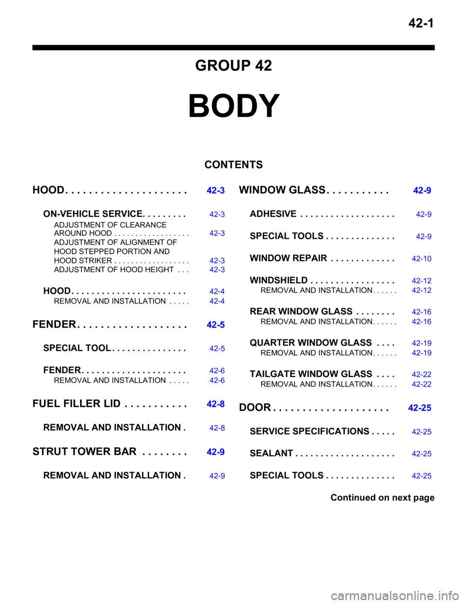
42-1
GROUP 42
BODY
CONTENTS
HOOD . . . . . . . . . . . . . . . . . . . . .
42-3
ON-VEHICLE SERVICE. . . . . . . . .
42-3
ADJUSTMENT OF CLEARANCE
AROUND HOOD . . . . . . . . . . . . . . . . . . 42-3
ADJUSTMENT OF ALIGNMENT OF
HOOD STEPPED PORTION AND
HOOD STRIKER . . . . . . . . . . . . . . . . . . 42-3
ADJUSTMENT OF HOOD HEIGHT . . . 42-3
HOOD . . . . . . . . . . . . . . . . . . . . . . .42-4
REMOVAL AND INSTALLATION . . . . . 42-4
FENDER . . . . . . . . . . . . . . . . . . .42-5
SPECIAL TOOL . . . . . . . . . . . . . . .
42-5
FENDER . . . . . . . . . . . . . . . . . . . . .42-6
REMOVAL AND INSTALLATION . . . . . 42-6
FUEL FILLER LID . . . . . . . . . . .42-8
REMOVAL AND INSTALLATION .
42-8
STRUT TOWER BAR . . . . . . . .42-9
REMOVAL AND INSTALLATION .
42-9
WINDOW GLASS . . . . . . . . . . . 42-9
ADHESIVE . . . . . . . . . . . . . . . . . . .
42-9
SPECIAL TOOLS . . . . . . . . . . . . . .42-9
WINDOW REPAIR . . . . . . . . . . . . .42-10
WINDSHIELD . . . . . . . . . . . . . . . . .42-12
REMOVAL AND INSTALLATION . . . . . . 42-12
REAR WINDOW GLASS . . . . . . . .42-16
REMOVAL AND INSTALLATION . . . . . . 42-16
QUARTER WINDOW GLASS . . . .42-19
REMOVAL AND INSTALLATION . . . . . . 42-19
TAILGATE WINDOW GLASS . . . .42-22
REMOVAL AND INSTALLATION . . . . . . 42-22
DOOR . . . . . . . . . . . . . . . . . . . . 42-25
SERVICE SPECIFICATIONS . . . . .
42-25
SEALANT . . . . . . . . . . . . . . . . . . . .42-25
SPECIAL TOOLS . . . . . . . . . . . . . .42-25
Continued on next page
Page 284 of 788
FENDER
BODY42-6
FENDER
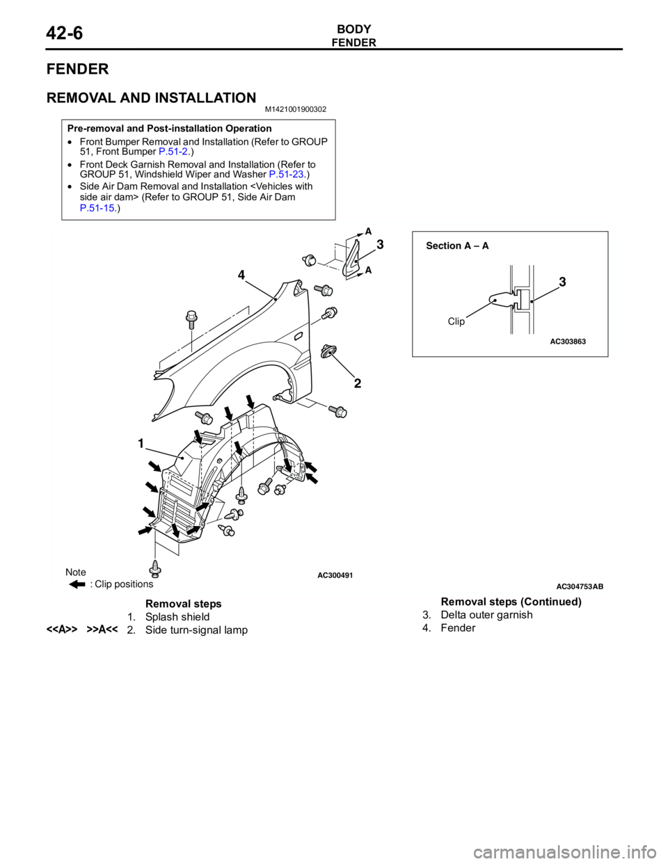
REMOVAL AND INSTALLATIONM1421001900302
Pre-removal and Post-installation Operation
•Front Bumper Removal and Installation (Refer to GROUP
51, Front Bumper P.51-2.)
•Front Deck Garnish Removal and Installation (Refer to
GROUP 51, Windshield Wiper and Washer P.51-23.)
•Side Air Dam Removal and Installation
P.51-15.)
AC300491
AC304753
AC303863
Clip Section A – A
AB
A A
123
3 4
Note
: Clip positions
Removal steps
1. Splash shield
<> >>A<<2. Side turn-signal lamp3. Delta outer garnish
4. FenderRemoval steps (Continued)
Page 306 of 788
DOOR
BODY42-28
DOOR WINDOW GLASS ADJUSTMENTM1423001000327
Check that the door glass moves while contacting
the door glass channel when it is raised and lowered
fully. If not, adjust the door window according to the
following procedures.
1. Remove the door trim assembly (Refer to GROUP
52A, Door trim P.52A-15).
2. Remove the waterproof film (Refer to P.42-39).
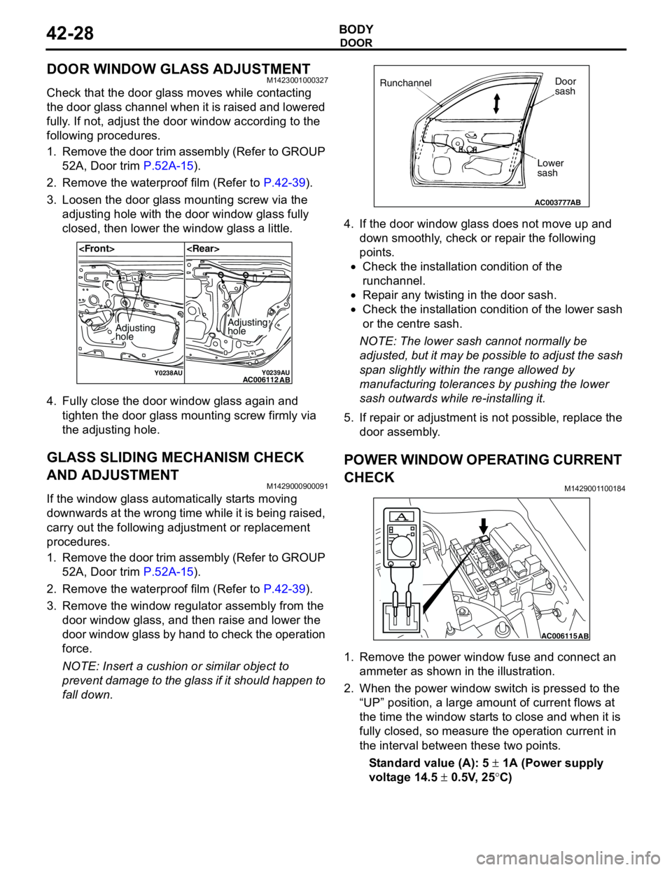
3. Loosen the door glass mounting screw via the
adjusting hole with the door window glass fully
closed, then lower the window glass a little.
4. Fully close the door window glass again and
tighten the door glass mounting screw firmly via
the adjusting hole.
GLASS SLIDING MECHANISM CHECK
AND ADJUSTMENT
M1429000900091
If the window glass automatically starts moving
downwards at the wrong time while it is being raised,
carry out the following adjustment or replacement
procedures.
1. Remove the door trim assembly (Refer to GROUP
52A, Door trim P.52A-15).
2. Remove the waterproof film (Refer to P.42-39).
3. Remove the window regulator assembly from the
door window glass, and then raise and lower the
door window glass by hand to check the operation
force.
NOTE: Insert a cushion or similar object to
prevent damage to the glass if it should happen to
fall down.4. If the door window glass does not move up and
down smoothly, check or repair the following
points.
•Check the installation condition of the
runchannel.
•Repair any twisting in the door sash.
•Check the installation condition of the lower sash
or the centre sash.
NOTE: The lower sash cannot normally be
adjusted, but it may be possible to adjust the sash
span slightly within the range allowed by
manufacturing tolerances by pushing the lower
sash outwards while re-installing it.
5. If repair or adjustment is not possible, replace the
door assembly.
POWER WINDOW OPERATING CURRENT
CHECK
M1429001100184
1. Remove the power window fuse and connect an
ammeter as shown in the illustration.
2. When the power window switch is pressed to the
“UP” position, a large amount of current flows at
the time the window starts to close and when it is
fully closed, so measure the operation current in
the interval between these two points.
Standard value (A): 5 ± 1A (Power supply
voltage 14.5 ± 0.5V, 25°C)
Y0238AUY0239AUAC006112
AB
Adjusting
holeAdjusting
hole
AC003777
RunchannelDoor
sash
Lower
sash
AB
AC006115AB
Page 339 of 788
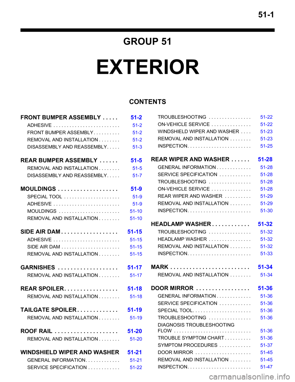
51-1
GROUP 51
EXTERIOR
CONTENTS
FRONT BUMPER ASSEMBLY . . . . .51-2
ADHESIVE . . . . . . . . . . . . . . . . . . . . . . . . . 51-2
FRONT BUMPER ASSEMBLY . . . . . . . . . . 51-2
REMOVAL AND INSTALLATION . . . . . . . . 51-2
DISASSEMBLY AND REASSEMBLY . . . . . 51-3
REAR BUMPER ASSEMBLY . . . . . .51-5
REMOVAL AND INSTALLATION . . . . . . . . 51-5
DISASSEMBLY AND REASSEMBLY . . . . . 51-7
MOULDINGS . . . . . . . . . . . . . . . . . . .51-9
SPECIAL TOOL . . . . . . . . . . . . . . . . . . . . . 51-9
ADHESIVE . . . . . . . . . . . . . . . . . . . . . . . . . 51-9
MOULDINGS . . . . . . . . . . . . . . . . . . . . . . . 51-10
REMOVAL AND INSTALLATION . . . . . . . . 51-10
SIDE AIR DAM . . . . . . . . . . . . . . . . . .51-15
ADHESIVE . . . . . . . . . . . . . . . . . . . . . . . . . 51-15
SIDE AIR DAM . . . . . . . . . . . . . . . . . . . . . . 51-15
REMOVAL AND INSTALLATION . . . . . . . . 51-15
GARNISHES . . . . . . . . . . . . . . . . . . .51-17
REMOVAL AND INSTALLATION . . . . . . . . 51-17
REAR SPOILER . . . . . . . . . . . . . . . . .51-18
REMOVAL AND INSTALLATION . . . . . . . . 51-18
TAILGATE SPOILER . . . . . . . . . . . . .51-19
REMOVAL AND INSTALLATION . . . . . . . . 51-19
ROOF RAIL . . . . . . . . . . . . . . . . . . . .51-20
REMOVAL AND INSTALLATION . . . . . . . . 51-20
WINDSHIELD WIPER AND WASHER51-21
GENERAL INFORMATION . . . . . . . . . . . . . 51-21
SERVICE SPECIFICATION . . . . . . . . . . . . 51-22TROUBLESHOOTING . . . . . . . . . . . . . . . . 51-22
ON-VEHICLE SERVICE . . . . . . . . . . . . . . . 51-22
WINDSHIELD WIPER AND WASHER . . . . 51-23
REMOVAL AND INSTALLATION . . . . . . . . 51-23
INSPECTION . . . . . . . . . . . . . . . . . . . . . . . . 51-25
REAR WIPER AND WASHER . . . . . .51-28
GENERAL INFORMATION . . . . . . . . . . . . . 51-28
SERVICE SPECIFICATION . . . . . . . . . . . . 51-28
TROUBLESHOOTING . . . . . . . . . . . . . . . . 51-28
ON-VEHICLE SERVICE . . . . . . . . . . . . . . . 51-28
REAR WIPER AND WASHER . . . . . . . . . . 51-29
REMOVAL AND INSTALLATION . . . . . . . . 51-29
INSPECTION . . . . . . . . . . . . . . . . . . . . . . . . 51-30
HEADLAMP WASHER . . . . . . . . . . . .51-32
TROUBLESHOOTING . . . . . . . . . . . . . . . . 51-32
HEADLAMP WASHER . . . . . . . . . . . . . . . . 51-32
REMOVAL AND INSTALLATION . . . . . . . . 51-32
INSPECTION . . . . . . . . . . . . . . . . . . . . . . . . 51-33
MARK . . . . . . . . . . . . . . . . . . . . . . . . .51-34
REMOVAL AND INSTALLATION . . . . . . . . 51-34
DOOR MIRROR . . . . . . . . . . . . . . . . .51-36
GENERAL INFORMATION . . . . . . . . . . . . . 51-36
SERVICE SPECIFICATION . . . . . . . . . . . . 51-36
SPECIAL TOOL. . . . . . . . . . . . . . . . . . . . . . 51-36
TROUBLESHOOTING . . . . . . . . . . . . . . . . 51-36
DIAGNOSIS TROUBLESHOOTING
FLOW . . . . . . . . . . . . . . . . . . . . . . . . . . . . . 51-36
TROUBLE SYMPTOM CHART . . . . . . . . . . 51-36
SYMPTOM PROCEDURES . . . . . . . . . . . . 51-37
DOOR MIRROR . . . . . . . . . . . . . . . . . . . . . 51-45
REMOVAL AND INSTALLATION . . . . . . . . 51-45
INSPECTION . . . . . . . . . . . . . . . . . . . . . . . . 51-47
Page 341 of 788
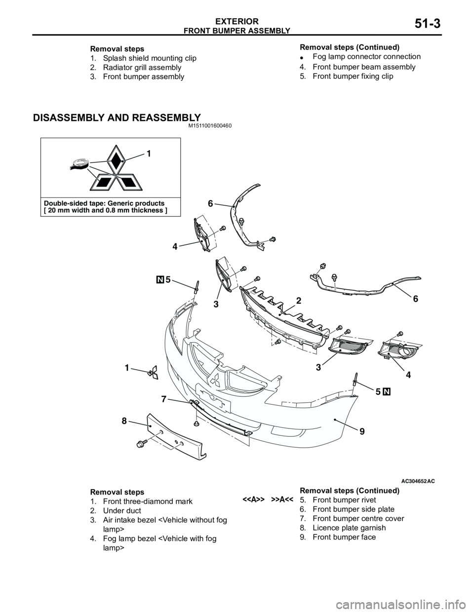
FRONT BUMPER ASSEMBLY
EXTERIOR51-3
DISASSEMBLY AND REASSEMBLYM1511001600460
Removal steps
1. Splash shield mounting clip
2. Radiator grill assembly
3. Front bumper assembly•Fog lamp connector connection
4. Front bumper beam assembly
5. Front bumper fixing clip Removal steps (Continued)
AC304652AC
Double-sided tape: Generic products
[ 20 mm width and 0.8 mm thickness ]
1
1
8
7
9
6
6
5
5
3
4
34
N
N
2
Removal steps
1. Front three-diamond mark
2. Under duct
3. Air intake bezel
4. Fog lamp bezel
6. Front bumper side plate
7. Front bumper centre cover
8. Licence plate garnish
9. Front bumper face Removal steps (Continued)
Page 376 of 788
DOOR MIRROR
EXTERIOR51-38
COMMENTS ON TROUBLE SYMPTOM
The heated door mirrors should works for
approximately 11 minutes when the rear defogger
switch is turned on. If the mirror heater does not work
for the specified period, the defogger relay circuit
(heated door mirror power supply circuit) may be
defective.
Possible causes
•Damaged harness wires and connectors
DIAGNOSIS PROCEDURE
STEP 1. Check the rear window defogger.
Check that the rear window defogger system should
work normally.
Q: Is the check result normal?
YES :
Go to Step 2.
NO : Troubleshoot the rear window defogger
(Refer to GROUP 55,
TroubleshootingP.55-42).
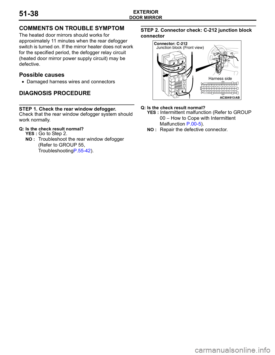
STEP 2. Connector check: C-212 junction block
connector
Q: Is the check result normal?
YES :
Intermittent malfunction (Refer to GROUP
00 − How to Cope with Intermittent
Malfunction P.00-5).
NO : Repair the defective connector.
AC304913
21716151718 201912345 623 222425282627981011141213
Connector: C-212
Harness side
AB
Junction block (Front view)
Page 378 of 788
DOOR MIRROR
EXTERIOR51-40
COMMENTS ON TROUBLE SYMPTOM
If either of the heated door mirrors does not work, the
door mirror assembly may be defective.
Possible causes
•Malfunction of the door mirror assembly
•Damaged harness wires and connectors
DIAGNOSIS PROCEDURE
Step 1. Verify the operation of each heated door
mirror.
Q: Which door mirror does not heat?
Door mirror (RH) :
Go to Step 2.
Door mirror (LH) : Go to Step 9.
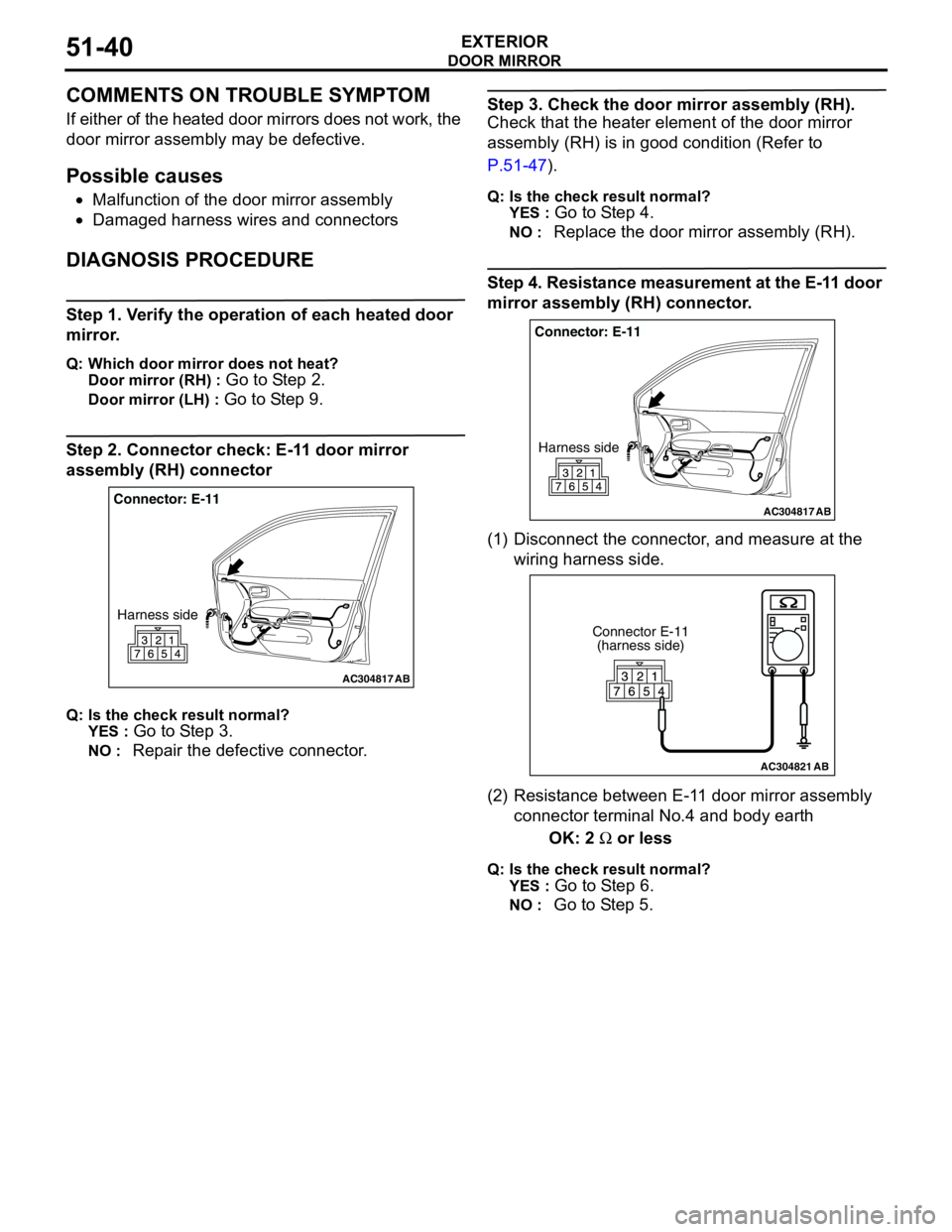
Step 2. Connector check: E-11 door mirror
assembly (RH) connector
Q: Is the check result normal?
YES :
Go to Step 3.
NO : Repair the defective connector.
Step 3. Check the door mirror assembly (RH).
Check that the heater element of the door mirror
assembly (RH) is in good condition (Refer to
P.51-47).
Q: Is the check result normal?
YES :
Go to Step 4.
NO : Replace the door mirror assembly (RH).
Step 4. Resistance measurement at the E-11 door
mirror assembly (RH) connector.
(1) Disconnect the connector, and measure at the
wiring harness side.
(2) Resistance between E-11 door mirror assembly
connector terminal No.4 and body earth
OK: 2 Ω or less
Q: Is the check result normal?
YES :
Go to Step 6.
NO : Go to Step 5.
AC304817
Connector: E-11
Harness side
AB
AC304817
Connector: E-11
Harness side
AB
AC304821
Connector E-11
(harness side)
AB
Page 379 of 788
DOOR MIRROR
EXTERIOR51-41
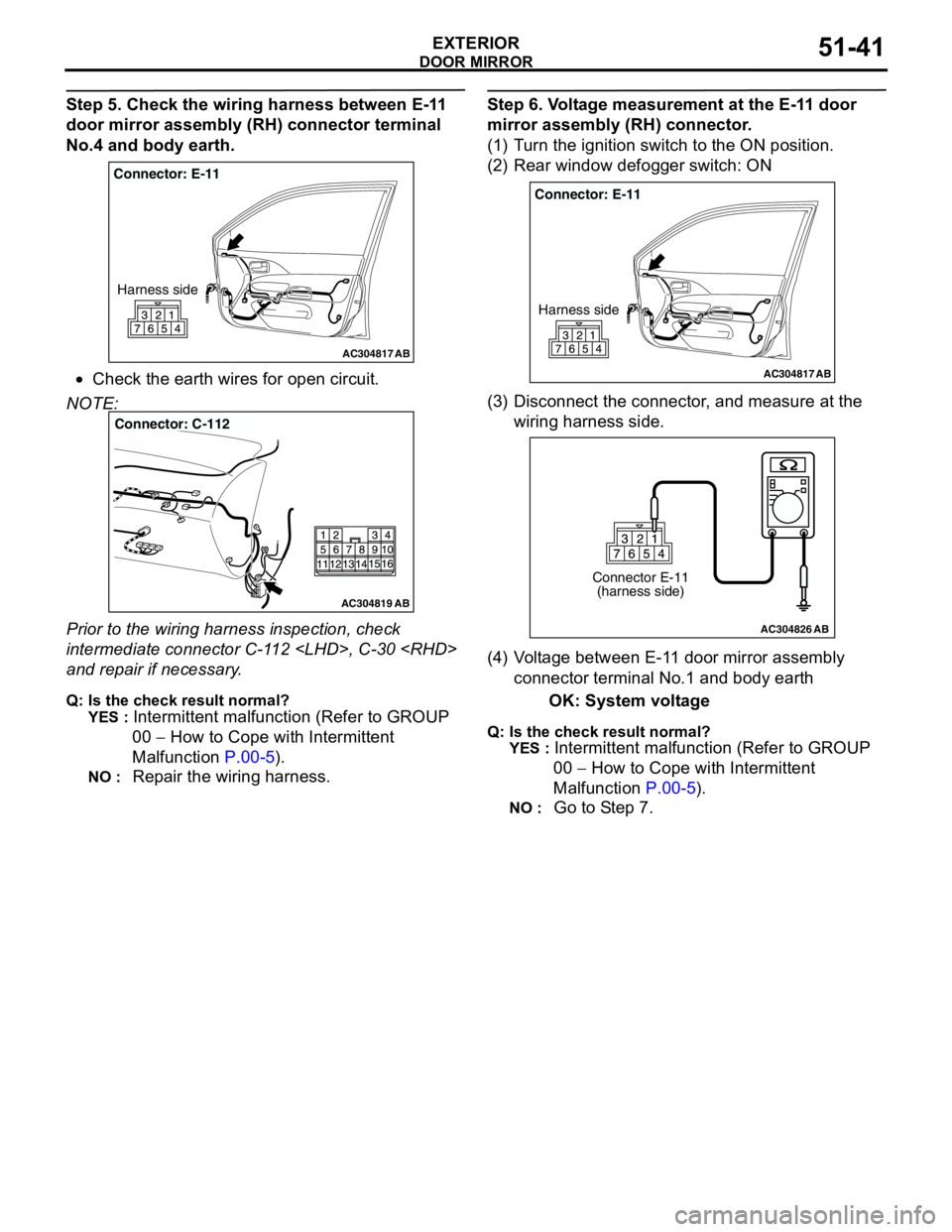
Step 5. Check the wiring harness between E-11
door mirror assembly (RH) connector terminal
No.4 and body earth.
•Check the earth wires for open circuit.
NOTE:
Prior to the wiring harness inspection, check
intermediate connector C-112
and repair if necessary.
Q: Is the check result normal?
YES :
Intermittent malfunction (Refer to GROUP
00 − How to Cope with Intermittent
Malfunction P.00-5).
NO : Repair the wiring harness.
Step 6. Voltage measurement at the E-11 door
mirror assembly (RH) connector.
(1) Turn the ignition switch to the ON position.
(2) Rear window defogger switch: ON
(3) Disconnect the connector, and measure at the
wiring harness side.
(4) Voltage between E-11 door mirror assembly
connector terminal No.1 and body earth
OK: System voltage
Q: Is the check result normal?
YES :
Intermittent malfunction (Refer to GROUP
00 − How to Cope with Intermittent
Malfunction P.00-5).
NO : Go to Step 7.
AC304817
Connector: E-11
Harness side
AB
AC304819
Connector: C-112
AB
AC304817
Connector: E-11
Harness side
AB
AC304826
Connector E-11
(harness side)
AB
Page 380 of 788
DOOR MIRROR
EXTERIOR51-42
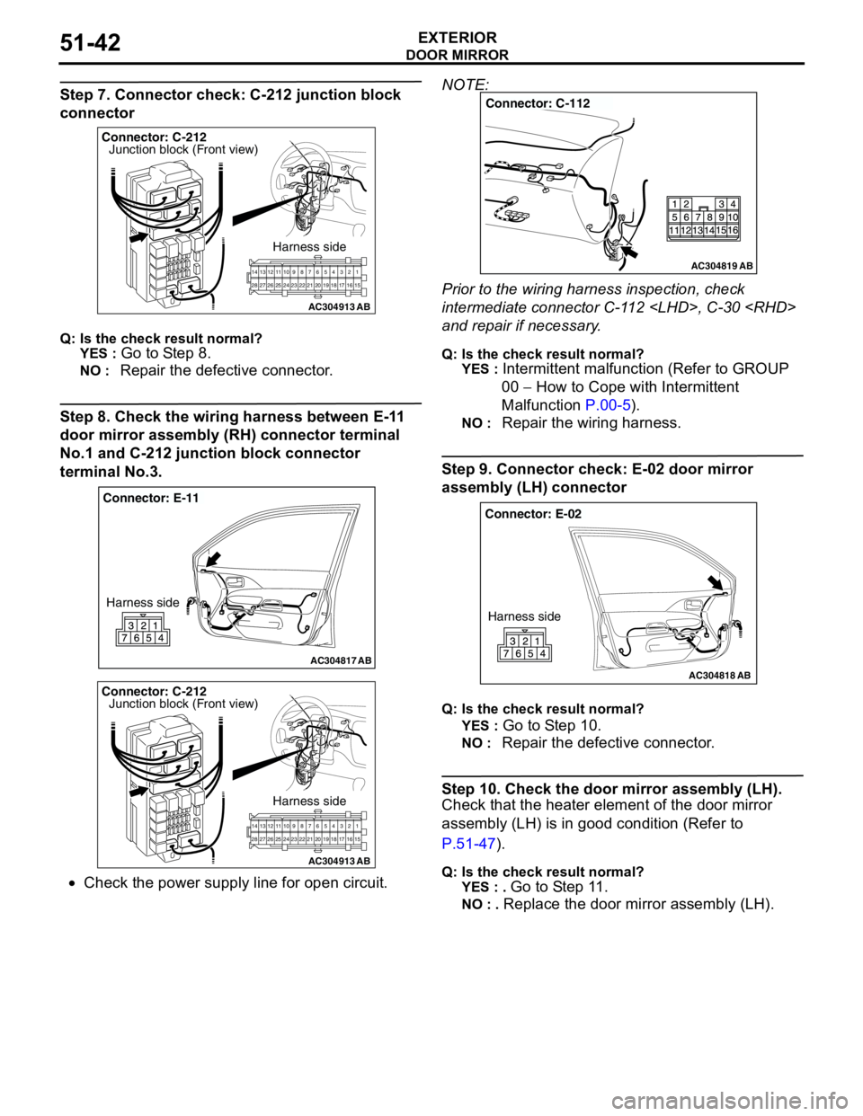
Step 7. Connector check: C-212 junction block
connector
Q: Is the check result normal?
YES :
Go to Step 8.
NO : Repair the defective connector.
Step 8. Check the wiring harness between E-11
door mirror assembly (RH) connector terminal
No.1 and C-212 junction block connector
terminal No.3.
•Check the power supply line for open circuit.NOTE:
Prior to the wiring harness inspection, check
intermediate connector C-112
and repair if necessary.
Q: Is the check result normal?
YES :
Intermittent malfunction (Refer to GROUP
00 − How to Cope with Intermittent
Malfunction P.00-5).
NO : Repair the wiring harness.
Step 9. Connector check: E-02 door mirror
assembly (LH) connector
Q: Is the check result normal?
YES :
Go to Step 10.
NO : Repair the defective connector.
Step 10. Check the door mirror assembly (LH).
Check that the heater element of the door mirror
assembly (LH) is in good condition (Refer to
P.51-47).
Q: Is the check result normal?
YES : .
Go to Step 11.
NO : . Replace the door mirror assembly (LH).
AC304913
21716151718 201912345 623 222425282627981011141213
Connector: C-212
Harness side
AB
Junction block (Front view)
AC304817
Connector: E-11
Harness side
AB
AC304913
21716151718 201912345 623 222425282627981011141213
Connector: C-212
Harness side
AB
Junction block (Front view)
AC304819
Connector: C-112
AB
AC304818
Connector: E-02
Harness side
AB
Page 381 of 788
DOOR MIRROR
EXTERIOR51-43
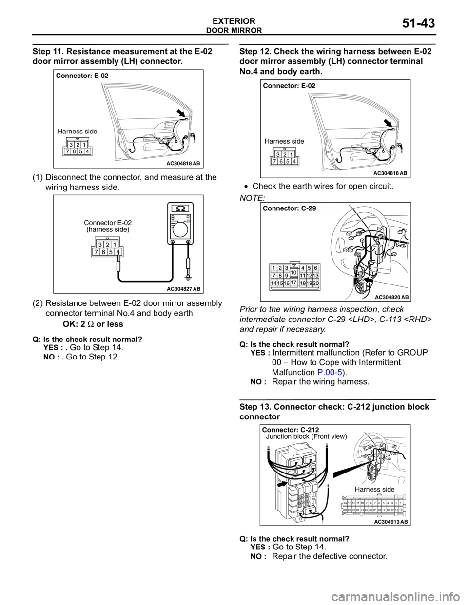
Step 11. Resistance measurement at the E-02
door mirror assembly (LH) connector.
(1) Disconnect the connector, and measure at the
wiring harness side.
(2) Resistance between E-02 door mirror assembly
connector terminal No.4 and body earth
OK: 2 Ω or less
Q: Is the check result normal?
YES : .
Go to Step 14.
NO : . Go to Step 12.
Step 12. Check the wiring harness between E-02
door mirror assembly (LH) connector terminal
No.4 and body earth.
•Check the earth wires for open circuit.
NOTE:
Prior to the wiring harness inspection, check
intermediate connector C-29
and repair if necessary.
Q: Is the check result normal?
YES :
Intermittent malfunction (Refer to GROUP
00 − How to Cope with Intermittent
Malfunction P.00-5).
NO : Repair the wiring harness.
Step 13. Connector check: C-212 junction block
connector
Q: Is the check result normal?
YES :
Go to Step 14.
NO : Repair the defective connector.
AC304818
Connector: E-02
Harness side
AB
AC304827
Connector E-02
(harness side)
AB
AC304818
Connector: E-02
Harness side
AB
AC304820
Connector: C-29
AB
AC304913
21716151718 201912345 623 222425282627981011141213
Connector: C-212
Harness side
AB
Junction block (Front view)