Group 80 MITSUBISHI LANCER 2005 Service Manual
[x] Cancel search | Manufacturer: MITSUBISHI, Model Year: 2005, Model line: LANCER, Model: MITSUBISHI LANCER 2005Pages: 788, PDF Size: 45.98 MB
Page 129 of 788

22-1
GROUP 22
MANUAL
TRANSMISSION
CONTENTS
MANUAL TRANSMISSION (FF) . . . . . . . . . . . . . . . . . . . . . . . . .22A
MANUAL TRANSMISSION OVERHAUL . . . . . . . . . . . . . . . . . .22B
Page 131 of 788
23-1
GROUP 23
AUTOMATIC
TRANSMISSION
CONTENTS
AUTOMATIC TRANSMISSION (FF) . . . . . . . . . . . . . . . . . . . . . .23A
AUTOMATIC TRANSMISSION OVERHAUL . . . . . . . . . . . . . . .23B
Page 133 of 788
26-1
GROUP 26
FRONT AXLE
CONTENTS
GENERAL INFORMATION . . . . . . . .26-2
SERVICE SPECIFICATIONS . . . . . . .26-3
LUBRICANTS . . . . . . . . . . . . . . . . . .26-3
SPECIAL TOOLS . . . . . . . . . . . . . . . .26-4
ON-VEHICLE SERVICE . . . . . . . . . . .26-7
WHEEL BEARING AXIAL PLAY CHECK . . 26-7
HUB BOLT REPLACEMENT . . . . . . . . . . . 26-7
FRONT AXLE HUB ASSEMBLY . . . .26-8
REMOVAL AND INSTALLATION . . . . . . . . 26-8
INSPECTION . . . . . . . . . . . . . . . . . . . . . . . . 26-11
DISASSEMBLY AND REASSEMBLY . . . . . 26-11
INSPECTION . . . . . . . . . . . . . . . . . . . . . . . . 26-13
DRIVE SHAFT ASSEMBLY . . . . . . . .26-14
REMOVAL AND INSTALLATION . . . . . . . . 26-14
DISASSEMBLY AND REASSEMBLY . . . . . 26-18
INSPECTION . . . . . . . . . . . . . . . . . . . . . . . . 26-21
BJ BOOT (RESIN BOOT)
REPLACEMENT . . . . . . . . . . . . . . . . . . . . . 26-21
Page 146 of 788
DRIVE SHAFT ASSEMBLY
FRONT AXLE26-14
DRIVE SHAFT ASSEMBLY
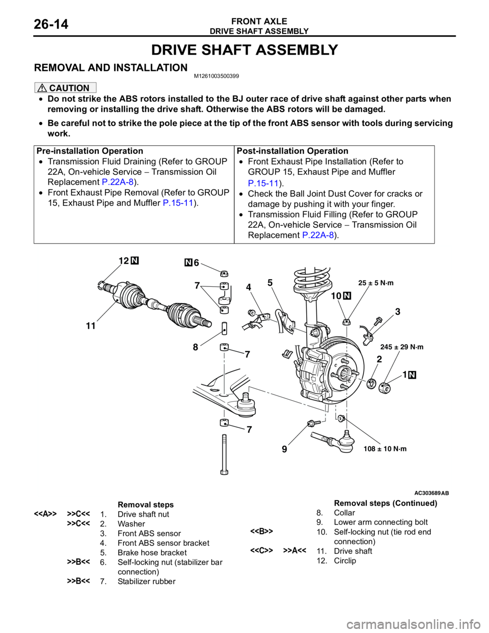
REMOVAL AND INSTALLATIONM1261003500399
CAUTION
•Do not strike the ABS rotors installed to the BJ outer race of drive shaft against other parts when
removing or installing the drive shaft. Otherwise the ABS rotors will be damaged.
•Be careful not to strike the pole piece at the tip of the front ABS sensor with tools during servicing
work.
Pre-installation Operation
•Transmission Fluid Draining (Refer to GROUP
22A, On-vehicle Service − Transmission Oil
Replacement P.22A-8).
•Front Exhaust Pipe Removal (Refer to GROUP
15, Exhaust Pipe and Muffler P.15-11).Post-installation Operation
•Front Exhaust Pipe Installation (Refer to
GROUP 15, Exhaust Pipe and Muffler
P.15-11).
•Check the Ball Joint Dust Cover for cracks or
damage by pushing it with your finger.
•Transmission Fluid Filling (Refer to GROUP
22A, On-vehicle Service − Transmission Oil
Replacement P.22A-8).
AC303689AB
9
N
N
NN
10 7
4
3
2
1
25 ± 5 N·m
245 ± 29 N·m
108 ± 10 N·m
8
5 6
1112
7
7
Removal steps
<> >>C<<1. Drive shaft nut
>>C<<2. Washer
3. Front ABS sensor
4. Front ABS sensor bracket
5. Brake hose bracket
>>B<<6. Self-locking nut (stabilizer bar
connection)
>>B<<7. Stabilizer rubber8. Collar
9. Lower arm connecting bolt
<>10. Self-locking nut (tie rod end
connection)
<
12. CirclipRemoval steps (Continued)
Page 157 of 788
27-1
GROUP 27
REAR AXLE
CONTENTS
GENERAL INFORMATION . . . . . . . .27-2
SERVICE SPECIFICATIONS . . . . . . .27-2
SEALANT . . . . . . . . . . . . . . . . . . . . . .27-2
SPECIAL TOOLS . . . . . . . . . . . . . . . .27-3ON-VEHICLE SERVICE . . . . . . . . . . .27-4
WHEEL BEARING AXIAL PLAY CHECK . . 27-4
REAR HUB ROTARY-SLIDING
RESISTANCE CHECK . . . . . . . . . . . . . . . . 27-4
HUB BOLT REPLACEMENT . . . . . . . . . . . . 27-4
REAR AXLE HUB ASSEMBLY . . . . .27-5
REMOVAL AND INSTALLATION . . . . . . . . 27-5
INSPECTION . . . . . . . . . . . . . . . . . . . . . . . . 27-6
Page 163 of 788
31-1
GROUP 31
WHEEL AND TYRE
CONTENTS
GENERAL INFORMATION . . . . . . . .31-2
SERVICE SPECIFICATIONS . . . . . . .31-2
TROUBLESHOOTING . . . . . . . . . . . .31-3
DIAGNOSIS . . . . . . . . . . . . . . . . . . . . . . . . 31-3
WHEEL BALANCE ACCURACY . . . . . . . . 31-4
ON-VEHICLE SERVICE . . . . . . . . . . .31-7
TYRE INFLATION PRESSURE CHECK . . . 31-7
TYRE WEAR CHECK . . . . . . . . . . . . . . . . . 31-7
WHEEL RUNOUT CHECK . . . . . . . . . . . . . 31-7
WHEEL AND TYRE . . . . . . . . . . . . . .31-7
INSTALLATION SERVICE POINT . . . . . . . 31-7
Page 165 of 788
TROUBLESHOOTING
WHEEL AND TYRE31-3
TROUBLESHOOTING
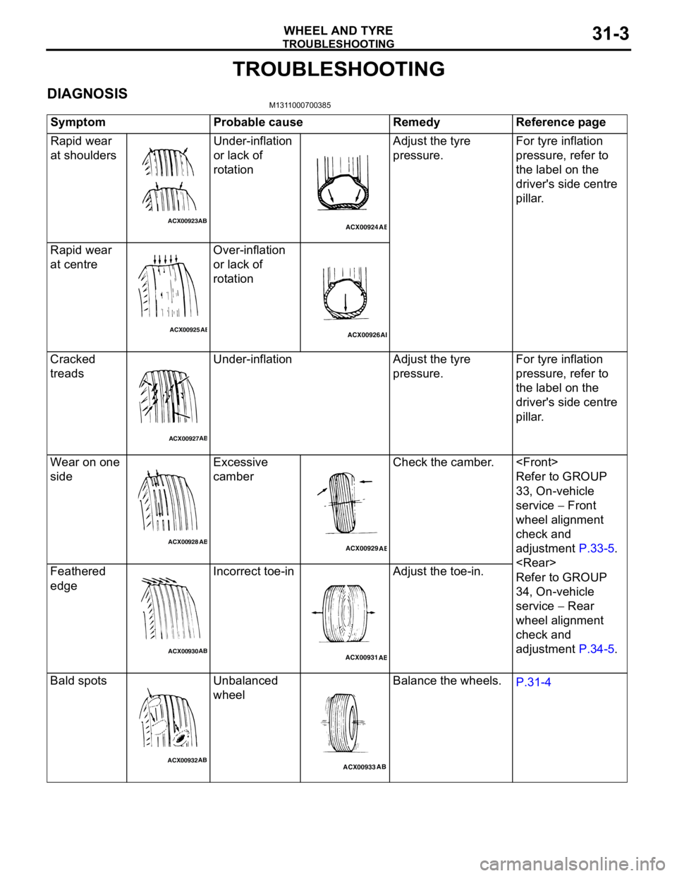
DIAGNOSISM1311000700385
Symptom Probable cause Remedy Reference page
Rapid wear
at shouldersUnder-inflation
or lack of
rotationAdjust the tyre
pressure.For tyre inflation
pressure, refer to
the label on the
driver's side centre
pillar.
Rapid wear
at centreOver-inflation
or lack of
rotation
Cracked
treadsUnder-inflation Adjust the tyre
pressure.For tyre inflation
pressure, refer to
the label on the
driver's side centre
pillar.
Wear on one
sideExcessive
camberCheck the camber.
Refer to GROUP
33, On-vehicle
service − Front
wheel alignment
check and
adjustment P.33-5.
Refer to GROUP
34, On-vehicle
service − Rear
wheel alignment
check and
adjustment P.34-5. Feathered
edgeIncorrect toe-in Adjust the toe-in.
Bald spots Unbalanced
wheelBalance the wheels.
P.31-4
ACX00923ABACX00924
AB
ACX00925ABACX00926AB
ACX00927AB
ACX00928
ABACX00929
AB
ACX00930ABACX00931
AB
ACX00932ABACX00933AB
Page 166 of 788
TROUBLESHOOTING
WHEEL AND TYRE31-4
WHEEL BALANCE ACCURACYM1311001700247
PURPOSE
This section contains tips and procedures for
achieving accurate wheel balance. Steering wheel
vibration and/or body shake can result if any of these
procedures are not carefully observed.
1. Wheels and tyres must be properly mounted on a
balancer in order to achieve correct balance.
Centring the wheel on the shaft of the balancer is
essential for proper mounting.
2. Off-the-car wheel balancers must be calibrated
periodically to ensure good balancing results. An
inaccurately calibrated balancer could cause
unnecessary replacement of tyres, shocks,
suspension components, or steering components.
Check your balancer's calibration approximately
every 100 balances. Your wheel balancer's
instruction manual should include calibration
procedures. If the calibration procedures specifically
for your balancer are missing, use the generic steps
in this section for zero calibration, static balance, and
dynamic balance checks. The wheel balancer
calibration checks are also described in the
flowchart. (Refer to P.31-6).
PROCEDURE
1. Confirm that the balancer's cone and the wheel
mounting cone are undamaged and free of dirt
and rust.
2. On this vehicle, the wheel's centre hole on the
hub side has a chamfered edge. Use a
back-mounting cone on your wheel balancer to
centre the wheel on the balancer shaft.
3. Install a wheel mounting cone. The appropriate
size cone for this vehicle is 67.0 mm.
4. Before balancing the wheel, remove any wheel
weights from both sides. Also check both sides for
any damage.
5. When installing wheel weights, hammer them at a
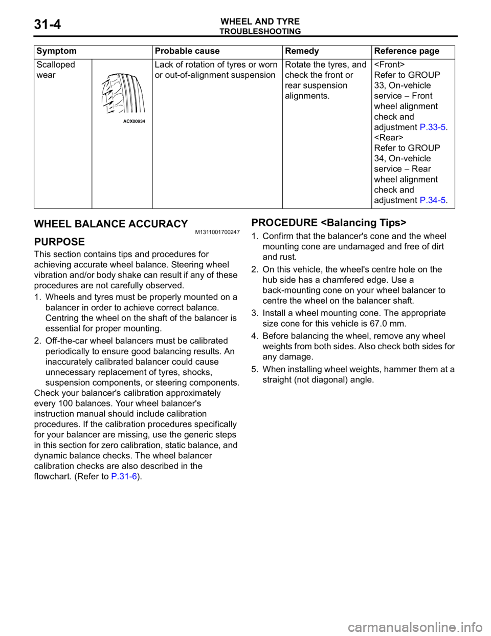
straight (not diagonal) angle. Scalloped
wearLack of rotation of tyres or worn
or out-of-alignment suspensionRotate the tyres, and
check the front or
rear suspension
alignments.
Refer to GROUP
33, On-vehicle
service − Front
wheel alignment
check and
adjustment P.33-5.
Refer to GROUP
34, On-vehicle
service − Rear
wheel alignment
check and
adjustment P.34-5. Symptom Probable cause Remedy Reference page
ACX00934
Page 171 of 788
32-1
GROUP 32
POWER PLANT
MOUNT
CONTENTS
GENERAL INFORMATION . . . . . . . .32-2
SERVICE SPECIFICATION . . . . . . . .32-3
SPECIAL TOOL . . . . . . . . . . . . . . . . .32-3
ENGINE MOUNTING . . . . . . . . . . . . .32-4
REMOVAL AND INSTALLATION . . . . . . . . 32-4
TRANSMISSION MOUNTING . . . . . .32-5
REMOVAL AND INSTALLATION . . . . . . . . 32-5
ENGINE ROLL STOPPER,
CENTERMEMBER . . . . . . . . . . . . . . .32-7
REMOVAL AND INSTALLATION . . . . . . . . 32-7
CROSSMEMBER . . . . . . . . . . . . . . . .32-8
REMOVAL AND INSTALLATION . . . . . . . . 32-8
Page 175 of 788
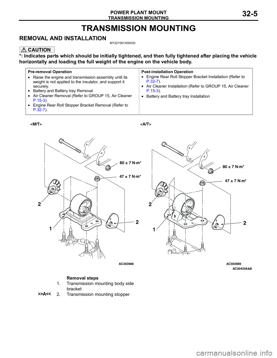
TRANSMISSION MOUNTING
POWER PLANT MOUNT32-5
TRANSMISSION MOUNTING
REMOVAL AND INSTALLATIONM1321001400430
CAUTION
*: Indicates parts which should be initially tightened, and then fully tightened after placing the vehicle
horizontally and loading the full weight of the engine on the vehicle body.
Pre-removal Operation
•Raise the engine and transmission assembly until its
weight is not applied to the insulator, and support it
securely.
•Battery and Battery tray Removal
•Air Cleaner Removal (Refer to GROUP 15, Air Cleaner
P.15-3).
•Engine Rear Roll Stopper Bracket Removal (Refer to
P.32-7).Post-installation Operation
•Engine Rear Roll Stopper Bracket Installation (Refer to
P.32-7).
•Air Cleaner Installation (Refer to GROUP 15, Air Cleaner
P.15-3).
•Battery and Battery tray Installation
AC303988AC303989
AC304258
AB
80 ± 7 N·m*
47 ± 7 N·m*80 ± 7 N·m*
47 ± 7 N·m*
1
1 2
22
2
Removal steps
1. Transmission mounting body side
bracket
>>A<<2. Transmission mounting stopper