ac compressor MITSUBISHI LANCER 2005 Repair Manual
[x] Cancel search | Manufacturer: MITSUBISHI, Model Year: 2005, Model line: LANCER, Model: MITSUBISHI LANCER 2005Pages: 788, PDF Size: 45.98 MB
Page 591 of 788
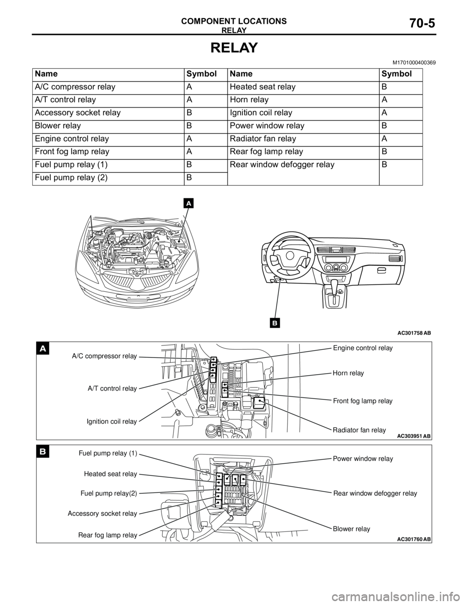
RELAY
COMPONENT LOCATIONS70-5
RELAY
M1701000400369
Name Symbol Name Symbol
A/C compressor relay A Heated seat relay B
A/T control relay A Horn relay A
Accessory socket relay B Ignition coil relay A
Blower relay B Power window relay B
Engine control relay A Radiator fan relay A
Front fog lamp relay A Rear fog lamp relay B
Fuel pump relay (1) B Rear window defogger relay B
Fuel pump relay (2) B
AC301758AB
A
B
AC303951AB
A/C compressor relayEngine control relay
Horn relay
Front fog lamp relay
Radiator fan relay A/T control relay
Ignition coil relayA
AC301760
Fuel pump relay (1)
Power window relay
Rear window defogger relay
Blower relay Heated seat relay
Fuel pump relay(2)
Accessory socket relay
Rear fog lamp relayAB
B
Page 614 of 788
ENGINE AND TRANSMISSION
CONFIGURATION DIAGRAMS80-8
ENGINE AND TRANSMISSION
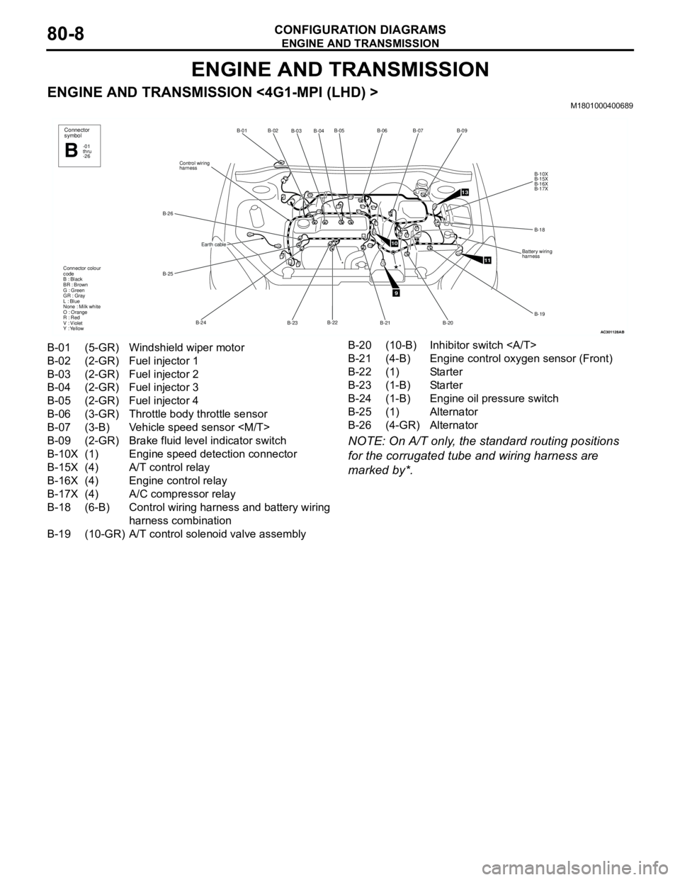
ENGINE AND TRANSMISSION <4G1-MPI (LHD) >M1801000400689
NOTE: On A/T only, the standard routing positions
for the corrugated tube and wiring harness are
marked by*.
AC301128
B-02
B-03B-04B-05
B-22
B-23 B-24 B-25 B-26Control wiring
harnessB-01
Connector colour
code
B : Black
BR : Brown
G : Green
GR : Gray
L : Blue
None : Milk white
O : Orange
R : Red
V : Violet
Y : Yellow*
Connector
symbol
-01
thru
-26B
Earth cable
AB
9
10
11
13
B-06B-07
B-09
B-10X
B-15X
B-16X
B-17X
B-18
Battery wiring
harness
B-19
B-20
B-21
*
B-01 (5-GR) Windshield wiper motor
B-02 (2-GR) Fuel injector 1
B-03 (2-GR) Fuel injector 2
B-04 (2-GR) Fuel injector 3
B-05 (2-GR) Fuel injector 4
B-06 (3-GR) Throttle body throttle sensor
B-07 (3-B) Vehicle speed sensor
B-09 (2-GR) Brake fluid level indicator switch
B-10X (1) Engine speed detection connector
B-15X (4) A/T control relay
B-16X (4) Engine control relay
B-17X (4) A/C compressor relay
B-18 (6-B) Control wiring harness and battery wiring
harness combination
B-19 (10-GR) A/T control solenoid valve assemblyB-20 (10-B) Inhibitor switch
B-21 (4-B) Engine control oxygen sensor (Front)
B-22 (1) Starter
B-23 (1-B) Starter
B-24 (1-B) Engine oil pressure switch
B-25 (1) Alternator
B-26 (4-GR) Alternator
Page 615 of 788
ENGINE AND TRANSMISSION
CONFIGURATION DIAGRAMS80-9
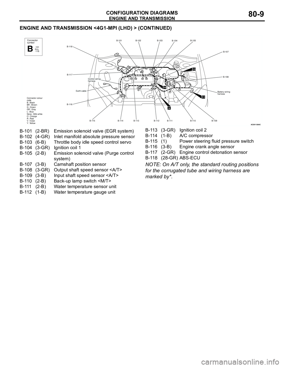
ENGINE AND TRANSMISSION <4G1-MPI (LHD) > (CONTINUED)
NOTE: On A/T only, the standard routing positions
for the corrugated tube and wiring harness are
marked by*.
AC301128
B-118B-101 B-102
B-113
B-114 B-115 B-116B-117
Earth cable
Control wiring
harness
Connector colour
code
B : Black
BR : Brown
G : Green
GR : Gray
L : Blue
None : Milk white
O : Orange
R : Red
V : Violet
Y : Yellow
Connector
symbol
-101
thru
-118B
*
AC
9
10
11
13
B-103
B-104B-105
B-107
B-108
Battery wiring
harness
B-109
B-110 B-111
*
B-112
B-101 (2-BR) Emission solenoid valve (EGR system)
B-102 (4-GR) Inlet manifold absolute pressure sensor
B-103 (6-B) Throttle body idle speed control servo
B-104 (3-GR) Ignition coil 1
B-105 (2-B) Emission solenoid valve (Purge control
system)
B-107 (3-B) Camshaft position sensor
B-108 (3-GR) Output shaft speed sensor
B-109 (3-B) Input shaft speed sensor
B-110 (2-B) Back-up lamp switch
B-111 (2-B) Water temperature sensor unit
B-112 (1-B) Water temperature gauge unitB-113 (3-GR) Ignition coil 2
B-114 (1-B) A/C compressor
B-115 (1) Power steering fluid pressure switch
B-116 (3-B) Engine crank angle sensor
B-117 (2-GR) Engine control detonation sensor
B-118 (28-GR) ABS-ECU
Page 616 of 788
ENGINE AND TRANSMISSION
CONFIGURATION DIAGRAMS80-10
ENGINE AND TRANSMISSION
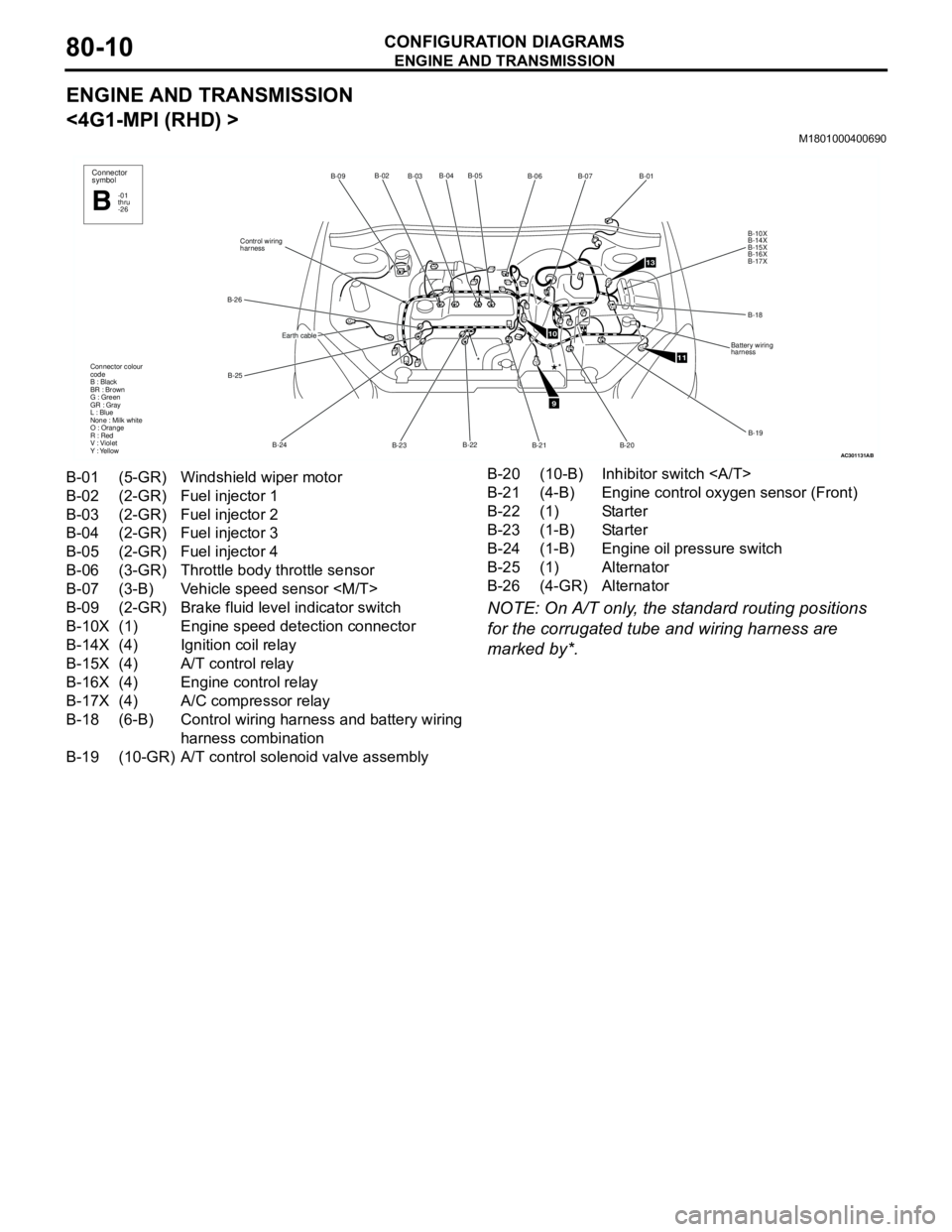
<4G1-MPI (RHD) >
M1801000400690
NOTE: On A/T only, the standard routing positions
for the corrugated tube and wiring harness are
marked by*.
AC301131
B-02
B-03B-04 B-05
B-22
B-23 B-24 B-25 B-26Control wiring
harnessB-09
Connector colour
code
B : Black
BR : Brown
G : Green
GR : Gray
L : Blue
None : Milk white
O : Orange
R : Red
V : Violet
Y : Yellow*
Connector
symbol
-01
thru
-26B
Earth cable
AB
9
10
11
13
B-06B-07
B-01
B-10X
B-14X
B-15X
B-16X
B-17X
B-18
Battery wiring
harness
B-19
B-20 B-21
*
B-01 (5-GR) Windshield wiper motor
B-02 (2-GR) Fuel injector 1
B-03 (2-GR) Fuel injector 2
B-04 (2-GR) Fuel injector 3
B-05 (2-GR) Fuel injector 4
B-06 (3-GR) Throttle body throttle sensor
B-07 (3-B) Vehicle speed sensor
B-09 (2-GR) Brake fluid level indicator switch
B-10X (1) Engine speed detection connector
B-14X (4) Ignition coil relay
B-15X (4) A/T control relay
B-16X (4) Engine control relay
B-17X (4) A/C compressor relay
B-18 (6-B) Control wiring harness and battery wiring
harness combination
B-19 (10-GR) A/T control solenoid valve assemblyB-20 (10-B) Inhibitor switch
B-21 (4-B) Engine control oxygen sensor (Front)
B-22 (1) Starter
B-23 (1-B) Starter
B-24 (1-B) Engine oil pressure switch
B-25 (1) Alternator
B-26 (4-GR) Alternator
Page 617 of 788

ENGINE AND TRANSMISSION
CONFIGURATION DIAGRAMS80-11
ENGINE AND TRANSMISSION <4G1-MPI (RHD) > (CONTINUED)
NOTE: On A/T only, the standard routing positions
for the corrugated tube and wiring harness are
marked by*.
AC301131
B-117B-101 B-102
B-113 B-114 B-115 B-116
Earth cable
Control wiring
harness
Connector colour
code
B : Black
BR : Brown
G : Green
GR : Gray
L : Blue
None : Milk white
O : Orange
R : Red
V : Violet
Y : Yellow
Connector
symbol
-101
thru
-118B
*
AC
9
10
11
13
B-103
B-104B-105
B-107
B-108
Battery wiring
harness
B-109 B-110 B-111
*
B-112
B-118
B-101 (2-BR) Emission solenoid valve (EGR system)
B-102 (4-GR) Inlet manifold absolute pressure sensor
B-103 (6-B) Throttle body idle speed control servo
B-104 (3-GR) Ignition coil 1
B-105 (2-B) Emission solenoid valve (Purge control
system)
B-107 (3-B) Camshaft position sensor
B-108 (3-GR) Output shaft speed sensor
B-109 (3-B) Input shaft speed sensor
B-110 (2-B) Back-up lamp switch
B-111 (2-B) Water temperature sensor unit
B-112 (1-B) Water temperature gauge unitB-113 (3-GR) Ignition coil 2
B-114 (1-B) A/C compressor
B-115 (1) Power steering fluid pressure switch
B-116 (3-B) Engine crank angle sensor
B-117 (2-GR) Engine control detonation sensor
B-118 (28-GR) ABS-ECU
Page 618 of 788
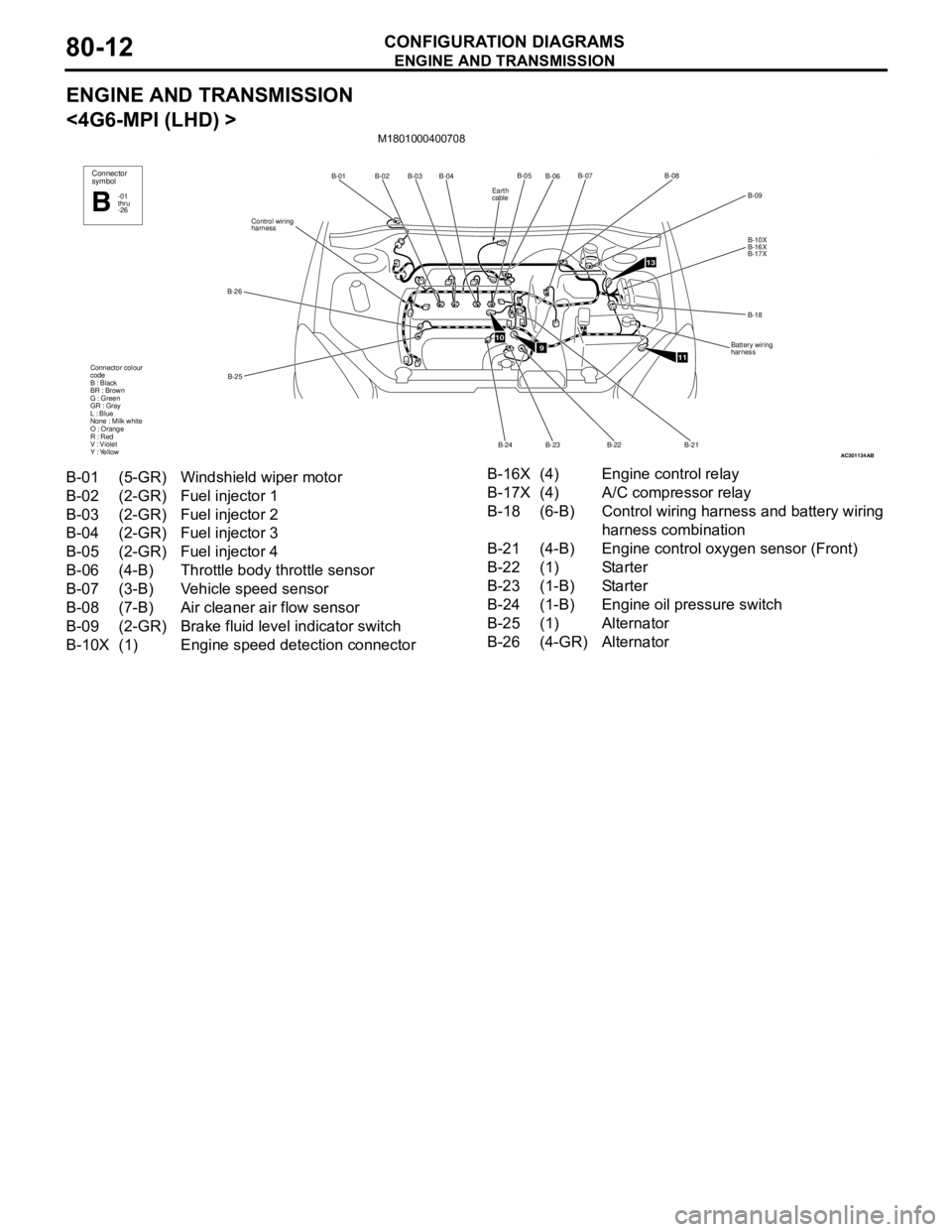
ENGINE AND TRANSMISSION
CONFIGURATION DIAGRAMS80-12
ENGINE AND TRANSMISSION
<4G6-MPI (LHD) >
M1801000400708
AC301134
B-02
B-03B-04
B-25 B-26Control wiring
harnessB-01
Connector colour
code
B : Black
BR : Brown
G : Green
GR : Gray
L : Blue
None : Milk white
O : Orange
R : Red
V : Violet
Y : YellowConnector
symbol
-01
thru
-26B
AB
910
11
13
B-06B-07
B-09
B-10X
B-16X
B-17X
B-18
Battery wiring
harness
B-21 B-22
B-23B-05B-08
B-24
Earth
cable
B-01 (5-GR) Windshield wiper motor
B-02 (2-GR) Fuel injector 1
B-03 (2-GR) Fuel injector 2
B-04 (2-GR) Fuel injector 3
B-05 (2-GR) Fuel injector 4
B-06 (4-B) Throttle body throttle sensor
B-07 (3-B) Vehicle speed sensor
B-08 (7-B) Air cleaner air flow sensor
B-09 (2-GR) Brake fluid level indicator switch
B-10X (1) Engine speed detection connectorB-16X (4) Engine control relay
B-17X (4) A/C compressor relay
B-18 (6-B) Control wiring harness and battery wiring
harness combination
B-21 (4-B) Engine control oxygen sensor (Front)
B-22 (1) Starter
B-23 (1-B) Starter
B-24 (1-B) Engine oil pressure switch
B-25 (1) Alternator
B-26 (4-GR) Alternator
Page 619 of 788
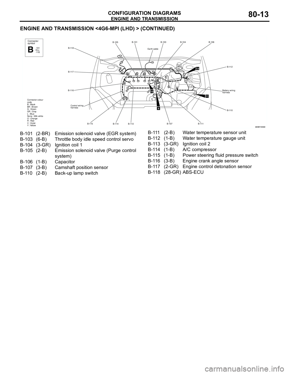
ENGINE AND TRANSMISSION
CONFIGURATION DIAGRAMS80-13
ENGINE AND TRANSMISSION <4G6-MPI (LHD) > (CONTINUED)
AC301134
B-118B-101
B-114 B-115 B-116B-117
Control wiring
harness Connector colour
code
B : Black
BR : Brown
G : Green
GR : Gray
L : Blue
None : Milk white
O : Orange
R : Red
V : Violet
Y : Yellow
B-113
B-105Connector
symbol
-101
thru
-118B
AC
9
10
11
13
B-103B-104B-106
B-112
B-110 Battery wiring
harness
B-111
B-107
Earth cable
B-101 (2-BR) Emission solenoid valve (EGR system)
B-103 (6-B) Throttle body idle speed control servo
B-104 (3-GR) Ignition coil 1
B-105 (2-B) Emission solenoid valve (Purge control
system)
B-106 (1-B) Capacitor
B-107 (3-B) Camshaft position sensor
B-110 (2-B) Back-up lamp switch B-111 (2-B) Water temperature sensor unit
B-112 (1-B) Water temperature gauge unit
B-113 (3-GR) Ignition coil 2
B-114 (1-B) A/C compressor
B-115 (1-B) Power steering fluid pressure switch
B-116 (3-B) Engine crank angle sensor
B-117 (2-GR) Engine control detonation sensor
B-118 (28-GR) ABS-ECU
Page 620 of 788
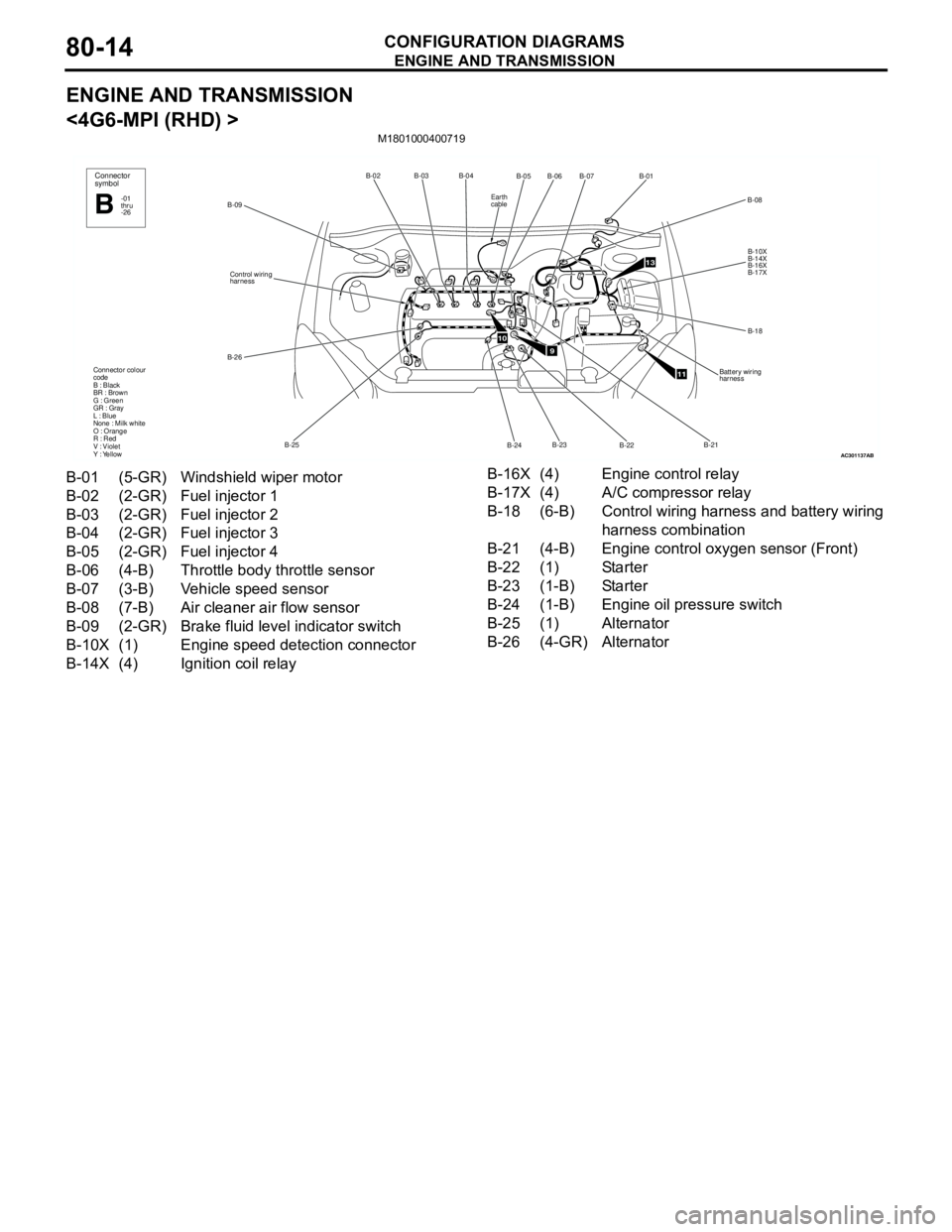
ENGINE AND TRANSMISSION
CONFIGURATION DIAGRAMS80-14
ENGINE AND TRANSMISSION
<4G6-MPI (RHD) >
M1801000400719
AC301137
B-02B-03B-04
B-25 B-26Control wiring
harness
B-09
Connector colour
code
B : Black
BR : Brown
G : Green
GR : Gray
L : Blue
None : Milk white
O : Orange
R : Red
V : Violet
Y : Yellow
Connector
symbol
-01
thru
-26B
AB
910
11
13
B-05
B-07B-01
B-10X
B-14X
B-16X
B-17X
B-18
Battery wiring
harness
B-22 B-24B-06
B-08
B-23B-21
Earth
cable
B-01 (5-GR) Windshield wiper motor
B-02 (2-GR) Fuel injector 1
B-03 (2-GR) Fuel injector 2
B-04 (2-GR) Fuel injector 3
B-05 (2-GR) Fuel injector 4
B-06 (4-B) Throttle body throttle sensor
B-07 (3-B) Vehicle speed sensor
B-08 (7-B) Air cleaner air flow sensor
B-09 (2-GR) Brake fluid level indicator switch
B-10X (1) Engine speed detection connector
B-14X (4) Ignition coil relayB-16X (4) Engine control relay
B-17X (4) A/C compressor relay
B-18 (6-B) Control wiring harness and battery wiring
harness combination
B-21 (4-B) Engine control oxygen sensor (Front)
B-22 (1) Starter
B-23 (1-B) Starter
B-24 (1-B) Engine oil pressure switch
B-25 (1) Alternator
B-26 (4-GR) Alternator
Page 621 of 788
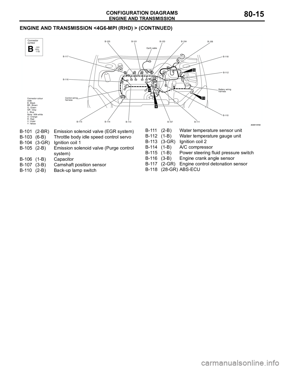
ENGINE AND TRANSMISSION
CONFIGURATION DIAGRAMS80-15
ENGINE AND TRANSMISSION <4G6-MPI (RHD) > (CONTINUED)
AC301137
B-117B-105 B-101
B-113 B-114 B-115 B-116
Control wiring
harness Connector colour
code
B : Black
BR : Brown
G : Green
GR : Gray
L : Blue
None : Milk white
O : Orange
R : Red
V : Violet
Y : Yellow
Connector
symbol
-101
thru
-118B
AC
9
11
13
B-103
B-106
B-118
B-112
Battery wiring
harness
B-110
B-111
B-107
B-104
10
Earth cable
B-101 (2-BR) Emission solenoid valve (EGR system)
B-103 (6-B) Throttle body idle speed control servo
B-104 (3-GR) Ignition coil 1
B-105 (2-B) Emission solenoid valve (Purge control
system)
B-106 (1-B) Capacitor
B-107 (3-B) Camshaft position sensor
B-110 (2-B) Back-up lamp switch B-111 (2-B) Water temperature sensor unit
B-112 (1-B) Water temperature gauge unit
B-113 (3-GR) Ignition coil 2
B-114 (1-B) A/C compressor
B-115 (1-B) Power steering fluid pressure switch
B-116 (3-B) Engine crank angle sensor
B-117 (2-GR) Engine control detonation sensor
B-118 (28-GR) ABS-ECU
Page 648 of 788

CENTRALIZED JUNCTION
CIRCUIT DIAGRAMS90-10
CENTRALIZED JUNCTION
M1901000300991
FUSIBLE LINK AND FUSE
ENGINE COMPARTMENT
No. Power supply circuit Name Rated
capacity (A)Housing
colourLoad circuit
1 Battery/ Alternator
(Fusible link No.26)Fusible
link60 Yellow Fuse No.15, 16, 19, 20 (in junction
block) circuit
2 50 Red Fan controller
3 60 Yellow ABS-ECU
4 40 Green Ignition switch circuit
5 30 Pink Power window main switch and power
window sub switch
6 Fuse 15 Blue Front fog lamp, front fog lamp
indicator lamp, front fog lamp relay
and spare connector (for front fog
lamp)
7 10 Red Horn relay and horn
8 20 Yellow Air cleaner air flow sensor, camshaft
position sensor, emission solenoid
valve (EGR system), emission
solenoid valve (purge control system),
engine-A/T-ECU, engine-ECU, engine
control oxygen sensor, engine control
relay, engine crank angle sensor, fan
control relay, fuel injector, ignition coil
relay, immobilizer-ECU and throttle
body idle speed control servo
9 10 Red A/C compressor
10 15 Blue ABS-ECU, engine-A/T-ECU, high
mount stop lamp and rear combination
lamp
11 15 Blue Accessory socket
12 7.5 Brown Alternator
13 10 Red ETACS-ECU, front turn signal lamp,
rear combination lamp, side turn
signal lamp and turn signal indicator
lamp
14 20 Yellow A/T control solenoid valve assembly
and engine-A/T-ECU
15 15 Blue Fuel pump
16 Front-ECU
(Headlamp relay: HI)10 Red Headlamp (RH)
17 10 Red Headlamp (LH) and high beam
indicator lamp
18 Front-ECU
(Headlamp relay: LO)10 Red Headlamp (RH)
19 10 Red Headlamp (LH), headlamp assembly
and headlamp levelling switch