ac compressor MITSUBISHI LANCER 2005 User Guide
[x] Cancel search | Manufacturer: MITSUBISHI, Model Year: 2005, Model line: LANCER, Model: MITSUBISHI LANCER 2005Pages: 788, PDF Size: 45.98 MB
Page 487 of 788

SERVICE SPECIFICATIONS
HEATER, AIR CONDITIONER AND VENTILATION55-3
SERVICE SPECIFICATIONS
M1552000300292
LUBRICANTS
M1552000400299
ItemStandard value
Idle speed r/min 750 ± 100
Idle-up speed r/min 850 ± 100
Resistor (for blower motor) ΩLO 2.54
ML 1.24
MH 0.6
Air gap (magnetic clutch) mm 0.3 − 0.5
Item Specified lubricant Quantity
Compressor refrigerant unit lubricant SUN PAG 56 1300, 1600 140 mL
2000 120 mL
Each connection of refrigerant line SUN PAG 56 As required
Refrigerant R134a (HFC-134a) 480 − 520 g
Page 488 of 788
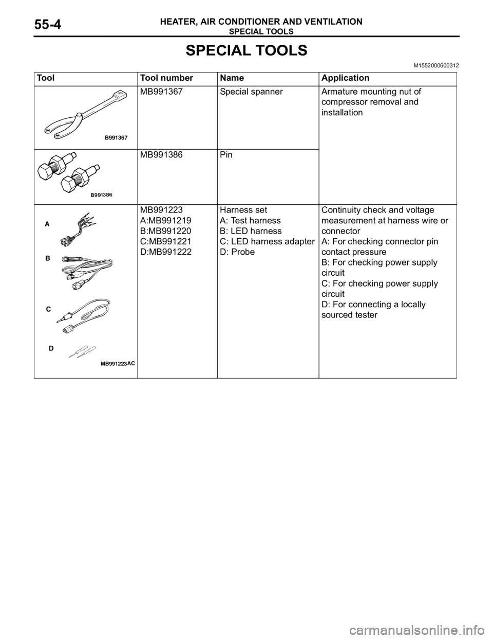
SPECIAL TOOLS
HEATER, AIR CONDITIONER AND VENTILATION55-4
SPECIAL TOOLS
M1552000600312
Tool Tool number Name Application
MB991367 Special spanner Armature mounting nut of
compressor removal and
installation
MB991386 Pin
MB991223
A:MB991219
B:MB991220
C:MB991221
D:MB991222Harness set
A: Test harness
B: LED harness
C: LED harness adapter
D: ProbeContinuity check and voltage
measurement at harness wire or
connector
A: For checking connector pin
contact pressure
B: For checking power supply
circuit
C: For checking power supply
circuit
D: For connecting a locally
sourced tester
B991367
MB991223
A
B
C
D
AC
Page 489 of 788
TROUBLESHOOTING
HEATER, AIR CONDITIONER AND VENTILATION55-5
TROUBLESHOOTING
DIAGNOSIS TROUBLESHOOTING FLOWM1552009600364
Refer to GROUP 00, How to Use
Troubleshooting/Inspection Service Points P.00-5.
SYMPTOM CHARTM1552009900611
NOTE: Refer to GROUP 14, Troubleshooting P.14-5
for the condenser fan.
SYMPTOM PROCEDURES
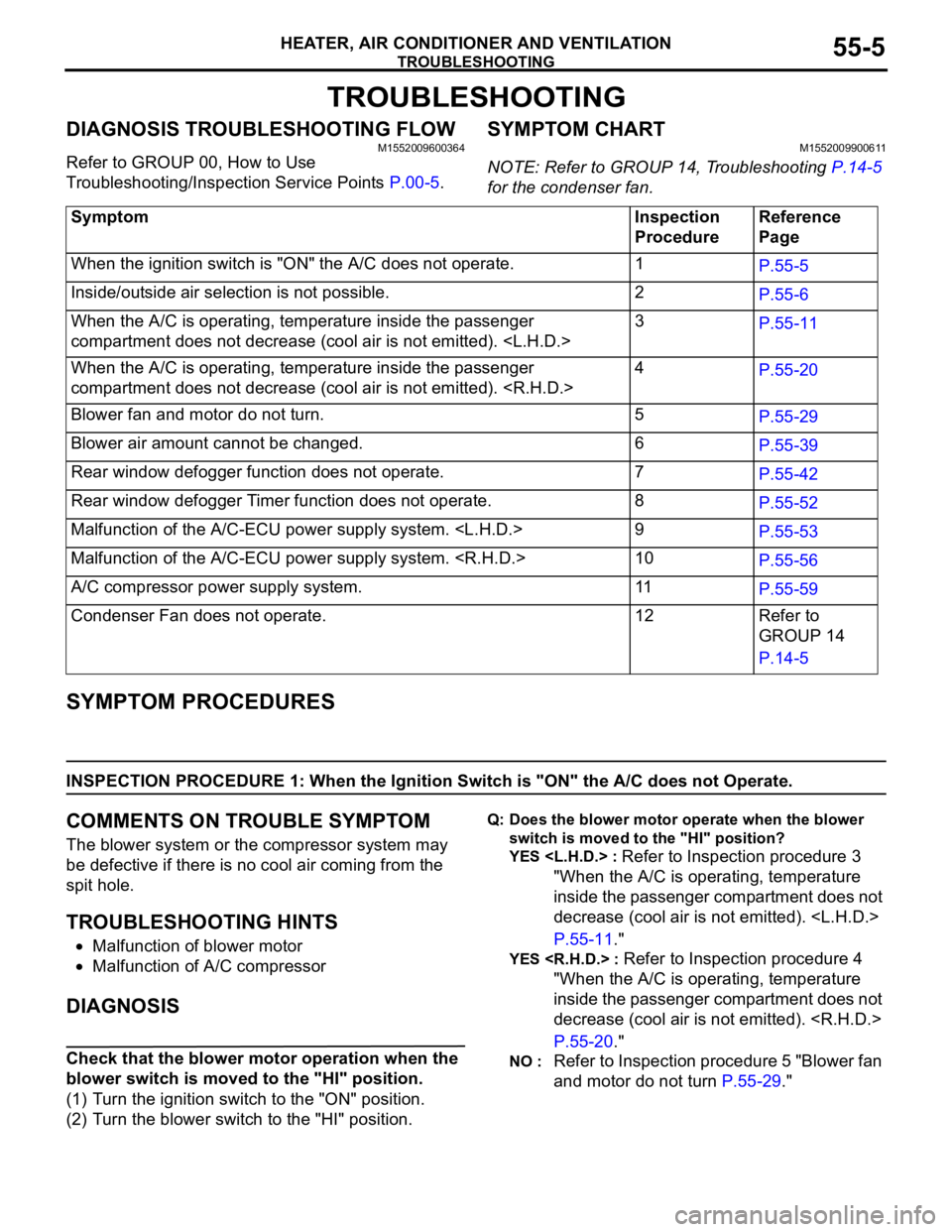
INSPECTION PROCEDURE 1: When the Ignition Switch is "ON" the A/C does not Operate.
COMMENTS ON TROUBLE SYMPTOM
The blower system or the compressor system may
be defective if there is no cool air coming from the
spit hole.
TROUBLESHOOTING HINTS
•Malfunction of blower motor
•Malfunction of A/C compressor
DIAGNOSIS
Check that the blower motor operation when the
blower switch is moved to the "HI" position.
(1) Turn the ignition switch to the "ON" position.
(2) Turn the blower switch to the "HI" position.
Q: Does the blower motor operate when the blower
switch is moved to the "HI" position?
YES
Refer to Inspection procedure 3
"When the A/C is operating, temperature
inside the passenger compartment does not
decrease (cool air is not emitted).
P.55-11."
YES
"When the A/C is operating, temperature
inside the passenger compartment does not
decrease (cool air is not emitted).
P.55-20."
NO : Refer to Inspection procedure 5 "Blower fan
and motor do not turn P.55-29." Symptom Inspection
ProcedureReference
Page
When the ignition switch is "ON" the A/C does not operate. 1
P.55-5
Inside/outside air selection is not possible. 2
P.55-6
When the A/C is operating, temperature inside the passenger
compartment does not decrease (cool air is not emitted).
P.55-11
When the A/C is operating, temperature inside the passenger
compartment does not decrease (cool air is not emitted).
P.55-20
Blower fan and motor do not turn. 5
P.55-29
Blower air amount cannot be changed. 6
P.55-39
Rear window defogger function does not operate. 7
P.55-42
Rear window defogger Timer function does not operate. 8
P.55-52
Malfunction of the A/C-ECU power supply system.
P.55-53
Malfunction of the A/C-ECU power supply system.
P.55-56
A/C compressor power supply system. 11
P.55-59
Condenser Fan does not operate. 12 Refer to
GROUP 14
P.14-5
Page 496 of 788
TROUBLESHOOTING
HEATER, AIR CONDITIONER AND VENTILATION55-12
COMMENTS ON TROUBLE SYMPTOM
If cool air is not distributed when the A/C switch is on,
the air thermo sensor or the A/C compressor relay
system may be defective.
TROUBLESHOOTING HINTS
•Improper amount of refrigerant
•Malfunction of the air thermo sensor
•Malfunction of the dual pressure switch
•Malfunction of the A/C compressor relay
•Malfunction of the A/C refrigerant temperature
switch
•Malfunction of the magnetic clutch
•Malfunction of the manual air conditioner control
panel (A/C-ECU)
•Damaged the wiring harness or connectors
•Malfunction of the engine-ECU
engine-A/T-ECU
DIAGNOSIS
STEP 1. Check the defogger and outside/inside
air selection damper control motor operation.
Q: Do the defogger and outside/inside air selection
damper control motor work normally?
YES :
Go to Step 2.
NO : Refer to Inspection procedure 9
"Malfunction of the A/C-ECU power supply
system
STEP 2. Check the blower motor operation.
Q: Does the blower motor work normally?
YES :
Go to Step 3.
NO : Refer to Inspection procedure 5 "Blower fan
and motor do not turn P.55-29."
STEP 3. Check the A/C compressor.
Check the A/C compressor for compressor oil leaks.
Q: Is the check result satisfactory?
YES :
Go to Step 4.
NO : Replace the A/C compressor or the
expansion valve.
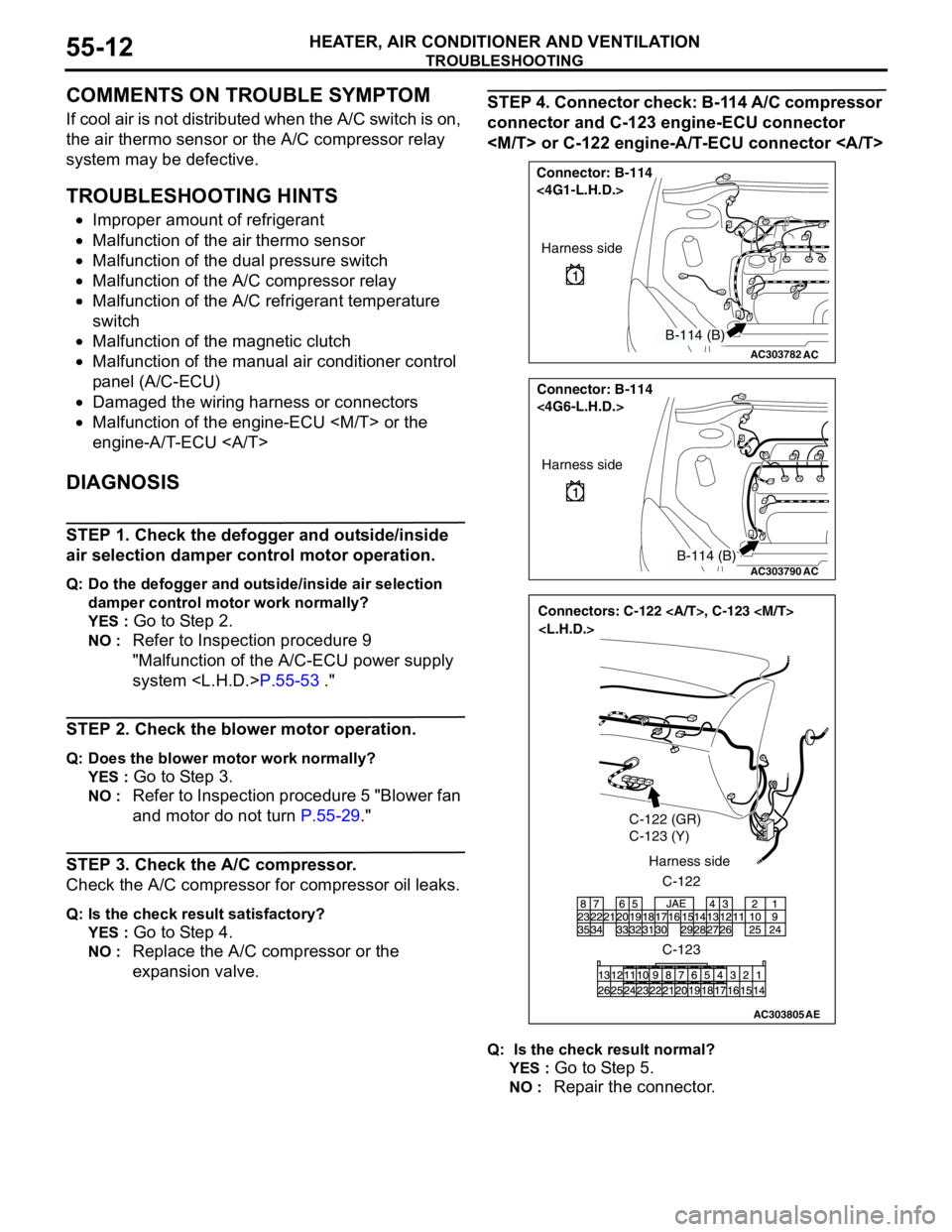
STEP 4. Connector check: B-114 A/C compressor
connector and C-123 engine-ECU connector
Q: Is the check result normal?
YES :
Go to Step 5.
NO : Repair the connector.
AC303782
Connector: B-114
<4G1-L.H.D.>
AC
Harness side
B-114 (B)
AC303790
Connector: B-114
<4G6-L.H.D.>
AC
Harness side
B-114 (B)
AC303805
Connectors: C-122 , C-123
C-122 (GR)
C-123 (Y)
C-122 Harness side
C-123
AE
Page 497 of 788
TROUBLESHOOTING
HEATER, AIR CONDITIONER AND VENTILATION55-13
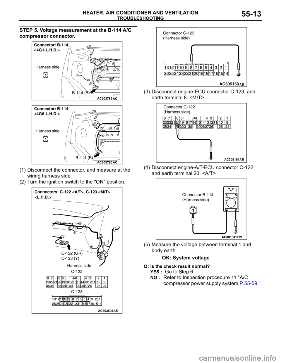
STEP 5. Voltage measurement at the B-114 A/C
compressor connector.
(1) Disconnect the connector, and measure at the
wiring harness side.
(2) Turn the ignition switch to the "ON" position.(3) Disconnect engine-ECU connector C-123, and
earth terminal 8.
(4) Disconnect engine-A/T-ECU connector C-122,
and earth terminal 20.
(5) Measure the voltage between terminal 1 and
body earth.
OK: System voltage
Q: Is the check result normal?
YES :
Go to Step 6.
NO : Refer to Inspection procedure 11 "A/C
compressor power supply system P.55-59."
AC303782
Connector: B-114
<4G1-L.H.D.>
AC
Harness side
B-114 (B)
AC303790
Connector: B-114
<4G6-L.H.D.>
AC
Harness side
B-114 (B)
AC303805
Connectors: C-122 , C-123
C-122 (GR)
C-123 (Y)
C-122 Harness side
C-123
AE
AC305159 Connector C-123
(Harness side)AB
AC305161
Connector C-122
(Harness side)
AB
AC301541EW
Connector B-114
(Harness side)
1
Page 503 of 788
TROUBLESHOOTING
HEATER, AIR CONDITIONER AND VENTILATION55-19
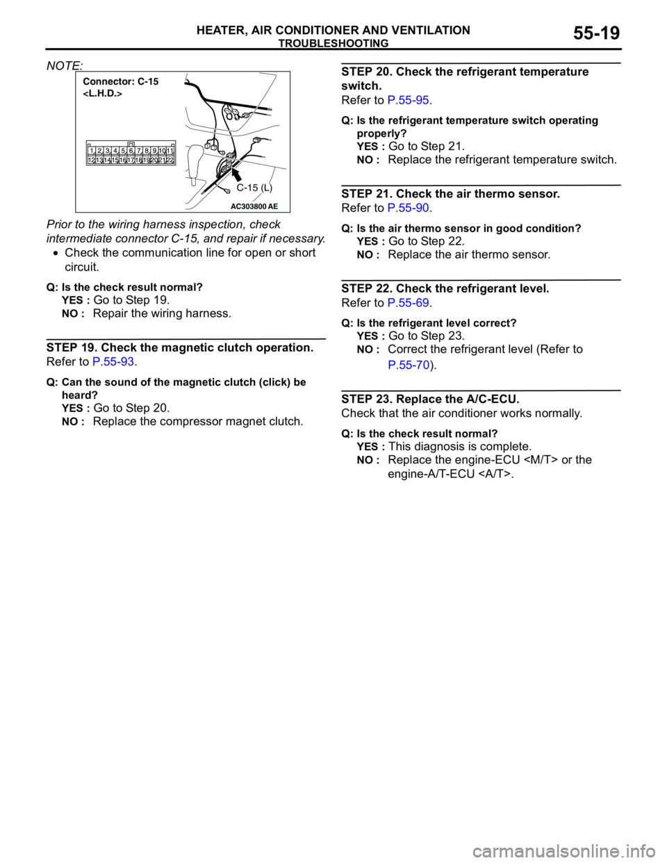
NOTE:
Prior to the wiring harness inspection, check
intermediate connector C-15, and repair if necessary.
•Check the communication line for open or short
circuit.
Q: Is the check result normal?
YES :
Go to Step 19.
NO : Repair the wiring harness.
STEP 19. Check the magnetic clutch operation.
Refer to P.55-93.
Q: Can the sound of the magnetic clutch (click) be
heard?
YES :
Go to Step 20.
NO : Replace the compressor magnet clutch.
STEP 20. Check the refrigerant temperature
switch.
Refer to P.55-95.
Q: Is the refrigerant temperature switch operating
properly?
YES :
Go to Step 21.
NO : Replace the refrigerant temperature switch.
STEP 21. Check the air thermo sensor.
Refer to P.55-90.
Q: Is the air thermo sensor in good condition?
YES :
Go to Step 22.
NO : Replace the air thermo sensor.
STEP 22. Check the refrigerant level.
Refer to P.55-69.
Q: Is the refrigerant level correct?
YES :
Go to Step 23.
NO : Correct the refrigerant level (Refer to
P.55-70).
STEP 23. Replace the A/C-ECU.
Check that the air conditioner works normally.
Q: Is the check result normal?
YES :
This diagnosis is complete.
NO : Replace the engine-ECU
engine-A/T-ECU .
AC303800
Connector: C-15
AE
C-15 (L)
Page 505 of 788
TROUBLESHOOTING
HEATER, AIR CONDITIONER AND VENTILATION55-21
COMMENTS ON TROUBLE SYMPTOM
If cool air is not distributed when the A/C switch is on,
the air thermo sensor or the A/C compressor relay
system may be defective.
TROUBLESHOOTING HINTS
•Improper amount of refrigerant
•Malfunction of the air thermo sensor
•Malfunction of the dual pressure switch
•Malfunction of the A/C compressor relay
•Malfunction of the A/C refrigerant temperature
switch
•Malfunction of the magnetic clutch
•Malfunction of the manual air conditioner control
panel (A/C-ECU)
•Damaged the wiring harness or connectors
•Malfunction of the engine-ECU
engine-A/T-ECU
DIAGNOSIS
STEP 1. Check the defogger and outside/inside
air selection damper control motor operation.
Q: Do the defogger and outside/inside air selection
damper control motor work normally?
YES :
Go to Step 2.
NO : Refer to Inspection procedure 10
"Malfunction of the A/C-ECU power supply
system
STEP 2. Check the blower motor operation.
Q: Does the blower motor work normally?
YES :
Go to Step 3.
NO : Refer to Inspection procedure 5 "Blower fan
and motor do not turn P.55-29."
STEP 3. Check the A/C compressor.
Check the A/C compressor for compressor oil leaks.
Q: Is the check result satisfactory?
YES :
Go to Step 4.
NO : Replace the A/C compressor or the
expansion valve.
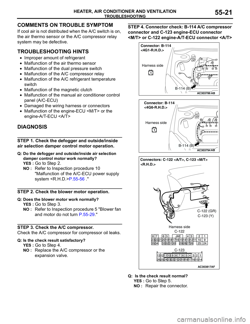
STEP 4. Connector check: B-114 A/C compressor
connector and C-123 engine-ECU connector
Q: Is the check result normal?
YES :
Go to Step 5.
NO : Repair the connector.
AC303786
Connector: B-114
<4G1-R.H.D.>
AB
Harness side
B-114 (B)
AC303794
Connector: B-114
<4G6-R.H.D.>
AB
Harness side
B-114 (B)
AC303817
Connectors: C-122 , C-123
AF
C-122C-122 (GR)
C-123 (Y)
C-123 Harness side
Page 506 of 788
TROUBLESHOOTING
HEATER, AIR CONDITIONER AND VENTILATION55-22
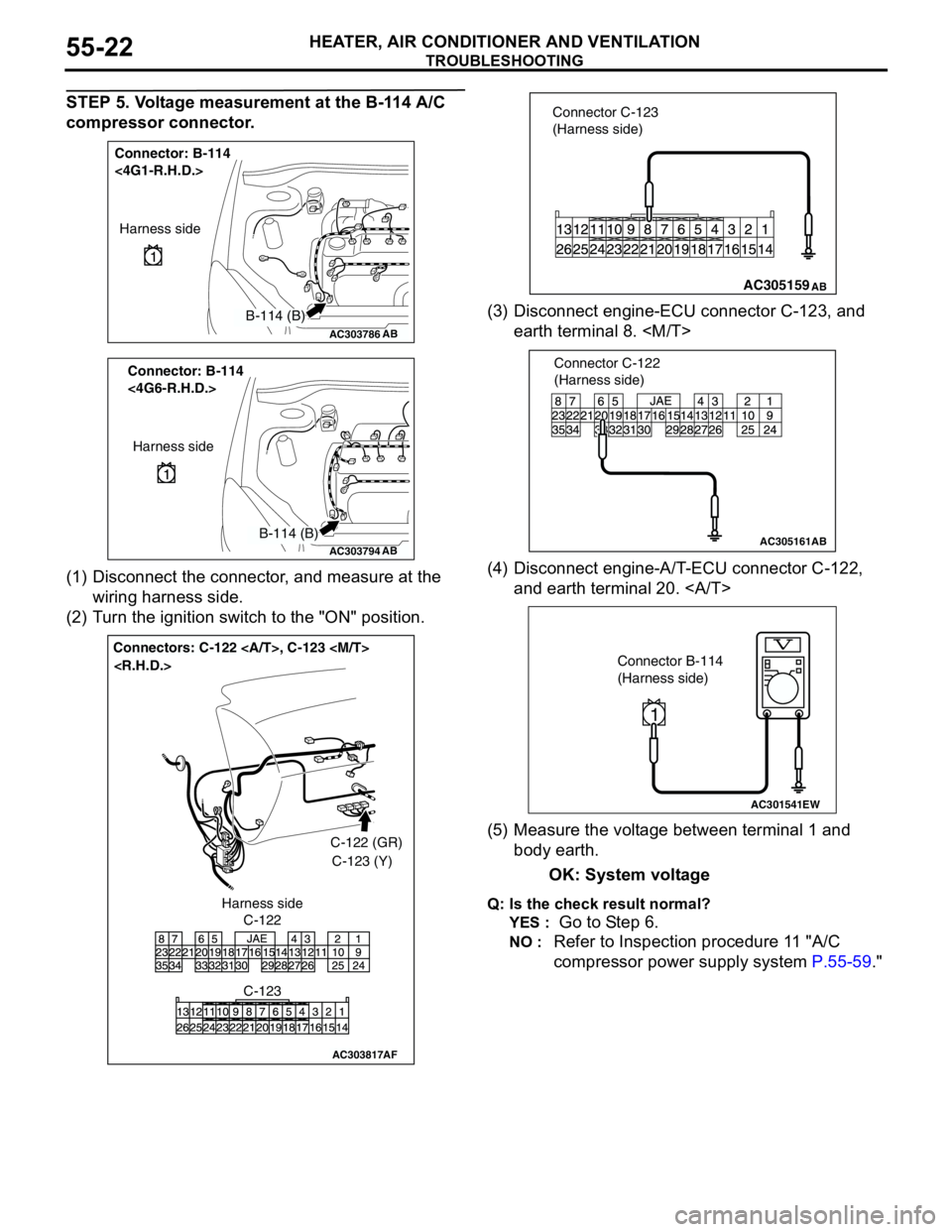
STEP 5. Voltage measurement at the B-114 A/C
compressor connector.
(1) Disconnect the connector, and measure at the
wiring harness side.
(2) Turn the ignition switch to the "ON" position.(3) Disconnect engine-ECU connector C-123, and
earth terminal 8.
(4) Disconnect engine-A/T-ECU connector C-122,
and earth terminal 20.
(5) Measure the voltage between terminal 1 and
body earth.
OK: System voltage
Q: Is the check result normal?
YES :
Go to Step 6.
NO : Refer to Inspection procedure 11 "A/C
compressor power supply system P.55-59."
AC303786
Connector: B-114
<4G1-R.H.D.>
AB
Harness side
B-114 (B)
AC303794
Connector: B-114
<4G6-R.H.D.>
AB
Harness side
B-114 (B)
AC303817
Connectors: C-122 , C-123
AF
C-122C-122 (GR)
C-123 (Y)
C-123 Harness side
AC305159 Connector C-123
(Harness side)AB
AC305161
Connector C-122
(Harness side)
AB
AC301541EW
Connector B-114
(Harness side)
1
Page 512 of 788
TROUBLESHOOTING
HEATER, AIR CONDITIONER AND VENTILATION55-28
STEP 19. Check the magnetic clutch operation.
Refer to P.55-93.
Q: Can the sound of the magnetic clutch (click) be
heard?
YES :
Go to Step 20.
NO : Replace the compressor magnet clutch.
STEP 20. Check the refrigerant temperature
switch.
Refer to P.55-95.
Q: Is the refrigerant temperature switch operating
properly?
YES :
Go to Step 21.
NO : Replace the refrigerant temperature switch.
STEP 21. Check the air thermo sensor.
Refer to P.55-90.
Q: Is the air thermo sensor in good condition?
YES :
Go to Step 22.
NO : Replace the air thermo sensor.
STEP 22. Check the refrigerant level.
Refer to P.55-69.
Q: Is the refrigerant level correct?
YES :
Go to Step 23.
NO : Correct the refrigerant level (Refer to
On-vehicle Service P.55-70).
STEP 23. Replace the A/C-ECU.
Check that the air conditioner works normally.
Q: Is the check result normal?
YES :
This diagnosis is complete.
NO : Replace the engine-ECU
engine-A/T-ECU .
Page 543 of 788
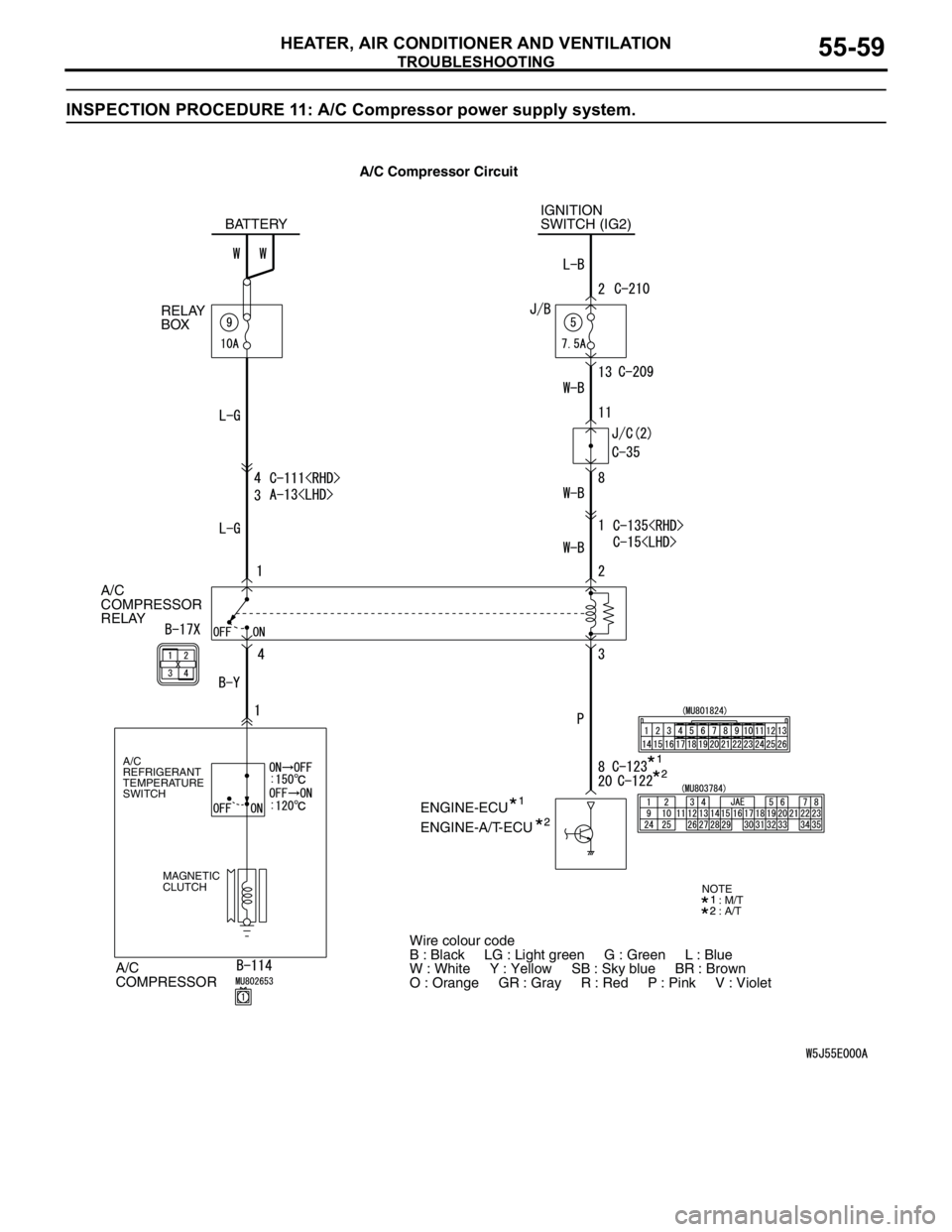
TROUBLESHOOTING
HEATER, AIR CONDITIONER AND VENTILATION55-59
INSPECTION PROCEDURE 11: A/C Compressor power supply system.
A/C
COMPRESSOR
RELAY
A/C
COMPRESSOR
A/C
REFRIGERANT
TEMPERATURE
SWITCH
MAGNETIC
CLUTCH
IGNITION
SWITCH (IG2)
ENGINE-ECU BATTERY
RELAY
BOX
ENGINE-A/T-ECU
Wire colour code
B : Black LG : Light green G : Green L : Blue
W : White Y : Yellow SB : Sky blue BR : Brown
O : Orange GR : Gray R : Red P : Pink V : Violet
: M/T
: A/TNOTE
A/C Compressor Circuit