ron MITSUBISHI LANCER 2006 Workshop Manual
[x] Cancel search | Manufacturer: MITSUBISHI, Model Year: 2006, Model line: LANCER, Model: MITSUBISHI LANCER 2006Pages: 800, PDF Size: 45.03 MB
Page 369 of 800
Rear wiper motor removal steps
•Tailgate trim lower (Refer to GROUP
52A, Tailgate trim
P.52A-21.)
•Tailgate waterproof film (Refer to
GROUP 42, Tailgate
P.42-48.)
3.Rear wiper motor assembly
Rear washer nozzle removal steps
•High-mounted stop lamp assembly
(Refer to GROUP 54A, High-mounted
stop lamp
P.54A-84.)
4.Rear washer nozzle
Washer hose removal steps
•Front scuff plate, rear scuff plate, cowl
side trim and quarter trim (Refer to
GROUP 52A, Trims
P.52A-13.)
•Tailgate lower trim, tailgate proof film
(Refer to GROUP 52A, Tailgate trim
P.52A-21.)
•High-mounted stop lamp assembly
(Refer to GROUP 54A, High-mounted
stop lamp
P.54A-84.)
5.Rear washer hose
REAR WIPE R AN D W A SHER
EXTERIOR51-37
NOTE: For re moval a nd in st allation of the wiper an d
washer switch, refer to GROUP 54A, Colu mn switch
P.5 4 A - 89.
INSTALLA T ION SER VICE POINT S
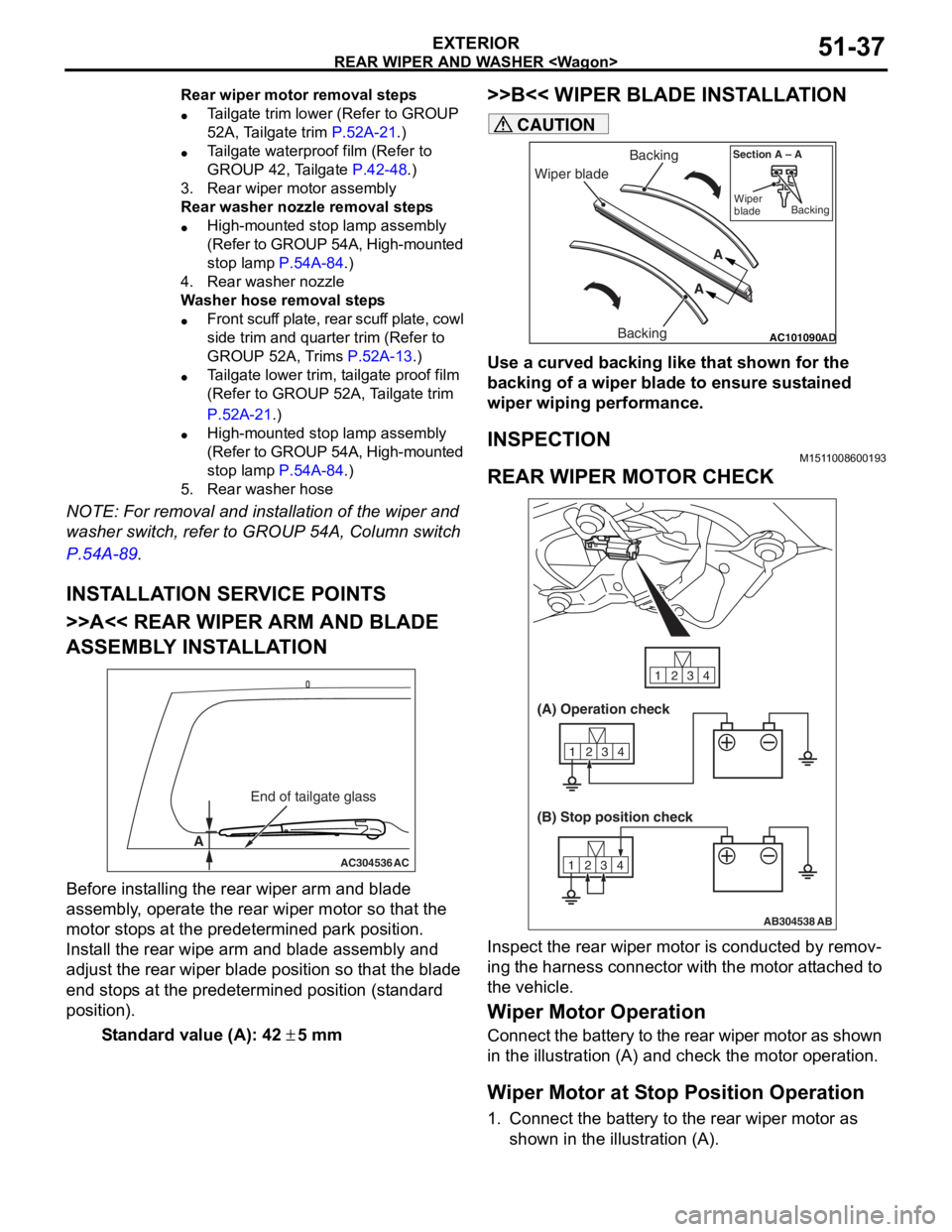
>>A<< REAR WIPER ARM AND BLADE
ASSEMBL
Y INST ALLA TION
AC304536
A
AC
End of tailgate glass
Before inst alling the rear wiper arm and blad e
assembly
, ope rate the rear wip e r mo tor so that th e
motor stop
s at the predete r min ed p a rk position .
Inst
all the re ar wipe arm a nd blade assembly and
adjust the
rear wipe r blad e positio n so t hat the blad e
end stop
s at the pre determined positio n (st anda rd
position
) .
St andard va lue (A): 42 ± 5 mm
>>B<< W I PER BLADE INST ALLA TION
AC101090AD
Wiper blade Backing
Backing A
A
Section A – A
Wiper
blade Backing
CAUTION
Use a curved backing like that shown for the
backing of a wiper blade to ensure sustained
wiper wiping performance.
INSPECTION
M1511008600193
REAR WIPER MOTOR CHECK
AB304538
1234
1234
1234
AB
(A) Operation check
(B) Stop position check
Inspect the rear wiper motor is conducted by remov-
ing the harness connector with the motor attached to
the vehicle.
Wiper Motor Operation
Connect the battery to the rear wiper motor as shown
in the illustration (A) and check the motor operation.
Wiper Motor at Stop Position Operation
1. Connect the battery to the rear wiper motor as
shown in the illustration (A).
Page 373 of 800
MARK
EXTERIOR51-41
MARK
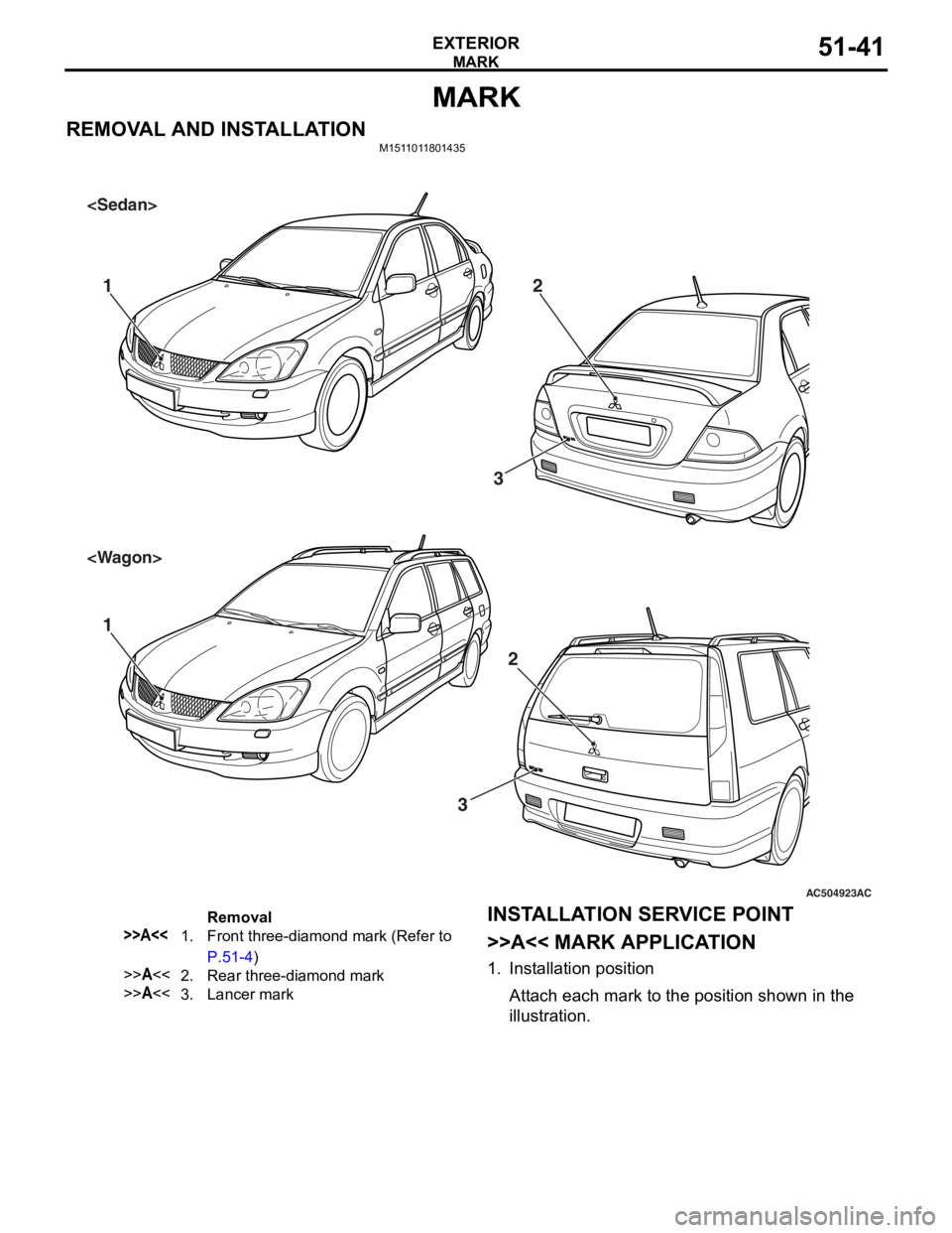
REMOVAL AND INSTALLATIONM1511011801435
AC504923
11 22
3
AC
3
Removal
>>A<<1.Front three-diamond mark (Refer to
P.51-4)
>>A<<2.Rear three-diamond mark
>>A<<3.Lancer mark
INST ALLA T ION SER VICE POINT
>>A<< MARK APPLICA T ION
1.In st allation positio n
Atta ch each ma rk to the po sition shown in the
i
llu strati on.
Page 377 of 800
DOOR MIRROR
EXTERIOR51-45
STEP 2. Connector check: C-212 junction block
connector
AC304913
21716151718
201912345
623 222425282627981011141213
Connector: C-212
Harness side
AB
Junction block (Front view)
Q: Is t h e che c k r esu lt n o rmal?
YES : Intermittent malfun ctio n (Refer to GROUP
00
− Ho w to Cope wit h Intermitte nt
Ma
lfunction
P.00-5).
NO : Repa ir th e defective connector .
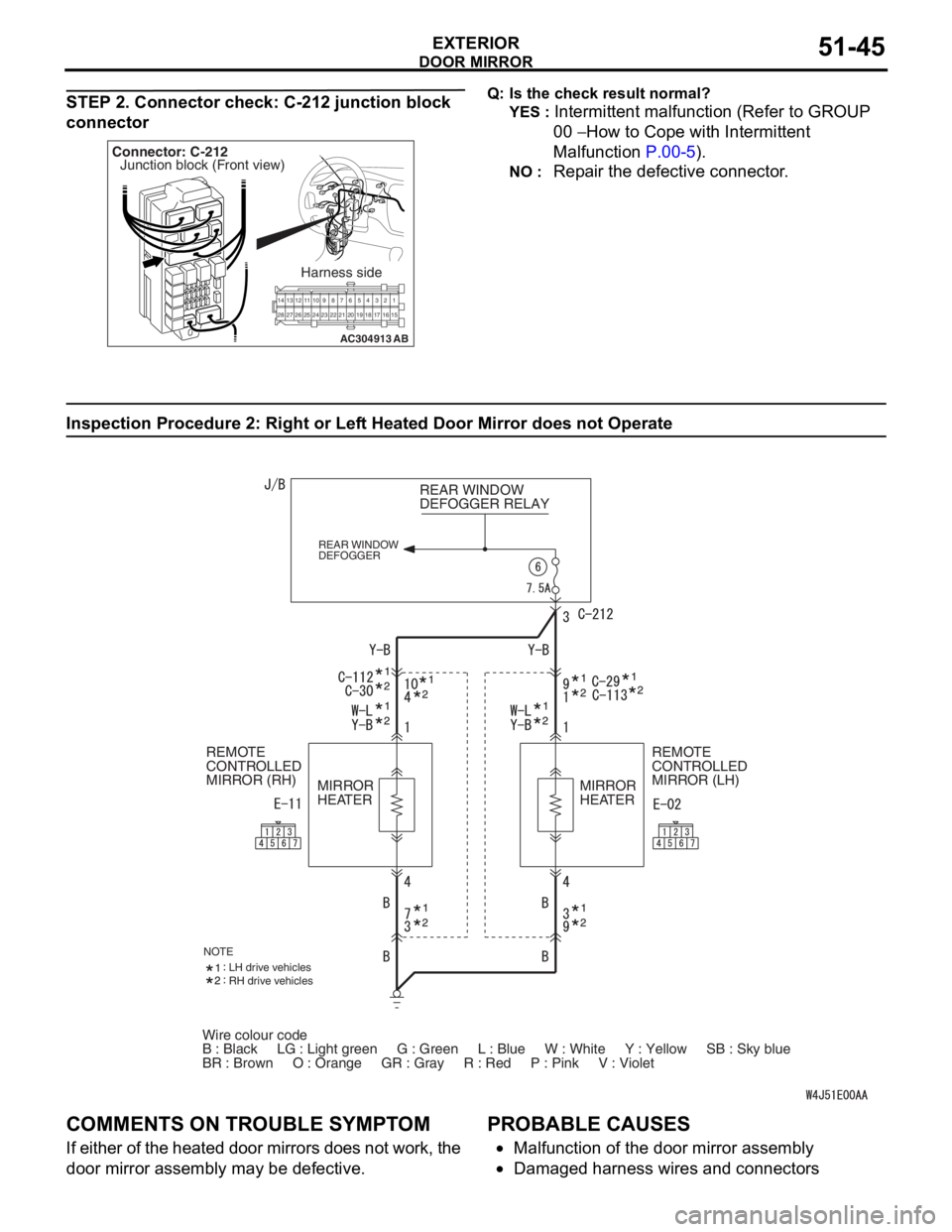
Inspection Procedure 2 : Ri ght or Lef t Hea t ed Door Mirror does not Operate
Wire colour code
B : Black LG : Light green G : Green L : Blue W : White \
Y : Yellow SB : Sky blue
BR : Brown O : Orange GR : Gray R : Red P : Pink V :\
Violet REAR WINDOW
DEFOGGER RELAY
REAR WINDOW
DEFOGGER
REMOTE
CONTROLLED
MIRROR (LH)
REMOTE
CONTROLLED
MIRROR (RH)
MIRROR
HEATER MIRROR
HEATER
NOTELH drive vehicles
RH drive vehicles
COMM
ENT S ON TROUBL E SYMPT O M
If eit her of t he hea ted d oor mirrors does n o t work, the
door mirror a
sse mbly may b e defe c tive.
PROBABLE CAUSES
•Malfunctio n of th e door mirro r assemb ly
•Damaged ha rness wires and con necto rs
Page 379 of 800
DOOR MIRROR
EXTERIOR51-47
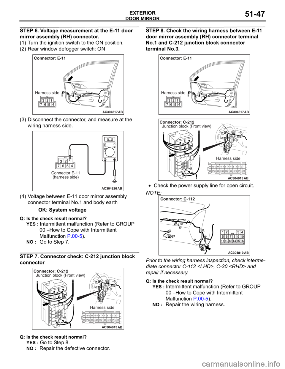
STEP 6. Voltage measurement at the E-11 door
mirror assembly (RH) connector.
(1) Turn the ignition switch to the ON position.
(2) Rear window defogger switch: ON
AC304817
Connector: E-11Harness side
AB
(3) D isconn ect t he co nnector , an d me asure at the
wiring harn e ss side.
AC304826
Connector E-11(harness side)
AB
(4) V olt a g e between E-1 1 door mirror assembly
co nnector termina l No.1 a nd bod y ea rth
OK: System vo lt age
Q: Is the check result normal?
YES : Intermittent ma lfun ctio n (Refer to GROUP
00
− Ho w t o Cope wit h Intermitte nt
Malfunction
P.00-5).
NO : Go to S t ep 7.
STEP 7. Co nnector ch eck: C-212 junction block
connecto
r
AC304913
21716151718
201912345
623 222425282627981011141213
Connector: C-212
Harness side
AB
Junction block (Front view)
Q : Is the check result normal?
YES : Go to S t ep 8.
NO : Repa ir the defective connector .
STEP 8 . Check the wiring harness b e twee n E-1 1
door mirror assem
bly (RH) conne ctor terminal
No.
1 and C-21 2 junctio n block connec tor
terminal No.3
.
AC304817
Connector: E-11
Harness side
AB
AC304913
21716151718
201912345
623 222425282627981011141213
Connector: C-212
Harness side
AB
Junction block (Front view)
•Check th e power supply line fo r open circuit.
NOTE:
AC304819
Connector: C-112
AB
Prior to the wiring harness insp ection, check interme-
diate connector C-1 1 2
rep
a ir if necessary .
Q:Is t h e che c k r esu lt n o rmal?
YES : Intermittent malfun ctio n (Refer to GROUP
00
− Ho w to Cope wit h Intermitte nt
Ma
lfunction
P.00-5).
NO : Repa ir th e wirin g harne ss.
Page 381 of 800
DOOR MIRROR
EXTERIOR51-49
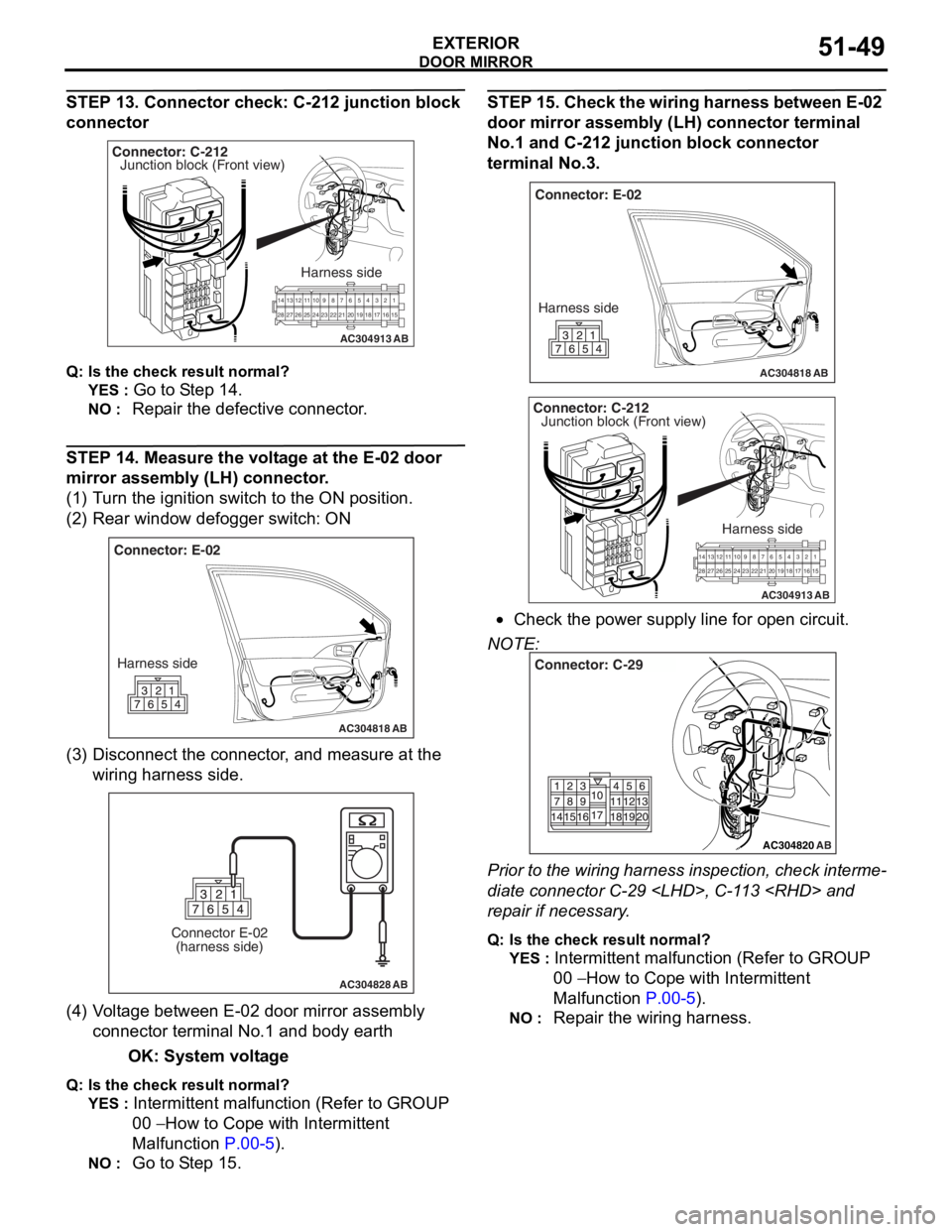
STEP 13. Connector check: C-212 junction block
connector
AC304913
21716151718
201912345
623 222425282627981011141213
Connector: C-212
Harness side
AB
Junction block (Front view)
Q : Is the check result normal?
YES : Go to S t ep 14 .
NO : Repa ir the defective connector .
STEP 14 . Me asure the volt age at the E-02 door
mirror a
ssembl y (LH) conne ctor .
(1)T urn t he ig nition switch to the ON positio n.
(2)R ear win dow defo gger switch : ON
AC304818
Connector: E-02
Harness side
AB
(3) D isconn ect t he co nnector , an d me asure at the
wiring harn e ss side.
AC304828
Connector E-02(harness side)
AB
(4) V olt a g e between E-02 doo r mirror assembly
co nnector termina l No.1 a nd bod y ea rth
OK: System vo lt age
Q: Is the check result normal?
YES : Intermittent ma lfun ctio n (Refer to GROUP
00
− Ho w t o Cope wit h Intermitte nt
Malfunction
P.00-5).
NO : Go to S t ep 15 .
STEP 1 5 . Chec k the wiring ha rnes s betwe en E-02
door mirror assem
bly (LH) con nector termina l
No.
1 and C-21 2 junctio n block connec tor
terminal No.3
.
AC304818
Connector: E-02
Harness side
AB
AC304913
21 716151718
201912345
623 222425282627981011141213
Connector: C-212
Harness side
AB
Junction block (Front view)
•Check th e power supply line fo r open circuit.
NOTE:
AC304820
Connector: C-29
AB
Prior to the wiring harness insp ection, check interme-
diate connector C-29
rep
a ir if necessary .
Q:Is t h e che c k r esu lt n o rmal?
YES : Intermittent malfun ctio n (Refer to GROUP
00
− Ho w to Cope wit h Intermitte nt
Ma
lfunction
P.00-5).
NO : Repa ir th e wirin g harne ss.
Page 383 of 800
DOOR MIRROR
EXTERIOR51-51
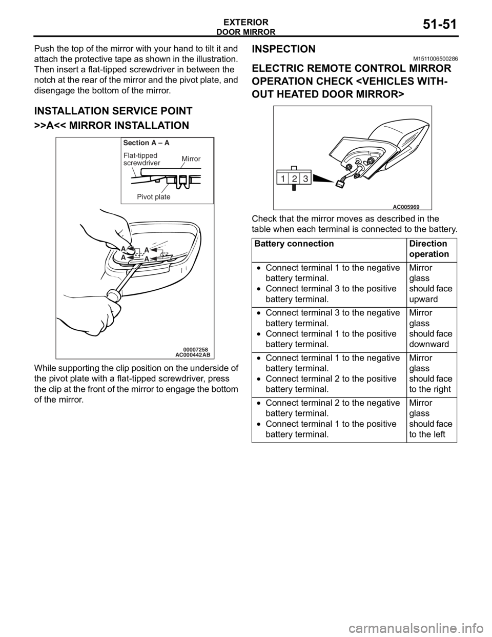
Push the top of the mirror with your hand to tilt it and
attach the protective tape as shown in the illustration.
Then insert a flat-tipped screwdriver in between the
notch at the rear of the mirror and the pivot plate, and
disengage the bottom of the mirror.
INSTALLATION SERVICE POINT
>>A<< MIRROR INSTALLATION
AC00044200007258
Mirror
Flat-tipped
screwdriver
Section A – A
Pivot plate
A
A A
A
AB
W h il e su pp ort i ng t he clip po siti on on th e u nde rsi de of
the pivot p
l ate with a flat -tipped screwdr i ver , press
t
he clip at th e front of the mirror t o engage t he botto m
of the mirro
r .
INSPECTION
M151 1 0065 0028 6
ELECTRIC REMOTE CONTROL MIRROR
OPERA
T ION CHECK < V EHICLES WITH
-
OUT HEAT ED DOOR MIRROR>
3
2
1
AC005969
Ch eck that th e mirror moves as describe d in the
t
a b l e when each terminal is conn ecte d to the batte ry .
Battery connectionDirection
operation
•Connect terminal 1 to the negative
battery terminal.
•Connect terminal 3 to the positive
battery terminal.
Mirror
glass
should face
upward
•Connect terminal 3 to the negative
battery terminal.
•Connect terminal 1 to the positive
battery terminal.
Mirror
glass
should face
downward
•Connect terminal 1 to the negative
battery terminal.
•Connect terminal 2 to the positive
battery terminal.
Mirror
glass
should face
to the right
•Connect terminal 2 to the negative
battery terminal.
•Connect terminal 1 to the positive
battery terminal.
Mirror
glass
should face
to the left
Page 392 of 800
ECU
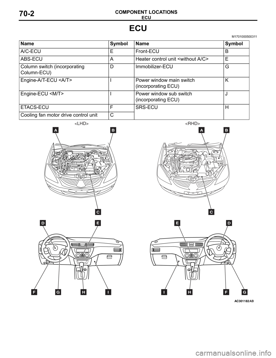
COMPONENT LOCATIONS70-2
ECU
M1701000500311
NameSymbolNameSymbol
A/C-ECUEFront-ECUB
ABS-ECUAHeater control unit
Column switch (incorporating
Column-ECU)DImmobilizer-ECUG
Engine-A/T-ECU IPower window main switch
(incorporating ECU)K
Engine-ECU
(incorporating ECU)J
ETACS-ECUFSRS-ECUH
Cooling fan motor drive control unitC
AC301182
DE
AB
C
FGHI
AB
DE
AB
C
FGHI
Page 393 of 800
AC304537
JK*
AE
ECU
COMPONENT LOCA TIONS70-3
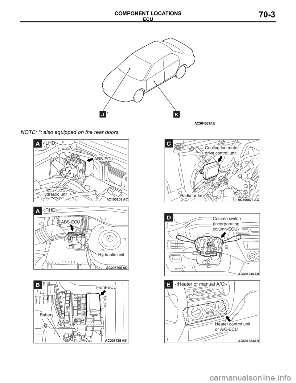
NOTE: *: also eq uipp ed on the rear doors.
AC100209AC
A
ABS-ECU
Hydraulic unit
AC206790
A
AD
ABS-ECU
Hydraulic unit
AC301728AB
BFront-ECU
Battery
AC300571
C
ACRadiator fan
Cooling fan motor
drive control unit
AC301746
DColumn switch
(incorporating
column-ECU)
AB
AC501783AB
E
Heater control unit
or A/C-ECU
Page 395 of 800
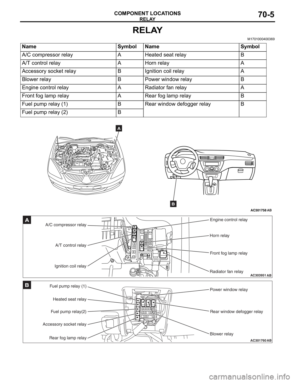
RELAY
COMPONENT LOCATIONS70-5
RELAY
M1701000400369
NameSymbolNameSymbol
A/C compressor relayAHeated seat relayB
A/T control relayAHorn relayA
Accessory socket relayBIgnition coil relayA
Blower relayBPower window relayB
Engine control relayARadiator fan relayA
Front fog lamp relayARear fog lamp relayB
Fuel pump relay (1)BRear window defogger relayB
Fuel pump relay (2)B
AC301758AB
A
B
AC303951AB
A/C compressor relayEngine control relay
Horn relay
Front fog lamp relay
Radiator fan relay
A/T control relay
Ignition coil relayA
AC301760
Fuel pump relay (1) Power window relay
Rear window defogger relay
Blower relay
Heated seat relay
Fuel pump relay(2)
Accessory socket relay
Rear fog lamp relayAB
B
Page 396 of 800
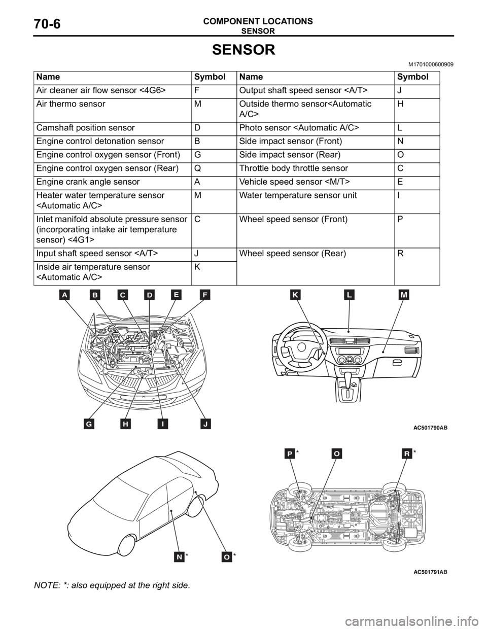
SENSOR
COMPONENT LOCATIONS70-6
SENSOR
M1701000600909
NameSymbolNameSymbol
Air cleaner air flow sensor <4G6>FOutput shaft speed sensor J
Air thermo sensorMOutside thermo sensor
Camshaft position sensorDPhoto sensor
Engine control detonation sensorBSide impact sensor (Front)N
Engine control oxygen sensor (Front)GSide impact sensor (Rear)O
Engine control oxygen sensor (Rear)QThrottle body throttle sensorC
Engine crank angle sensorAVehicle speed sensor
Heater water temperature sensor
Inlet manifold absolute pressure sensor
(incorporating intake air temperature
sensor) <4G1>CWheel speed sensor (Front)P
Input shaft speed sensor JWheel speed sensor (Rear)R
Inside air temperature sensor
AC501790
BDCFEA
GHIJ
MKL
AB
AC501791AB
NO
POR
** *
*
NO
TE: *: also eq uipp ed at t he rig h t side.