ron MITSUBISHI LANCER 2006 Workshop Manual
[x] Cancel search | Manufacturer: MITSUBISHI, Model Year: 2006, Model line: LANCER, Model: MITSUBISHI LANCER 2006Pages: 800, PDF Size: 45.03 MB
Page 331 of 800
KEYLESS ENTRY SYSTEM
BODY42-59
REASSEMBLY SERVICE POINT
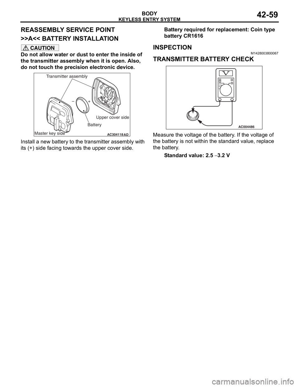
>>A<< BATTERY INSTALLATION
CAUTION
Do not allow water or dust to enter the inside of
the transmitter assembly when it is open. Also,
do not touch the precision electronic device.
AC304118AD
+
–
Master key side Upper cover side
Battery
Transmitter assembly
Install a new battery to the transmitter assembly with
its (+) side facing towards the upper cover side.
Battery required for replacement: Coin type
battery CR1616
INSPECTION
M1428003800067
TRANSMITTER BATTERY CHECK
AC004486
Measure the voltage of the battery. If the voltage of
the battery is not within the standard value, replace
the battery.
Standard value: 2.5 − 3.2 V
Page 333 of 800
51-1
GROUP 51
EXTERIOR
CONTENTS
FRONT BUMPER ASSEMBLY . . . . .51-3
ADHESIVE . . . . . . . . . . . . . . . . . . . . . . . . . 51-3
FRONT BUMPER ASSEMBLY . . . . . . . . . . 51-3
REMOVAL AND INSTALLATION . . . . . . . . 51-3
DISASSEMBLY AND REASSEMBLY . . . . . 51-4
REAR BUMPER ASSEMBLY . . . . . .51-6
REMOVAL AND INSTALLATION . . . . . . . . 51-6
DISASSEMBLY AND REASSEMBLY . . . . . 51-7
MOULDINGS . . . . . . . . . . . . . . . . . . .51-8
SPECIAL TOOL . . . . . . . . . . . . . . . . . . . . . 51-8
ADHESIVE . . . . . . . . . . . . . . . . . . . . . . . . . 51-9
MOULDINGS . . . . . . . . . . . . . . . . . . . . . . . 51-9
REMOVAL AND INSTALLATION . . . . . . . . 51-9
SIDE AIR DAM . . . . . . . . . . . . . . . . . .51-14
ADHESIVE . . . . . . . . . . . . . . . . . . . . . . . . . 51-14
SIDE AIR DAM . . . . . . . . . . . . . . . . . . . . . . 51-14
REMOVAL AND INSTALLATION . . . . . . . . 51-14
GARNISHES . . . . . . . . . . . . . . . . . . .51-16
REMOVAL AND INSTALLATION . . . . . . . . 51-16
DOOR SASH TAPE . . . . . . . . . . . . . .51-17
SPECIAL TOOL . . . . . . . . . . . . . . . . . . . . . 51-17
DOOR SASH TAPE . . . . . . . . . . . . . . . . . . 51-17
REMOVAL AND INSTALLATION
REMOVAL AND INSTALLATION
REAR SPOILER
REMOVAL AND INSTALLATION . . . . . . . . 51-25
TAILGATE SPOILER
REMOVAL AND INSTALLATION . . . . . . . . 51-26
ROOF RAIL
REMOVAL AND INSTALLATION . . . . . . . . 51-27
WINDSHIELD WIPER AND
WASHER. . . . . . . . . . . . . . . . . . . . . . .51-28
GENERAL INFORMATION . . . . . . . . . . . . . 51-28
SERVICE SPECIFICATION . . . . . . . . . . . . 51-28
SPECIAL TOOLS . . . . . . . . . . . . . . . . . . . . 51-29
TROUBLESHOOTING . . . . . . . . . . . . . . . . 51-30
ON-VEHICLE SERVICE . . . . . . . . . . . . . . . 51-30
WINDSHIELD WIPER AND WASHER . . . . 51-31
REMOVAL AND INSTALLATION . . . . . . . . 51-31
INSPECTION. . . . . . . . . . . . . . . . . . . . . . . . 51-33
REAR WIPER AND WASHER
GENERAL INFORMATION . . . . . . . . . . . . . 51-35
SERVICE SPECIFICATION . . . . . . . . . . . . 51-35
TROUBLESHOOTING . . . . . . . . . . . . . . . . 51-36
ON-VEHICLE SERVICE . . . . . . . . . . . . . . . 51-36
REAR WIPER AND WASHER . . . . . . . . . . 51-36
REMOVAL AND INSTALLATION . . . . . . . . 51-36
INSPECTION. . . . . . . . . . . . . . . . . . . . . . . . 51-37
Continued on next page
Page 335 of 800
FRONT BUMPER ASSEMBLY
EXTERIOR51-3
FRONT BUMPER ASSEMBLY
ADHESIVEM1511000501195
ItemSpecification
Front three-diamond markDouble-sided tape: Generic products
0.8 mm thickness
FRONT BUMPER ASSEMBLY
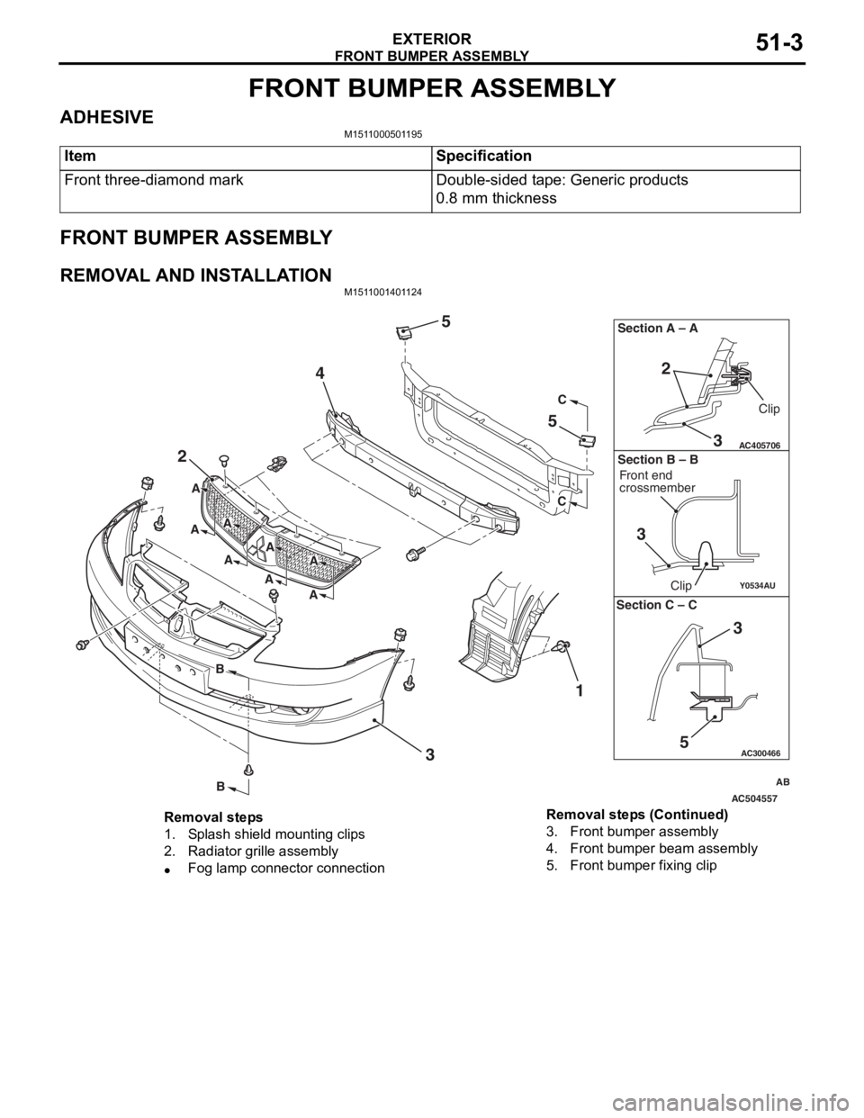
REMOVAL AND INSTALLATIONM1511001401124
AC504557
AC300466
Y0534AU
AC405706
AB
2
4
5
5
3 1
C
C
B
B
A
A
A
AA
A
A
A
3
2
Section A – A
3
Clip
Front end
crossmember
Clip
Section B – B
5
3
Section C – C
Removal steps
1.Splash shield mounting clips
2.Radiator grille assembly
•Fog lamp connector connection
3.Front bumper assembly
4.Front bumper beam assembly
5.Front bumper fixing clip
Removal steps (Continued)
Page 336 of 800
FRONT BUMPER ASSEMBLY
EXTERIOR51-4
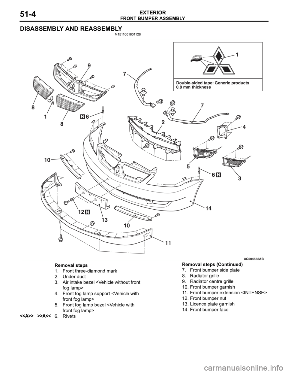
DISASSEMBLY AND REASSEMBLY
M1511001601128
AC504558AB
Double-sided tape: Generic products
0.8 mm thickness
1
1
12
13
14
11
10
10
4
7
7
6
6
8
9
8
5
3N
N
N
2
Removal steps
1.Front three-diamond mark
2.Under duct
3.Air intake bezel
4.Front fog lamp sup port
5.Front fog lamp bezel
<>>>A<<6.Rivets
7.Front bumper side plate
8.Radiator grille
9.Radiator centre grille
10.Front bumper garnish
11 .Front bumper extension
12.Front bumper nut
13.Licence plate garnish
14.Front bumper face
Removal steps (Continued)
Page 337 of 800

Page 341 of 800
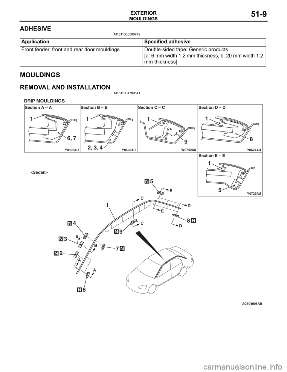
MOULDINGS
EXTERIOR51-9
ADHESIVE
M1511000500749
ApplicationSpecified adhesive
Front fender, front and rear door mouldingsDouble-sided tape: Generic products
[a: 6 mm width 1.2 mm thickness, b: 20 mm width 1.2
mm thickness]
MOULDINGS
REMOVAL AND INSTALLATIONM1511004700541
AC504995
Y0622AU
Y0624AUY0623AU
Y0729AU
W0740AU
Section A – A
DRIP MOULDINGS
Section B – B Section C – C Section D – D
Section E – E
AB
N
N
N
N
N
CC
E E
D
D
B
B
A
A
1
2
6
4
3
5
7
8
9
N
N
N
111
9 8
51
1
6, 7 2, 3, 4
Page 342 of 800
AC304340
1
1
AA
AA
AB
B
B
C
C
C
C
B B
N
N
N
2
N2
4
3
N3
N4
N
6
9
7
N
6N
N
7N
N9
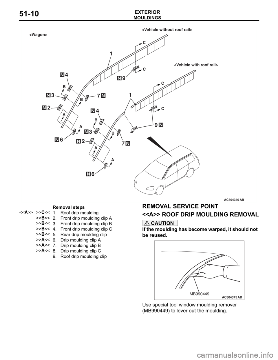
Removal steps
<>>>C<<1.Roof drip moulding
>>B<<2.Front drip moulding clip A
>>B<<3.Front drip moulding clip B
>>B<<4.Front drip moulding clip C
>>B<<5.Rear drip moulding clip
>>A<<6.Drip moulding clip A
>>A<<7.Drip moulding clip B
>>A<<8.Drip moulding clip C
9.Roof drip moulding clip
MO
UL DI N G S
EXTERIOR51-10
REMOVA L SER VICE POINT
<> ROOF DRIP MOULDING REMOV A L
CAUTION
If the moulding has become warped, it should not
be reused.
AC304375MB990449AB
Use special tool window moulding remover
(MB990449) to lever out the moulding.
Page 343 of 800
MOULDINGS
EXTERIOR51-11
INSTALLATION SERVICE POINTS
>>A<< DRIP MOULDING CLIP C/DRIP
MOULDING CLIP B/DRIP MOULDING
CLIP A INSTALLATION
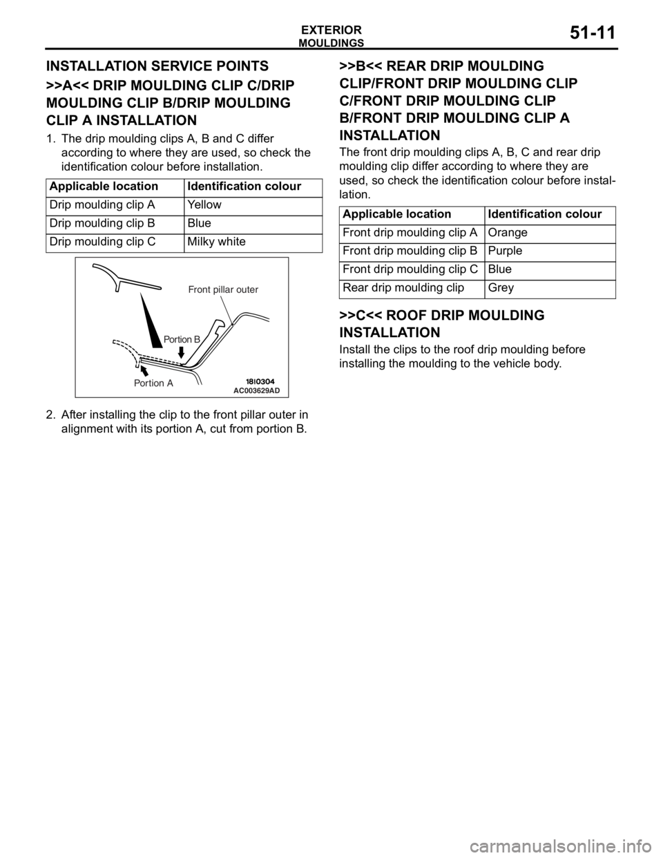
1. The drip moulding clips A, B and C differ according to where they are used, so check the
identification colour before installation.
Applicable locationIdentification colour
Drip moulding clip AYe l l o w
Drip moulding clip BBlue
Drip moulding clip CMilky white
AC003629
Front pillar outer
Portion B
Portion AAD
2. Af ter inst alling the clip to the f r ont pilla r outer in
align m ent with it s portio n A, cu t from portion B.
>>B<< REAR DRIP MOULDING
CLIP/FRONT DRIP MOULDING CLIP
C/FRONT DRIP MOULDING CLIP
B/FRONT DRIP MOULDING CLIP A
INST
ALLA TION
The front drip mou l din g clip s A, B, C an d rear d r ip
moulding
clip dif f er accordin g to where they are
used
, so check th e ide n tification colou r before inst al
-
lation.
Applicable locationIdentification colour
Front drip moulding clip AOrange
Front drip moulding clip BPurple
Front drip moulding clip CBlue
Rear drip moulding clipGrey
>>C<< ROOF DRIP MOULDING
INSTALLA TION
Install the clip s to th e roof d r ip mould i ng before
inst
allin g the moulding to the vehicle body .
Page 344 of 800
AC504986 AC400117
AC400128
Section A – A
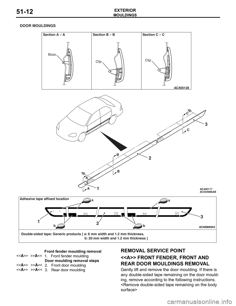
DOOR MOULDINGS
Section B – B Section C – C
AB
AA C
C
BB2
1
3
ClipClip
Boss
AC400840AE
Double-sided tape: Generic products [ a: 6 mm width and 1.2 mm thickness, b: 20 mm width and 1.2 mm thickness ]
12
3
a
b
baAdhesive tape affixed location
Front fender moulding removal
<>>>A<<1.Front fender moulding
Door moulding removal steps
<>>>A<<2.Front door moulding
<>>>A<<3.Rear door moulding
MO
UL DI N G S
EXTERIOR51-12
REMOVA L SER VICE POINT
<> FRONT FENDER, FRONT AND
REAR DOOR MOULDINGS REMOV
A L
Gently lif t and remo ve th e door moulding . If the r e is
any d
ouble-sided t ape remainin g on th e door mould
-
ing, remove accord ing to the fo llowing in struction s .
Page 345 of 800
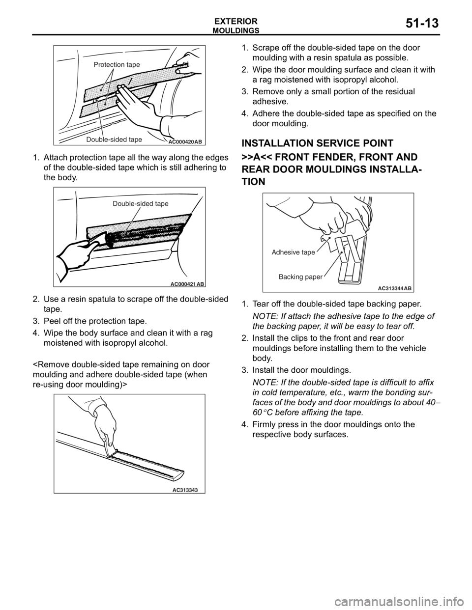
AC000420Double-sided tapeProtection tapeAB
MO
UL DI N G S
EXTERIOR51-13
1.At t a ch pro t ection t a pe all th e wa y alon g the e dge s
of the do uble - sid ed t ape which is still adh ering to
th e body .
AC000421
Double-sided tape
AB
2.Use a resin sp atula to scrape of f t he dou ble-sided
t ape .
3.Pee l of f the pr otect i on t ape .
4.Wipe th e body su rface and clean it with a rag
moistened with isopro p yl alcohol.
and a dhere d ouble-sided t ape (wh en
re-using do
or mo ulding)>
AC313343
1.Scrape o f f the double-sided t ape on th e door
moulding with a re sin sp atula as possible.
2.Wipe th e door moulding surfa c e a nd clean it with
a rag moistened with isoprop yl a l co hol.
3.Remove only a small po rtion o f the re sid ual
a dhesive .
4.Adh e re the double-sided t ape as specified on t he
d oor mo ulding.
INSTALLA T ION SER VICE POINT
>>A<< FRONT FENDER, FRONT AND
REAR DOOR MOULDINGS INST
ALLA
-
TION
AC313344
Backing paper
Adhesive tape
AB
1.
T ear of f the double-sided t ape backing p aper .
NOTE: If atta ch the adhesive t a pe to the edg e of
th
e backing p aper , it will be easy to te ar off.
2.In st all the clip s to the front a nd rear door
mouldings befo r e inst alling th em to the vehicle
b ody .
3.In st all the do or mo uldings.
NOTE: If the double-sided t ape is difficult to af fix
in co
ld te mpera t ure, et c., warm the b ondin g su r
-
faces of the bod y and doo r mo uldin g s to ab out 40−
60
°C bef ore affixing the t a p e .
4.Firmly pre ss in the door moulding s ont o the
re spective bod y surface s .