sensor MITSUBISHI LANCER EVOLUTION 2007 Service Repair Manual
[x] Cancel search | Manufacturer: MITSUBISHI, Model Year: 2007, Model line: LANCER EVOLUTION, Model: MITSUBISHI LANCER EVOLUTION 2007Pages: 1449, PDF Size: 56.82 MB
Page 655 of 1449

MPI -Troubleshooting13A-123
IGNITION COIL AND POWER TRANSISTOR
DIgnition coil primary signal
Refer to GROUP 16 - Ignition system.
DPower transistor control signal
Measurement Method
1. Disconnect the ignition coil connector, and connect the
special tool (test harness: MB991658) in between. (All
terminals should be connected.)
2. Connect the analyzer special patterns pickup to terminal
No. 3 of each ignition coil connector in turn.
Alternate Method (Test harness not available)
1. Connect the analyzer special patterns pickup to
engine-ECU terminal No. 10 (No. 1 - No. 4), terminal
No. 23 (No. 2 - No. 3) respectively.
Standard Wave Pattern
Observation condition
FunctionSpecial patterns
Pattern heightLow
Pattern selectorDisplay
Engine r/minApproximately 1,200 r/min
Standard wave pattern
Crank angle
sensor output
wave pattern
Power transistor
control signal
wave pattern(V)
75_BTDC5_BTDCT: Revolution time corresponding to a crank angle of 180_
Compression top dead center
θ: Spark
advance
angleIgnition period
OFF ON
Dwell section
T1: Time computed by the engine-ECUTime θ T1T
6
4
2
0
4
2
0
Special
patterns
pickupAnalyzer
Page 658 of 1449

MPI -On-vehicle Service13A-126
THROTTLE BODY (THROTTLE VALVE AREA)
CLEANING
1. Remove the air intake hose from the throttle body.
2. Spray cleaning fluid on a clean cloth.
3. Wipe off the dirt around the throttle valve with the cloth
sprayed with cleaning fluid.
Caution
(1) Do not spray the cleaning fluid directly to the
throttle valve.
(2) Make sure the cleaning fluid does not enter the
motor from the bypass line. Also make sure it
does not enter the sensor through the shaft.
(3) Be careful not to rub off the molybden applied
around the throttle valve shaft.
4. Attach the air intake hose.
5. Adjust the basic idle speed. (Refer to P.13A-127.)
THROTTLE POSITION SENSOR ADJUSTMENT
1. Connect the MUT-IIto the diagnosis connector.
When not using the MUT-II, proceed as follows:
(1) Disconnect the throttle position sensor connector, and
connect the special tool (test harness: MB991536)
between the disconnected connector taking care not
to confuse the terminal to be connected.
(2) Connect digital voltmeter between the terminal No.
2 and the terminal No. 4 of the throttle position sensor
connector.
2. Turn the ignition switch to “ON” position (but do not start
the engine).
3. Check the output voltage of the throttle position sensor.
Standard value: 535 - 735 mV
Throttle valve molybdenum
application section15 mm
15 mm
Equipment side connectorThrottle
position
sensor
Throttle
body
MB991536
Throttle position sensor
Page 659 of 1449

MPI -On-vehicle Service13A-127
4. If not within the standard value, loosen the throttle position
sensor mounting bolts. Then rotate the sensor body to
adjust.
5. Turn the ignition switch to “LOCK” (OFF) position.
6. Remove the MUT-II. If the MUT-IIis not used, remove
the special tool, and then connect the throttle position
sensor connector.
7. If a diagnosis code is displayed, erase the diagnosis code
by using the MUT-IIor disconnect the negative battery
cable from the battery terminal and then leave it for at
least ten seconds. After that, reconnect the battery cable,
and then let the engine run at idle for approximately 10
minutes.
BASIC IDLE SPEED ADJUSTMENT
NOTE
(1) The basic idling speed has been adjusted by the
speed adjusting screw by the manufacturer, and there
should usually be no need for readjustment.
(2) If the adjustment has been changed by mistake, the
idle speed may become too high or the idle speed
may drop too low when loads from components such
as the A/C are placed on the engine. If this occurs,
adjust by the following procedure.
(3) The adjustment, if made, should be made after first
confirming that the spark plugs, the injectors, the idle
speed control servo, the compression pressure, etc.,
are all normal.
1. Before inspection and adjustment, set the vehicle to the
pre-inspection condition.
2. Connect the MUT-IIto the diagnosis connector (16-pin).
NOTE
When the MUT-IIis connected, the diagnosis control
terminal should be earthed.
3. Start the engine and run at idle.
4. Select the item No. 30 of the MUT-IIActuator test.
NOTE
This holds the idle speed control servo at the basic step
to adjust the basic idle speed.
5. Check the basic idle speed.
Standard value: 850±100 r/min
NOTE
(1) The engine speed may be 20 to 100 r/min lower
than indicated above for a new vehicle [driven
approximately 500 km or less], but no adjustment
is necessary.
(2) If the engine stalls or the engine speed is low even
though the vehicle has been driven approximately
500 km or more, it is probable that deposits are
adhered to the throttle valve, so clean it. (Refer to
P.13A-126.)
Page 663 of 1449

MPI -On-vehicle Service13A-131
COMPONENT LOCATION
NameSymbolNameSymbol
A/C relayJFuel pump relay 1, 2Q
A/C switchTFuel pump relay 3H
Air flow sensor (integrated intake air tempera-
ture sensor and barometric pressure sensor)OFuel pump resistorH
Camshaft position sensorNIdle speed control servo (stepper motor)G
Crank angle sensorKIgnition coil (integrated power transister)M
Detonation sensorEInjectorC
Diagnosis connectorSOxygen sensor (front)L
EGR control solenoid valveDOxygen sensor (rear)X
Engine control relayIPower steering fluid pressure switchA
Engine coolant temperature sensorNResistor (for injector)H
Engine warning lamp (check engine lamp)RSecondary air control solenoid valveD
Engine-ECUUThrottle position sensorG
Fan motor relayJVehicle speed sensorF
Fuel pressure control solenoid valveBWaste gate solenoid valveP
ABCDEFGHIJK
LMNOP
QRSTU
Page 664 of 1449

MPI -On-vehicle Service13A-132
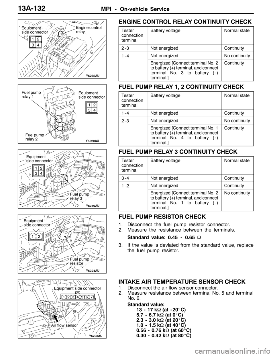
ENGINE CONTROL RELAY CONTINUITY CHECK
Tester
connection
terminalBattery voltageNormal state
2-3Not energizedContinuity
1-4Not energizedNo continuity
Energized [Connect terminal No. 2
to battery (+) terminal, and connect
terminal No. 3 to battery ( - )
terminal.]Continuity
FUEL PUMP RELAY 1, 2 CONTINUITY CHECK
Tester
connection
terminalBattery voltageNormal state
1-4Not energizedContinuity
2-3Not energizedNo continuity
Energized [Connect terminal No. 1
to battery (+) terminal, and connect
terminal No. 4 to battery ( - )
terminal.]Continuity
FUEL PUMP RELAY 3 CONTINUITY CHECK
Tester
connection
terminalBattery voltageNormal state
3-4Not energizedContinuity
1-2Not energizedContinuity
Energized [Connect terminal No. 2
to battery (+) terminal, and connect
terminal No. 1 to battery ( - )
terminal.]No continuity
FUEL PUMP RESISTOR CHECK
1. Disconnect the fuel pump resistor connector.
2. Measure the resistance between the terminals.
Standard value: 0.45 - 0.65Ω
3. If the value is deviated from the standard value, replace
the fuel pump resistor.
INTAKE AIR TEMPERATURE SENSOR CHECK
1. Disconnect the air flow sensor connector.
2. Measure resistance between terminal No. 5 and terminal
No. 6.
Standard value:
13 - 17 kΩ(at - 20_C)
5.7 - 6.7 kΩ(at 0_C)
2.3 - 3.0 kΩ(at 20_C)
1.0 - 1.5 kΩ(at 40_C)
0.56 - 0.76 kΩ(at 60_C)
0.30 - 0.42 kΩ(at 80_C)
Equipment
side connectorEngine control
relay
1
32
4
Equipment
side connector Fuel pump
relay 1
Fuel pump
relay 21
32
4
Equipment
side connector
Fuel pump
relay 3 1
32
4
Equipment
side connector
Fuel pump
resistor 12
Air flow sensor
Equipment side connector
123456 7
Page 665 of 1449

MPI -On-vehicle Service13A-133
3. Measure resistance while heating the sensor using a hair
drier.
Normal condition:
Temperature (_C)Resistance (kΩ)
HigherSmaller
4. If the value deviates from the standard value or the
resistance remains unchanged, replace the air flow sensor
assembly.
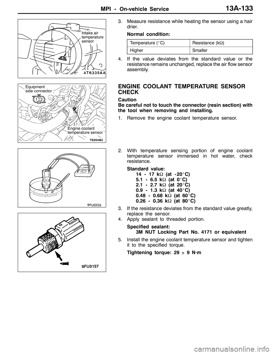
ENGINE COOLANT TEMPERATURE SENSOR
CHECK
Caution
Be careful not to touch the connector (resin section) with
the tool when removing and installing.
1. Remove the engine coolant temperature sensor.
2. With temperature sensing portion of engine coolant
temperature sensor immersed in hot water, check
resistance.
Standard value:
14 - 17 kΩ(at - 20_C)
5.1 - 6.5 kΩ(at 0_C)
2.1 - 2.7 kΩ(at 20_C)
0.9 - 1.3 kΩ(at 40_C)
0.48 - 0.68 kΩ(at 60_C)
0.26 - 0.36 kΩ(at 80_C)
3. If the resistance deviates from the standard value greatly,
replace the sensor.
4. Apply sealant to threaded portion.
Specified sealant:
3M NUT Locking Part No. 4171 or equivalent
5. Install the engine coolant temperature sensor and tighten
it to the specified torque.
Tightening torque: 29±9 N·m
Intake air
temperature
sensor
Engine coolant
temperature sensor
Equipment
side connector
12
Page 666 of 1449

MPI -On-vehicle Service13A-134
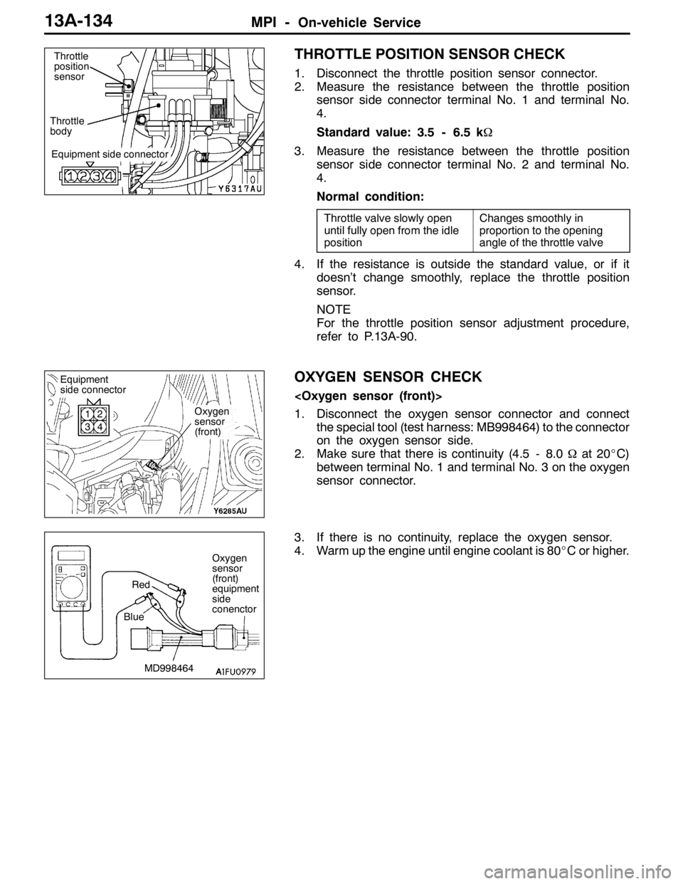
THROTTLE POSITION SENSOR CHECK
1. Disconnect the throttle position sensor connector.
2. Measure the resistance between the throttle position
sensor side connector terminal No. 1 and terminal No.
4.
Standard value: 3.5 - 6.5 kΩ
3. Measure the resistance between the throttle position
sensor side connector terminal No. 2 and terminal No.
4.
Normal condition:
Throttle valve slowly open
until fully open from the idle
positionChanges smoothly in
proportion to the opening
angle of the throttle valve
4. If the resistance is outside the standard value, or if it
doesn’t change smoothly, replace the throttle position
sensor.
NOTE
For the throttle position sensor adjustment procedure,
refer to P.13A-90.
OXYGEN SENSOR CHECK
1. Disconnect the oxygen sensor connector and connect
the special tool (test harness: MB998464) to the connector
on the oxygen sensor side.
2. Make sure that there is continuity (4.5 - 8.0Ωat 20_C)
between terminal No. 1 and terminal No. 3 on the oxygen
sensor connector.
3. If there is no continuity, replace the oxygen sensor.
4. Warm up the engine until engine coolant is 80_C or higher.
Equipment side connector
Throttle
bodyThrottle
position
sensor
Oxygen
sensor
(front)
Equipment
side connector
1
32
4
Oxygen
sensor
(front)
equipment
side
conenctor
MD998464 BlueRed
Page 667 of 1449

MPI -On-vehicle Service13A-135
5. Use the jumper wire to connect terminal No. 1 of the
oxygen sensor connector to the battery (+) terminal and
terminal No. 3 to the battery ( - ) terminal.
Caution
Be very careful when connecting the jumper wire;
incorrect connection can damage the oxygen sensor.
6. Connect a digital voltage meter between terminal No.
2 and terminal No. 4.
7. While repeatedly racing the engine, measure the oxygen
sensor output voltage.
Standard value:
EngineOxygen sensor
output voltageRemarks
When
racing the
engine0.6 - 1.0 VIf you make the air/fuel ratio
rich by racing the engine
repeatedly, a normal oxy-
gen sensor will output a
voltage of 0.6 - 1.0 V.
8. If the sensor is defective, replace the oxygen sensor.
NOTE
For removal and installation of the oxygen sensor, refer
to GROUP 15 - Exhaust Pipe and Main Muffler.
1. Disconnect the oxygen sensor connector and connect
the special tool (test harness set) to the connector on
the oxygen sensor side.
2. Make sure that there is continuity (11 - 18Ωat 20_C)
between terminal No. 3 and terminal No. 4 on the oxygen
sensor connector.
3. If there is no continuity, replace the oxygen sensor.
NOTE
(1) If the MUT-IIdoes not display the standard value
although no abnormality is found by the above
mentioned continuity test and harness check, replace
the oxygen sensor (rear).
(2) For removal and installation of the oxygen sensor,
refer to GROUP 15 - Exhaust Pipe and Main Muffler.
MD998464Blue Black
Red
White Jumper
wire
Oxygen
sensor
(rear)
MB991223
Equipment side connector
Page 670 of 1449

MPI -On-vehicle Service13A-138
RESISTOR (FOR INJECTOR) CHECK
1. Disconnect the resistor connector.
2. Measure the resistance between each terminal.
Standard value:
Measurement terminalResistanceΩ
1-35.8 - 6.2 (at 20_C)
4-3
5-3
6-3
IDLE SPEED CONTROL SERVO (STEPPER
MOTOR) CHECK
Checking the Operation Sound
1. Check that the engine coolant temperature is 20_Cor
below.
NOTE
Disconnecting the engine coolant temperature sensor
connector and connecting the harness-side of the
connector to another engine coolant temperature sensor
that is at 20_C or below is also okay.
2. Check that the operation sound of the stepper motor
can be heard after the ignition is switched “ON” position.
(but without starting the engine.)
3. If the operation sound cannot be heard, check the stepper
motor’s activation circuit.
If the circuit is normal, it is probable that there is a
malfunction of the stepper motor or of the engine-ECU.
Resistor
(for injector)
Fuel pump relay 3
1
42
53
6
Equipment
side connector
Idle speed control
servo (stepper motor) 1
42
53
6
Page 673 of 1449

MPI -Injector13A-141
INJECTOR
REMOVAL AND INSTALLATION
Pre-removal and Post-installation Operation
DFuel Discharge Prevention (Refer to P.13A-125.)
DStrut Tower Bar Removal and Installation
(Refer to GROUP 42.)DAir Hose E, Air By-pass Hose, Air Pipe C Removal
and Installation (Refer to GROUP 15 - Intercooler.)
DFuel Leakage Check
21
3
13 5
6
7
8 9 1011 12
4
8.9±1.9N·m
8.9±1.9N·m 5.0±1.0N·m
Apply engine oil to all
moving parts during
installation.
14 15
16 12
6
5.0±1.0N·m
Removal steps
1. Control harness connector
2. Accelerator cable assembly
connection (Throttle body side)
3. Injector harness connector
"AA4. High-pressure fuel hose connection
5. O-ring
6. Fuel return hose connection
7. Vacuum sensor connector
"AA8. Fuel pressure regulator9. O-ring
10. Fuel return pipe
AA"11. Delivery pipe
12. Insulator
13. Insulator
AA""AA14. Injector
15. Grommet
16. O-ring