sensor MITSUBISHI LANCER EVOLUTION 2007 Service Repair Manual
[x] Cancel search | Manufacturer: MITSUBISHI, Model Year: 2007, Model line: LANCER EVOLUTION, Model: MITSUBISHI LANCER EVOLUTION 2007Pages: 1449, PDF Size: 56.82 MB
Page 607 of 1449

MPI -Troubleshooting13A-75
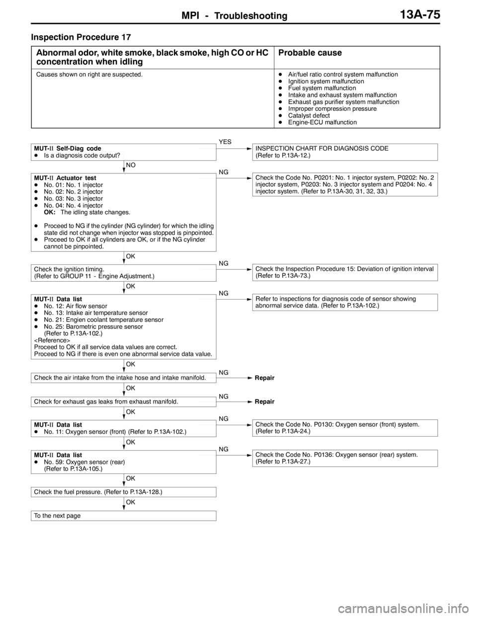
Inspection Procedure 17
Abnormal odor, white smoke, black smoke, high CO or HC
concentration when idling
Probable cause
Causes shown on right are suspected.DAir/fuel ratio control system malfunction
DIgnition system malfunction
DFuel system malfunction
DIntake and exhaust system malfunction
DExhaust gas purifier system malfunction
DImproper compression pressure
DCatalyst defect
DEngine-ECU malfunction
OK
To the next page
OK
Check the fuel pressure. (Refer to P.13A-128.)
OK
MUT-IIData list
DNo. 59: Oxygen sensor (rear)
(Refer to P.13A-105.)NGCheck the Code No. P0136: Oxygen sensor (rear) system.
(Refer to P.13A-27.)
OK
MUT-IIData list
DNo. 11: Oxygen sensor (front) (Refer to P.13A-102.)NGCheck the Code No. P0130: Oxygen sensor (front) system.
(Refer to P.13A-24.)
OK
Check for exhaust gas leaks from exhaust manifold.NG
Repair
OK
Check the air intake from the intake hose and intake manifold.NG
Repair
OK
MUT-IIData list
DNo. 12: Air flow sensor
DNo. 13: Intake air temperature sensor
DNo. 21: Engien coolant temperature sensor
DNo. 25: Barometric pressure sensor
(Refer to P.13A-102.)
Proceed to OK if all service data values are correct.
Proceed to NG if there is even one abnormal service data value.NGRefer to inspections for diagnosis code of sensor showing
abnormal service data. (Refer to P.13A-102.)
OK
Check the ignition timing.
(Refer to GROUP 11 - Engine Adjustment.)NGCheck the Inspection Procedure 15: Deviation of ignition interval
(Refer to P.13A-73.)
NO
MUT-IIActuator test
DNo. 01: No. 1 injector
DNo. 02: No. 2 injector
DNo. 03: No. 3 injector
DNo. 04: No. 4 injector
OK:The idling state changes.
DProceed to NG if the cylinder (NG cylinder) for which the idling
state did not change when injector was stopped is pinpointed.
DProceed to OK if all cylinders are OK, or if the NG cylinder
cannot be pinpointed.NGCheck the Code No. P0201: No. 1 injector system, P0202: No. 2
injector system, P0203: No. 3 injector system and P0204: No. 4
injector system. (Refer to P.13A-30, 31, 32, 33.)
MUT-IISelf-Diag code
DIs a diagnosis code output?YESINSPECTION CHART FOR DIAGNOSIS CODE
(Refer to P.13A-12.)
Page 611 of 1449

MPI -Troubleshooting13A-79
Inspection Procedure 19
Overheating
Probable cause
Causes shown on right are suspected.DEngine coolant insufficient or deteriorated
DFan controller malfunction
DEngine coolant temperature sensor malfunction
DThermostat malfunction
DWater pump malfunction
DCondenser fan relay malfunction
DRadiator core malfunction
DEngine-ECU malfunction
NO
NG
Replace or replenish the engine coolant.
OK
Replace the radiator core.
OK
Check the water pump. (Refer to GROUP 14 - Water pump.)NGReplace the water pump.
OK
Check the thermostat. (Refer to GROUP 14 - Thermostat.)NGReplace the thermostat.
OK
MUT-IIData list
DNo. 21: Engine coolant temperaure sensor
OK:Approximately the same as the ambient temperature
when cooled.
Between 80 - 120_C when hot.NGCheck the Code No. P0115: Engine coolant temperature
sensor system. (Refer to P.13A-19.)
MUT-IIData list
21 Engine coolant temperature sensor (Refer to P.13A-102.)
OK
MUT-IIActuator Test
DNo. 37: Condenser fan (HI)
DNo. 38: Condenser fan (LOW)
DIgnition switch: ON
OK:Condenser fan rotates (low speed).
OK:Condenser fan rotates (high speed).NGCheck the Inspection Procedure 25: Condenser fan control
relay system. (Refer to P.13A-89.)
MUT-IIActuator Test
DNo. 21: Fan controller
DIgnition switch: ON
OK:Radiator fan rotates.NGCheck the Inspection Procedure 24: Radiator fan control relay
system. (Refer to P.13A-87.)
OK
Check the engine coolant.
(Refer to GROUP 14 - On-vehicle Service.)
If the engine coolant level is low, check whether the engine
coolant has leaked, and repair if required.
MUT-IISelf-Diag Code
Is a diagnosis code output?YESINSPECTION CHART FOR DIAGNOSIS CODE (Refer to
P.13A-12.)
Page 614 of 1449

MPI -Troubleshooting13A-82
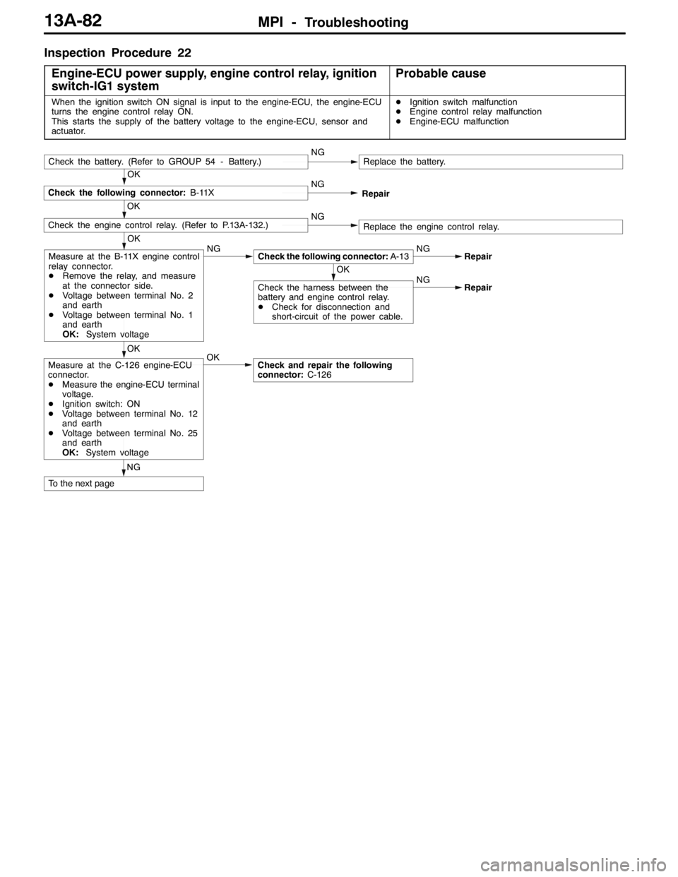
Inspection Procedure 22
Engine-ECU power supply, engine control relay, ignition
switch-IG1 system
Probable cause
When the ignition switch ON signal is input to the engine-ECU, the engine-ECU
turns the engine control relay ON.
This starts the supply of the battery voltage to the engine-ECU, sensor and
actuator.DIgnition switch malfunction
DEngine control relay malfunction
DEngine-ECU malfunction
OK
Check the engine control relay. (Refer to P.13A-132.)NGReplace the engine control relay.
OK
Check the following connector:B-11XNG
Check the battery. (Refer to GROUP 54 - Battery.)NGReplace the battery.
Repair
OK
OK
Measure at the B-11X engine control
relay connector.
DRemove the relay, and measure
at the connector side.
DVoltage between terminal No. 2
and earth
DVoltage between terminal No. 1
and earth
OK:System voltageNGCheck the following connector:A-13NG
OK
Check the harness between the
battery and engine control relay.
DCheck for disconnection and
short-circuit of the power cable.NGRepair
Repair
NGOK
Check and repair the following
connector:C-126Measure at the C-126 engine-ECU
connector.
DMeasure the engine-ECU terminal
voltage.
DIgnition switch: ON
DVoltage between terminal No. 12
and earth
DVoltage between terminal No. 25
and earth
OK:System voltage
To the next page
Page 627 of 1449

MPI -Troubleshooting13A-95
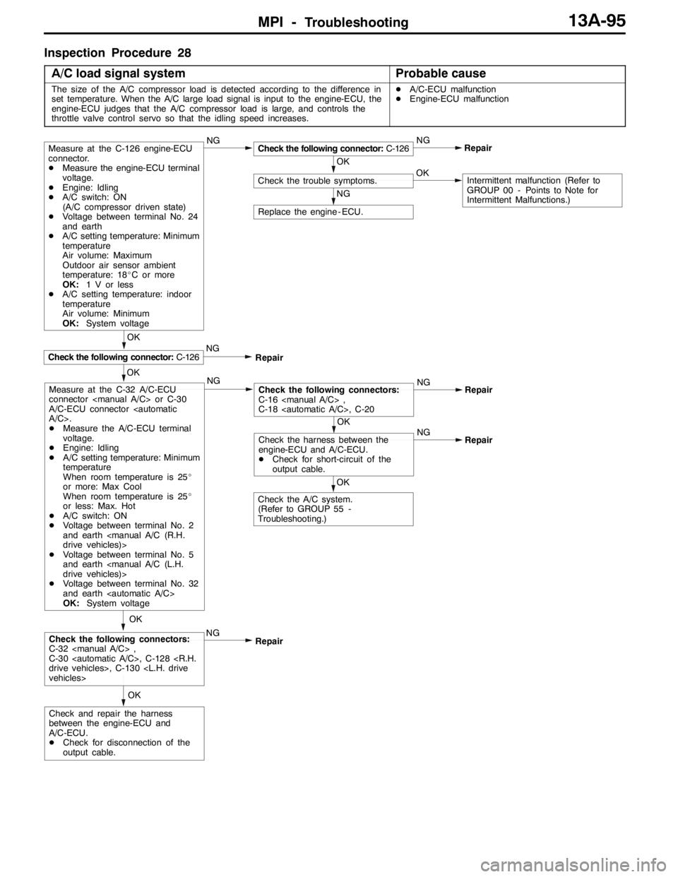
Inspection Procedure 28
A/C load signal system
Probable cause
The size of the A/C compressor load is detected according to the difference in
set temperature. When the A/C large load signal is input to the engine-ECU, the
engine-ECU judges that the A/C compressor load is large, and controls the
throttle valve control servo so that the idling speed increases.DA/C-ECU malfunction
DEngine-ECU malfunction
OK
NG
OK
NG
Check the trouble symptoms.NG
Check the following connector:C-126Repair
OK
Check the following connector:C-126
Replace the engine - ECU.
Measure at the C-126 engine-ECU
connector.
DMeasure the engine-ECU terminal
voltage.
DEngine: Idling
DA/C switch: ON
(A/C compressor driven state)
DVoltage between terminal No. 24
and earth
DA/C setting temperature: Minimum
temperature
Air volume: Maximum
Outdoor air sensor ambient
temperature: 18_C or more
OK:1 V or less
DA/C setting temperature: indoor
temperature
Air volume: Minimum
OK:System voltage
NG
Repair
NGNG
Repair
OK
OK
Check the harness between the
engine-ECU and A/C-ECU.
DCheck for short-circuit of the
output cable.NG
Repair
Check the A/C system.
(Refer to GROUP 55 -
Troubleshooting.)OK
Intermittent malfunction (Refer to
GROUP 00 - Points to Note for
Intermittent Malfunctions.)
Check the following connectors:
C-16
C-18
NG
Repair OK
OK
Check and repair the harness
between the engine-ECU and
A/C-ECU.
DCheck for disconnection of the
output cable.
Check the following connectors:
C-32
C-30
Measure at the C-32 A/C-ECU
connector
A/C-ECU connector
DMeasure the A/C-ECU terminal
voltage.
DEngine: Idling
DA/C setting temperature: Minimum
temperature
When room temperature is 25_
or more: Max Cool
When room temperature is 25_
or less: Max. Hot
DA/C switch: ON
DVoltage between terminal No. 2
and earth
DVoltage between terminal No. 5
and earth
DVoltage between terminal No. 32
and earth
OK:System voltage
Page 634 of 1449
![MITSUBISHI LANCER EVOLUTION 2007 Service Repair Manual MPI -Troubleshooting13A-102
DATA LIST REFERENCE TABLE
NOTE
*1. In a new Vehicle [driven approximately 500 km or less], the air flow sensor output frequency time
is sometimes 10% longer than the standa MITSUBISHI LANCER EVOLUTION 2007 Service Repair Manual MPI -Troubleshooting13A-102
DATA LIST REFERENCE TABLE
NOTE
*1. In a new Vehicle [driven approximately 500 km or less], the air flow sensor output frequency time
is sometimes 10% longer than the standa](/img/19/57084/w960_57084-633.png)
MPI -Troubleshooting13A-102
DATA LIST REFERENCE TABLE
NOTE
*1. In a new Vehicle [driven approximately 500 km or less], the air flow sensor output frequency time
is sometimes 10% longer than the standard time.
*2. The injector drive time represents the time when the cranking speed is at 250 r/min or below when
the power supply voltage is 11 V.
*3. In a new vehicle [driven approximately 500 km or less], the injector drive time is sometimes 10%
longer than the standard time.
*4. In a new vehicle [driven approximately 500 km or less], the step of the stepper motor is sometimes
30 steps greater than the standard value.
Item
No.Inspection
itemInspection contentsNormal conditionInspection
procedure
No.Reference
page
11Oxygen
sensor
(front)Engine: After having
warmed up
(Air/fuel mixuture is
made leaner whenWhen at 4,000 r/min,
engine is suddenly de-
celerated200 mV or lessCode No.
P013013A-24
madeleanerwhen
decelerating, and is
made richer when rac-
ing.)When engine is sud-
denly raced600 - 1,000 mV
Engine: After having
warmed up
(The oxygen sensor
(front) signal is used
tochecktheair/fuel
Engine is idling400 mV or less↔
600 - 1,000 mV
(Varies)
to check the air/fuel
mixture ratio, and
control condition is
also checked by the
engine-ECU.)2,500 r/min
12Air flow
sensor*1DEngine coolant
temperature:
Idle operation17 - 43 Hz--
sensor*1temperature:
80 - 95_C
DLightningandall
2,500 r/min40 - 100 Hz
DLightning andall
accessories:
OFF
DTransmission:
NeutralAccelerationAccording to ac-
celeration, fre-
quency is ampli-
fied.
13Intake air
temperature
sensor
Ignition switch: “ON”
or engine runningWhen intake air temper-
ature is - 20_C-20_CCode No.
P011013A-13
sensorWhen intake air tem-
perature is 0_C0_C
When intake air tem-
perature is 20_C20_C
When intake air tem-
perature is 40_C40_C
When intake air tem-
perature is 80_C80_C
Page 635 of 1449

MPI -Troubleshooting13A-103
Item
No.Reference
page Inspection
procedure
No. Normal condition Inspection contents Inspection
item
14Throttle
position
Ignition switch: “ON”Set to idle position535 - 735 mVCode No.
P0120
13A-21
position
sensor
Gradually openIncreases in pro-
portion to throttle
opening angle
P0120
Open fully4,500 - 5,000 mV
16Battery
voltageIgnition switch: “ON”System voltageProcedure
No. 2213A-82
18Cranking
signalIgnition switch: “ON”Engine: StoppedOFFProcedure
No.2213A-82
signal
(ignition
switch-ST)Engine: CrankingON
No.22
21Engine
coolant
temperature
Ignition switch: “ON”
or engine runningWhen engine coolant
temperature is - 20_C-20_CCode No.
P011513A-19
temperature
sensorWhen engine coolant
temperature is 0_C0_C
When engine coolant
temperature is 20_C20_C
When engine coolant
temperature is 40_C40_C
When engine coolant
temperature is 80_C80_C
22Crank
angle
sensorDEngine: Cranking
DTachometer:
ConnectedCompare the engine
speed readings on the
tachometer and the
MUT-II.Accord--
DEngine: Idle
operationWhen engine coolant
temperature is - 20_C1,300 - 1,500
r/min
When engine coolant
temperature is 0_C1,300 - 1,500
r/min
When engine coolant
temperature is 20_C1,300 - 1,500
r/min
When engine coolant
temperature is 40_C1,150 - 1,350
r/min
When engine coolant
temperature is 80_C600 - 900 r/min
24LVehicle
speed
sensorDrive at 40 km/hApproximately 40
km/hCode No.
P050013A-43
Page 636 of 1449

MPI -Troubleshooting13A-104
Item
No.Reference
page Inspection
procedure
No. Normal condition Inspection contents Inspection
item
25Barometric
pressure
Ignition switch: ONAltitude: 0 m101 kPaCode No.
P0105
13A-15
pressure
sensor
Altitude: 0 m95 kPa
P0105
Altitude: 0 m88 kPa
Altitude: 0 m81 kPa
27Power
steering
fluidEngine: Idle operationSteering wheel
stationaryOFFCode No.
P055113A-46
fluid
pressure
switchSteering wheel turningON
28A/C switchEngine: Idle operation
(When A/C switch isA/C switch: OFFOFFProcedure
No. 2613A-92
(WhenA/Cswitchis
ON, A/C compressor
should be operating.)A/C switch: ONON
No.26
34Air flow
sensorEngine: After
warm-upIdle operationONCode No.
P010013A-13
sensor
reset
signal
warm up
3,000 r/minOFF
P0100
37Volumetric
efficiency
DEngine coolant
temperature:
Idle operation15 - 35%--
efficiencytemperature:
85 - 95_C
DLightningand
2,500 r/min15 - 35%
DLightning and
accessories:
OFFExcessive
accellerationAccording to ac-
celeration, volu-
metric efficiency
is increased.
41Injectors*1Engine: CrankingWhen engine coolant
temperature is 0_C
(injection is carried out
for all cylinders simulta-
neously)25 - 37 ms--
When engine coolant
temperature is 20_C15 - 22 ms
When engine coolant
temperature is 80_C4.2 - 6.3 ms
Injectors*2DEngine coolant
temperature:
80–95_C
Engine: Idle operation1.5 - 2.7 ms--
80–95_C
DLamps, electric
cooling fan and
allaccessories:
2,500 r/min1.2 - 2.4 ms
allaccessories:
OFF
DTransmission:
Neutral
When engine is sud-
denly racedIncreases
Page 637 of 1449

MPI -Troubleshooting13A-105
Item
No.Reference
page Inspection
procedure
No. Normal condition Inspection contents Inspection
item
44Ignition ad-
vanceDEngine: After
having warmed
up
DTiming lamp is
set(Thetiming
Engine: Idle operation0-13_BTDC--
set.(Thetiming
lamp is set in
order to check
actual ignition
timing.)
2,500 r/min20 - 40_BTDC
45Idle speed
control
(stepper)
motor
position*
3
DEngine coolant
temperature:
80 - 90_C
DLamps, electric
cooling fan and
all accessories:
OFF
DTransmission:
A/C switch: OFF2 - 25 STEP--
DTransmission:
Neutral
DEngine: Idle
operation
DWhen A/C switch
is ON, A/C
compressor
should be operat-
ing
A/C switch: OFF→ONIncreases by 10 -
70 steps
49A/C relayEngine: After having
warmed up/Engine is
idlingA/C switch: OFFOFF (Compressor
clutch is not oper-
ating)Procedure
No. 2713A-92
A/C switch: ONON (Compressor
clutch is operat-
ing)
59Oxygen
sensor
(rear)Engine: After having
warmed-upWhen engine is sud-
denly raced0 and 600 - 1,000
mV alternate.Code No.
P013613A-27
81LLearned
valueEngine: After having warmed up, running with no
load at 2,500 r/min. (During air/fuel ratio
feedback control)- 12.5 - 12.5%--
82LFeedbackEngine: After having warmed up, running with no
load at 2,500 r/min. (During air/fuel ratio
feedback control)- 20 - 20%--
87LEngine
load
Engine: After having
warmedup
Idle operation15 - 35%--
loadwarmedup
2,500 r/min15 - 35%--
Page 638 of 1449

MPI -Troubleshooting13A-106
Item
No.Reference
page Inspection
procedure
No. Normal condition Inspection contents Inspection
item
A1LOxygen
sensor
(front)Engine: After having
warmed up
(Air/fuel mixture is
made leaner whenWhen at 4,000 r/min,
engine is suddenly de-
celerated200 mV or lessCode No.
P013013A-24
madeleanerwhen
decelerating, and is
made richer when
racing.)When engine is sud-
denly raced600 - 1,000 mV
Engine: After having
warmed up
(By using oxygen
sensorcheckair/fuel
Idle operation400 mV or less↔
600 - 1,000 mV
(altered)
sensor, checkair/fuel
mixture as well as
control status by
engine-ECU)2,500 r/min
A2LOxygen
sensor
(rear)Engine: After having
warmed upWhen engine is sud-
denly raced0 and 600 - 1,000
mV alternate.Code No.
P013613A-27
8ALThrottle
position
sensor
DEngine: After
having warmed
up
Release the accelera-
tor pedal.8 - 16%Code No.
P012013A-21
sensor
(Throttle
position
opening
angle)up
DIgnition switch:
“ON” (Engine
stopped)Depress the accelera-
tor pedal gradually.Increase in re-
sponse to the
pedal depression
stroke.
Depress the accelera-
tor pedal fully.80 - 100%
NOTE
Items marked byLwill not displayed if service data is selected on the check mode.
Page 640 of 1449

MPI -Troubleshooting13A-108
Item
No.Reference
page Inspection
procedure
No. Normal condition Inspection contents Drive contents Inspection
item
21Fan
controllerRadiator fan
motor is
driven.Ignition switch: “ON”Fan motor rotates
at high speed.Procedure
No. 2413A-87
36Secondary
air control
solenoid
valveSolenoid valve
turns from
OFF to ON.Ignition switch: “ON”Sound of opera-
tion can be heard
when solenoid
valve is driven.Procedure
No. 2913A-96
37Condenser
fan (HI)Condensor
fan motor is
driven.Ignition switch: “ON”Fan motor rotates
at high speed.Procedure
No. 2513A-89
38Condenser
fan (LOW)Second air
control
solenoid valveIgnition switch: “ON”Fan motor rotates
at low speed.
CHECK AT THE ENGINE-ECU TERMINALS
TERMINAL VOLTAGE CHECK CHART
1. Connect a needle-nosed wire probe (test harness:
MB991223 or paper clip) to a voltmeter probe.
2. Insert the needle-nosed wire probe into each of the
engine-ECU connector terminals from the wire side, and
measure the voltage while referring to the check chart.
NOTE
(1) Make the voltage measurement with the engine-ECU
connectors connected.
(2) You may find it convenient to pull out the engine-ECU
to make it easier to reach the connector terminals.
(3) The checks can be carried out off the order given
in the chart.
Caution
Short-circuiting the positive (+) probe between a
connector terminal and earth could damage the
vehicle wiring, the sensor, engine-ECU or all of them.
Be careful to prevent this!
3. If voltmeter shows any division from standard value, check
the corresponding sensor, actuator and related electrical
wiring, then repair or replace.
4. After repair or replacement, recheck with the voltmeter
to confirm that the repair has corrected the problem.
Needle-nosed wire probe