sensor MITSUBISHI LANCER EVOLUTION 2007 Service Owners Manual
[x] Cancel search | Manufacturer: MITSUBISHI, Model Year: 2007, Model line: LANCER EVOLUTION, Model: MITSUBISHI LANCER EVOLUTION 2007Pages: 1449, PDF Size: 56.82 MB
Page 561 of 1449
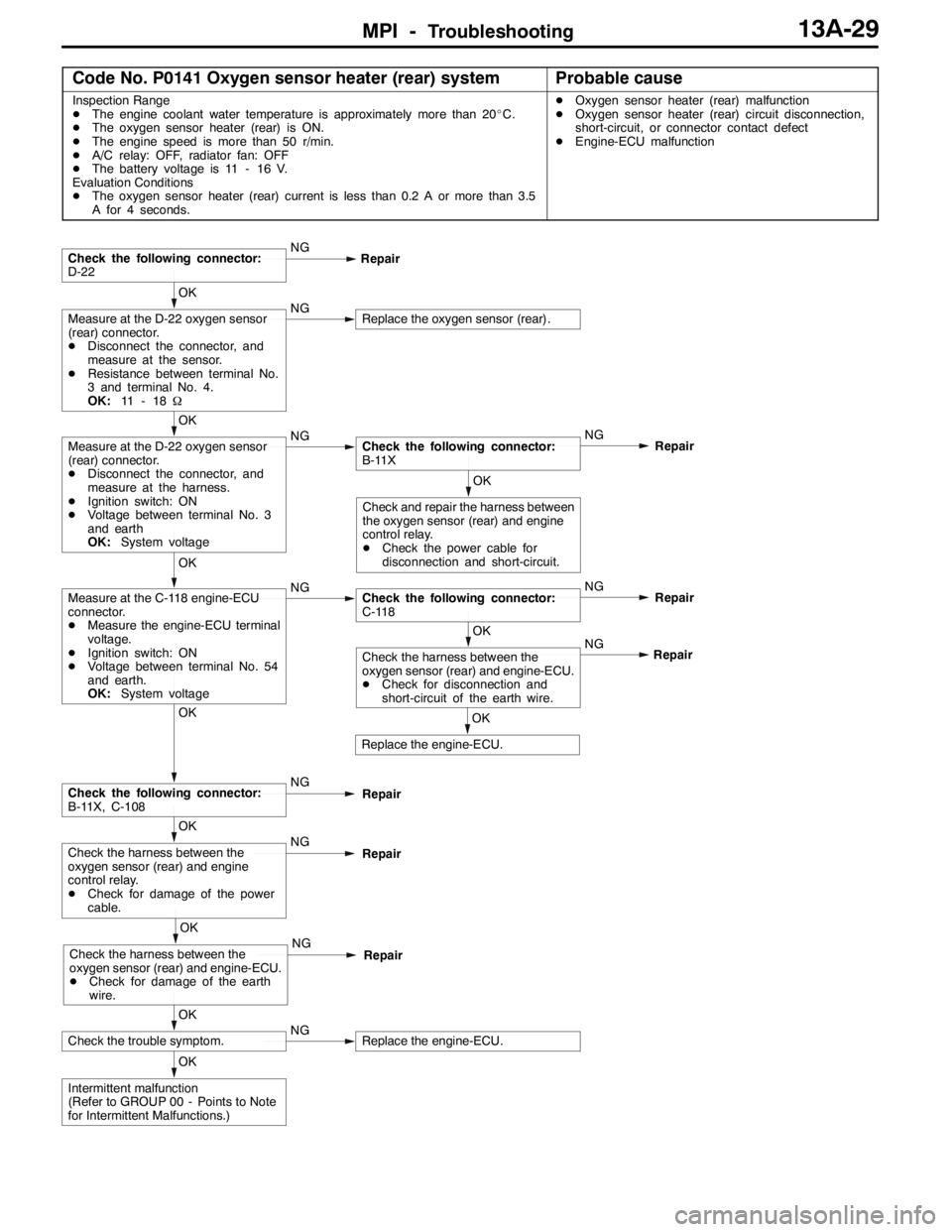
MPI -Troubleshooting13A-29
Code No. P0141 Oxygen sensor heater (rear) systemProbable cause
Inspection Range
DThe engine coolant water temperature is approximately more than 20_C.
DThe oxygen sensor heater (rear) is ON.
DThe engine speed is more than 50 r/min.
DA/C relay: OFF, radiator fan: OFF
DThe battery voltage is 11 - 16 V.
Evaluation Conditions
DThe oxygen sensor heater (rear) current is less than 0.2 A or more than 3.5
A for 4 seconds.DOxygen sensor heater (rear) malfunction
DOxygen sensor heater (rear) circuit disconnection,
short-circuit, or connector contact defect
DEngine-ECU malfunction
OK
Intermittent malfunction
(Refer to GROUP 00 - Points to Note
for Intermittent Malfunctions.)
OK
Check the trouble symptom.NGReplace the engine-ECU.
OK
Check the harness between the
oxygen sensor (rear) and engine-ECU.
DCheck for damage of the earth
wire.NG
Repair
OK
Check the harness between the
oxygen sensor (rear) and engine
control relay.
DCheck for damage of the power
cable.NG
Repair
OK
Check the following connector:
B-11X, C-108NG
Repair
OK
Replace the engine-ECU.NG
OK
Check the harness between the
oxygen sensor (rear) and engine-ECU.
DCheck for disconnection and
short-circuit of the earth wire.Repair
OK
Measure at the C-118 engine-ECU
connector.
DMeasure the engine-ECU terminal
voltage.
DIgnition switch: ON
DVoltage between terminal No. 54
and earth.
OK:System voltageNGCheck the following connector:
C-118NG
Repair
OK
Check and repair the harness between
the oxygen sensor (rear) and engine
control relay.
DCheck the power cable for
disconnection and short-circuit.
OK
Measure at the D-22 oxygen sensor
(rear) connector.
DDisconnect the connector, and
measure at the harness.
DIgnition switch: ON
DVoltage between terminal No. 3
and earth
OK:System voltageNGCheck the following connector:
B-11XNG
Repair
OK
Measure at the D-22 oxygen sensor
(rear) connector.
DDisconnect the connector, and
measure at the sensor.
DResistance between terminal No.
3 and terminal No. 4.
OK:11 - 1 8ΩNGReplace the oxygen sensor (rear).
Check the following connector:
D-22NG
Repair
Page 562 of 1449
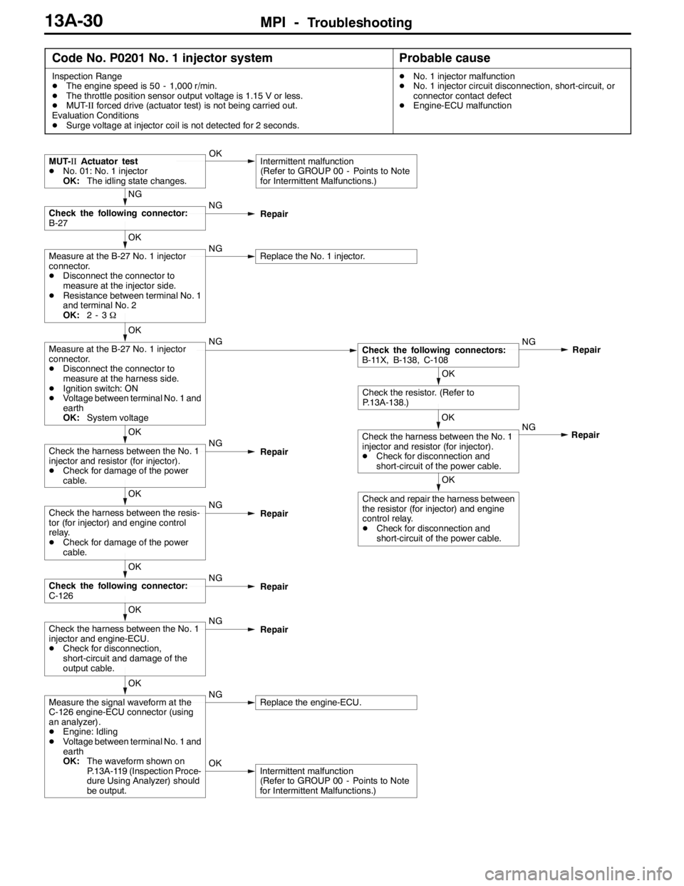
MPI -Troubleshooting13A-30
Code No. P0201 No. 1 injector systemProbable cause
Inspection Range
DThe engine speed is 50 - 1,000 r/min.
DThe throttle position sensor output voltage is 1.15 V or less.
DMUT-IIforced drive (actuator test) is not being carried out.
Evaluation Conditions
DSurge voltage at injector coil is not detected for 2 seconds.DNo. 1 injector malfunction
DNo. 1 injector circuit disconnection, short-circuit, or
connector contact defect
DEngine-ECU malfunction
OKIntermittent malfunction
(Refer to GROUP 00 - Points to Note
for Intermittent Malfunctions.)
OK
Measure the signal waveform at the
C-126 engine-ECU connector (using
an analyzer).
DEngine: Idling
DVoltage between terminal No. 1 and
earth
OK:The waveform shown on
P.13A-119 (Inspection Proce-
dure Using Analyzer) should
be output.NGReplace the engine-ECU.
OK
Check the harness between the No. 1
injector and engine-ECU.
DCheck for disconnection,
short-circuit and damage of the
output cable.NG
Repair
OK
Check the following connector:
C-126NG
Repair
OK
Check the harness between the resis-
tor (for injector) and engine control
relay.
DCheck for damage of the power
cable.NG
Repair
OK
Check the harness between the No. 1
injector and resistor (for injector).
DCheck for damage of the power
cable.NG
Repair
OK
Check and repair the harness between
the resistor (for injector) and engine
control relay.
DCheck for disconnection and
short-circuit of the power cable.NG
OK
Check the harness between the No. 1
injector and resistor (for injector).
DCheck for disconnection and
short-circuit of the power cable.Repair
OK
Check the resistor. (Refer to
P.13A-138.)
OK
Measure at the B-27 No. 1 injector
connector.
DDisconnect the connector to
measure at the harness side.
DIgnition switch: ON
DVoltage between terminal No. 1 and
earth
OK:System voltageNGCheck the following connectors:
B-11X, B-138, C-108NG
Repair
OK
Measure at the B-27 No. 1 injector
connector.
DDisconnect the connector to
measure at the injector side.
DResistance between terminal No. 1
and terminal No. 2
OK:2-3ΩNGReplace the No. 1 injector.
NG
Check the following connector:
B-27NG
Repair
MUT-IIActuator test
DNo. 01: No. 1 injector
OK:The idling state changes.OKIntermittent malfunction
(Refer to GROUP 00 - Points to Note
for Intermittent Malfunctions.)
Page 563 of 1449
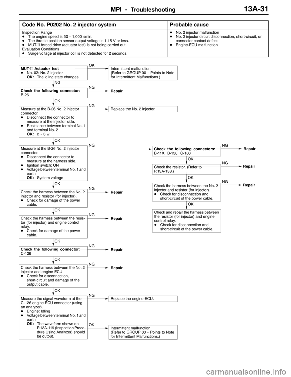
MPI -Troubleshooting13A-31
Code No. P0202 No. 2 injector systemProbable cause
Inspection Range
DThe engine speed is 50 - 1,000 r/min.
DThe throttle position sensor output voltage is 1.15 V or less.
DMUT-IIforced drive (actuator test) is not being carried out.
Evaluation Conditions
DSurge voltage at injector coil is not detected for 2 seconds.DNo. 2 injector malfunction
DNo. 2 injector circuit disconnection, short-circuit, or
connector contact defect
DEngine-ECU malfunction
OKIntermittent malfunction
(Refer to GROUP 00 - Points to Note
for Intermittent Malfunctions.)
OK
Measure the signal waveform at the
C-126 engine-ECU connector (using
an analyzer).
DEngine: Idling
DVoltage between terminal No. 1 and
earth
OK:The waveform shown on
P.13A-119 (Inspection Proce-
dure Using Analyzer) should
be output.NGReplace the engine-ECU.
OK
Check the harness between the No. 2
injector and engine-ECU.
DCheck for disconnection,
short-circuit and damage of the
output cable.NG
Repair
OK
Check the following connector:
C-126NG
Repair
OK
Check the harness between the resis-
tor (for injector) and engine control
relay.
DCheck for damage of the power
cable.NG
Repair
OK
Check and repair the harness between
the resistor (for injector) and engine
control relay.
DCheck for disconnection and
short-circuit of the power cable.NG
OK
Check the harness between the No. 2
injector and resistor (for injector).
DCheck for disconnection and
short-circuit of the power cable.Repair NG
OK
Check the resistor. (Refer to
P.13A-138.)Repair
OK
Check the harness between the No. 2
injector and resistor (for injector).
DCheck for damage of the power
cable.NG
Repair
OK
Measure at the B-26 No. 2 injector
connector.
DDisconnect the connector to
measure at the harness side.
DIgnition switch: ON
DVoltage between terminal No. 1 and
earth
OK:System voltageNGCheck the following connectors:
B-11X, B-138, C-108NG
Repair
OK
Measure at the B-26 No. 2 injector
connector.
DDisconnect the connector to
measure at the injector side.
DResistance between terminal No. 1
and terminal No. 2
OK:2-3ΩNGReplace the No. 2 injector.
NG
Check the following connector:
B-26NG
Repair
MUT-IIActuator test
DNo. 02: No. 2 injector
OK:The idling state changes.OKIntermittent malfunction
(Refer to GROUP 00 - Points to Note
for Intermittent Malfunctions.)
Page 564 of 1449
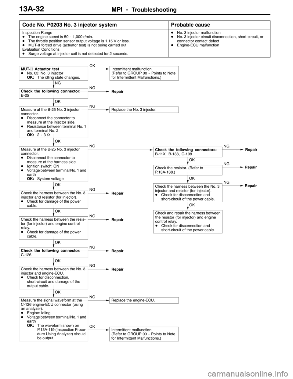
MPI -Troubleshooting13A-32
Code No. P0203 No. 3 injector systemProbable cause
Inspection Range
DThe engine speed is 50 - 1,000 r/min.
DThe throttle position sensor output voltage is 1.15 V or less.
DMUT-IIforced drive (actuator test) is not being carried out.
Evaluation Conditions
DSurge voltage at injector coil is not detected for 2 seconds.DNo. 3 injector malfunction
DNo. 3 injector circuit disconnection, short-circuit, or
connector contact defect
DEngine-ECU malfunction
OKIntermittent malfunction
(Refer to GROUP 00 - Points to Note
for Intermittent Malfunctions.)
OK
Measure the signal waveform at the
C-126 engine-ECU connector (using
an analyzer).
DEngine: Idling
DVoltage between terminal No. 1 and
earth
OK:The waveform shown on
P.13A-119 (Inspection Proce-
dure Using Analyzer) should
be output.NGReplace the engine-ECU.
OK
Check the harness between the No. 3
injector and engine-ECU.
DCheck for disconnection,
short-circuit and damage of the
output cable.NG
Repair
OK
Check the following connector:
C-126NG
Repair
OK
Check the harness between the resis-
tor (for injector) and engine control
relay.
DCheck for damage of the power
cable.NG
Repair
OK
Check and repair the harness between
the resistor (for injector) and engine
control relay.
DCheck for disconnection and
short-circuit of the power cable.NG
OK
Check the harness between the No. 3
injector and resistor (for injector).
DCheck for disconnection and
short-circuit of the power cable.Repair NG
OK
Check the resistor. (Refer to
P.13A-138.)Repair
OK
Check the harness between the No. 3
injector and resistor (for injector).
DCheck for damage of the power
cable.NG
Repair
OK
Measure at the B-25 No. 3 injector
connector.
DDisconnect the connector to
measure at the harness side.
DIgnition switch: ON
DVoltage between terminal No. 1 and
earth
OK:System voltageNGCheck the following connectors:
B-11X, B-138, C-108NG
Repair
OK
Measure at the B-25 No. 3 injector
connector.
DDisconnect the connector to
measure at the injector side.
DResistance between terminal No. 1
and terminal No. 2
OK:2-3ΩNGReplace the No. 3 injector.
NG
Check the following connector:
B-25NG
Repair
MUT-IIActuator test
DNo. 03: No. 3 injector
OK:The idling state changes.OKIntermittent malfunction
(Refer to GROUP 00 - Points to Note
for Intermittent Malfunctions.)
Page 565 of 1449
MPI -Troubleshooting13A-33
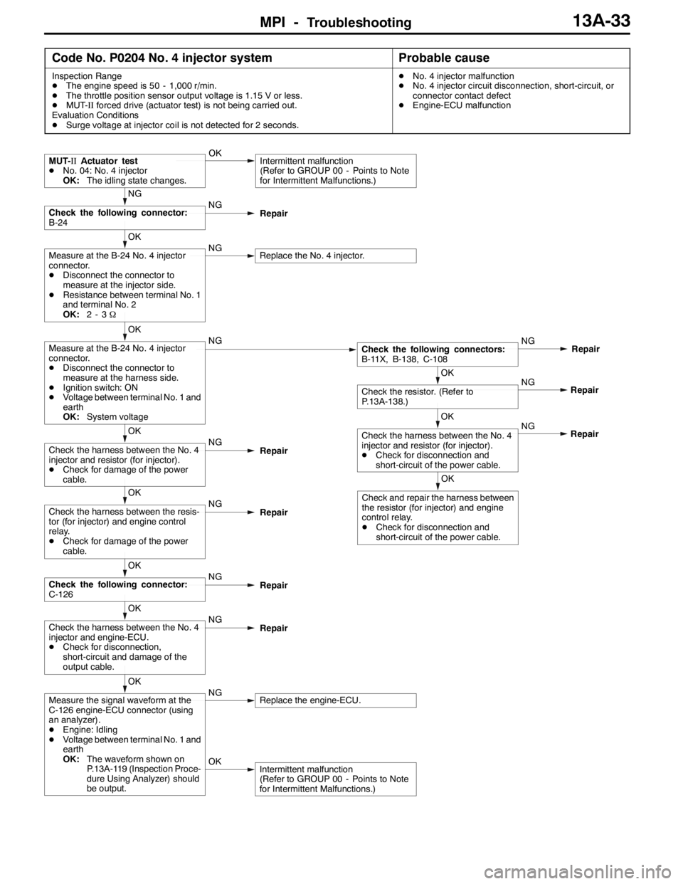
Code No. P0204 No. 4 injector systemProbable cause
Inspection Range
DThe engine speed is 50 - 1,000 r/min.
DThe throttle position sensor output voltage is 1.15 V or less.
DMUT-IIforced drive (actuator test) is not being carried out.
Evaluation Conditions
DSurge voltage at injector coil is not detected for 2 seconds.DNo. 4 injector malfunction
DNo. 4 injector circuit disconnection, short-circuit, or
connector contact defect
DEngine-ECU malfunction
OKIntermittent malfunction
(Refer to GROUP 00 - Points to Note
for Intermittent Malfunctions.)
OK
Measure the signal waveform at the
C-126 engine-ECU connector (using
an analyzer).
DEngine: Idling
DVoltage between terminal No. 1 and
earth
OK:The waveform shown on
P.13A-119 (Inspection Proce-
dure Using Analyzer) should
be output.NGReplace the engine-ECU.
OK
Check the harness between the No. 4
injector and engine-ECU.
DCheck for disconnection,
short-circuit and damage of the
output cable.NG
Repair
OK
Check the following connector:
C-126NG
Repair
OK
Check the harness between the resis-
tor (for injector) and engine control
relay.
DCheck for damage of the power
cable.NG
Repair
OK
Check and repair the harness between
the resistor (for injector) and engine
control relay.
DCheck for disconnection and
short-circuit of the power cable.NG
OK
Check the harness between the No. 4
injector and resistor (for injector).
DCheck for disconnection and
short-circuit of the power cable.Repair NG
OK
Check the resistor. (Refer to
P.13A-138.)Repair
OK
Check the harness between the No. 4
injector and resistor (for injector).
DCheck for damage of the power
cable.NG
Repair
OK
Measure at the B-24 No. 4 injector
connector.
DDisconnect the connector to
measure at the harness side.
DIgnition switch: ON
DVoltage between terminal No. 1 and
earth
OK:System voltageNGCheck the following connectors:
B-11X, B-138, C-108NG
Repair
OK
Measure at the B-24 No. 4 injector
connector.
DDisconnect the connector to
measure at the injector side.
DResistance between terminal No. 1
and terminal No. 2
OK:2-3ΩNGReplace the No. 4 injector.
NG
Check the following connector:
B-24NG
Repair
MUT-IIActuator test
DNo. 04: No. 4 injector
OK:The idling state changes.OKIntermittent malfunction
(Refer to GROUP 00 - Points to Note
for Intermittent Malfunctions.)
Page 566 of 1449
MPI -Troubleshooting13A-34
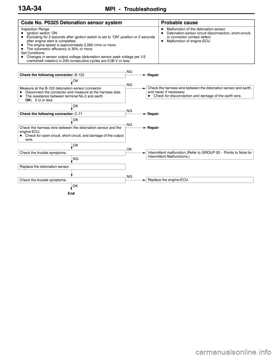
Code No. P0325 Detonation sensor systemProbable cause
Inspection Range
DIgnition switch: ON
DExcluding for 2 seconds after ignition switch is set to “ON” position or 2 seconds
after engine start is completed.
DThe engine speed is approximately 2,000 r/min or more.
DThe volumetric efficiency is 30% or more.
Set Conditions
DChanges in sensor output voltage (detonation sensor peak voltage per 1/2
crankshaft rotation) in 200 consecutive cycles are 0.06 V or less.DMalfunction of the detonation sensor
DDetonation sensor circuit disconnection, short-circuit,
or connector contact defect
DMalfunction of engine-ECU
OK
Check the trouble symptoms.NGReplace the engine-ECU.
NG
Replace the detonation sensor.
OK
Check the trouble symptoms.OKIntermittent malfunction (Refer to GROUP 00 - Points to Note for
Intermittent Malfunctions.)
OK
Check the harness wire between the detonation sensor and the
engine-ECU.
DCheck for open circuit, short circuit, and damage of the output
wire.NG
Repair
OK
Check the following connector:C-71NG
Repair
OK
Measure at the B-122 detonation sensor connector
DDisconnect the connector and measure at the harness side.
DThe resistance between terminal No.2 and earth
OK:2Ωor lessNGCheck the harness wire between the detonation sensor and earth,
and repair if necessary.
DCheck for disconnection and damage of the earth wire.
Check the following connector:B-122NG
Repair
End
Page 567 of 1449

MPI -Troubleshooting13A-35
Code No. P0335 Crank angle sensor systemProbable cause
Inspection Range
DEngine: During cranking
Evaluation Conditions
DThe sensor output voltage does not change for 2 seconds (no pulse signal output)DMalfunction of crank angle sensor
DOpen or short circuit in the crank angle sensor circuit
or loose connector contact
DMalfunction of engine-ECU
OK
To the next page
(3) NGCheck the harness between the crank
angle sensor and body earth, and
repair if necessary.
DCheck for open circuit and damage
of the earth wire.
OK
Check the harness between the crank
angle sensor and engine control relay,
repair if necessary.
DCheck for open circuit and short
circuit of the power cable.
(2) NGCheck the following connector:
B-11XNG
Repair
OK
Intermittent Malfunction
(Refer to GROUP 00 - Points to Note
for Intermittent Malfunction.)
OK
MUT-IIData list
DNo. 22 Crank angle sensor
(Refer to P.13A-103.)NGReplace the engine-ECU. NG
OK
Check the harness between the crank
angle sensor and engine-ECU.
DCheck for short circuit of the output
wire.Repair
OK
Check the harness between the crank
angle sensor and engine-ECU, and
repair if necessary.
DCheck for open circuit of the output
wire.NG
Repair
NG
NG
Check the following connector:
C-115Repair
OK
Measure at the B-121 crank angle
sensor connector.
DDisconnect the connector to
measure at the harness side
(1) Voltage between terminal No. 2 and
earth.
(Ignition switch: ON)
OK:4.9 - 5.1 V
(2) Voltage between terminal No. 3 and
earth.
(Ignition switch: ON)
OK:System voltage
(3) Resistance between terminal No. 1
and earth.
OK:Less than 2Ω(1) NGMeasure at the C-115 engine-ECU
connector.
DMeasure the engine-ECU terminal
voltage.
DDisconnect the crank angle sensor
connector B-121.
DIgnition switch: ON
DVoltage between terminal No. 89
and earth.
OK:4.9 - 5.1 VOKCheck the following connector:
C-115
NG
Check the following connector:
B-121NG
Repair
MUT-IIData list
DNo. 22 Crank angle sensor
(Refer to P.13A-103.)OKIntermittent Malfunction
(Refer to GROUP 00 - Points to Note
for Intermittent Malfunction.)
Page 568 of 1449
MPI -Troubleshooting13A-36
OK
Intermittent Malfunction
(Refer to GROUP 00 - Points to Note
for Intermittent Malfunction.)
OK
MUT-IIData list
DNo. 22 Crank angle sensor
(Refer to P.13A-103.)NGReplace the engine-ECU.
OK
Intermittent Malfunction
(Refer to GROUP 00 - Points to Note
for Intermittent Malfunction.)
OK
Check the trouble symptos.NGReplace the crank angle sensor.
OK
Check for crank angle sensor vane.NGReplace the crank angle sensor vane. NG
OK
Check the harness between the crank
angle sensor and body earth.
DCheck for damage of the earth
wire.Repair NG
OK
Check the harness between the crank
angle sensor and engine-ECU.
DCheck for damage of the output
wire.Reapir NG
OK
Check the following connector:
C-115Repair NG
OK
Check the harness between the crank
angle sensor and engine control relay.
DCheck for damage of the power
cable.Repair
OK
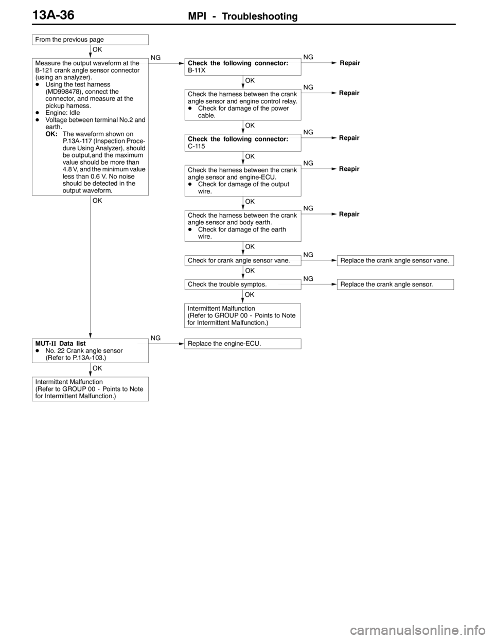
Measure the output waveform at the
B-121 crank angle sensor connector
(using an analyzer).
DUsing the test harness
(MD998478), connect the
connector, and measure at the
pickup harness.
DEngine: Idle
DVoltage between terminal No.2 and
earth.
OK:The waveform shown on
P.13A-117 (Inspection Proce-
dure Using Analyzer), should
be output,and the maximum
value should be more than
4.8 V, and the minimum value
less than 0.6 V. No noise
should be detected in the
output waveform.NGCheck the following connector:
B-11XNG
Repair
From the previous page
Page 569 of 1449
MPI -Troubleshooting13A-37
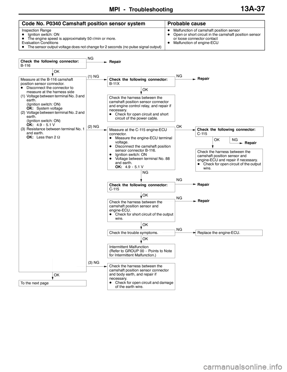
Code No. P0340 Camshaft position sensor systemProbable cause
Inspection Range
DIgnition switch: ON
DThe engine speed is approximately 50 r/min or more.
Evaluation Conditions
DThe sensor output voltage does not change for 2 seconds (no pulse signal output)DMalfunction of camshaft position sensor
DOpen or short circuit in the camshaft position sensor
or loose connector contact
DMalfunction of engine-ECU
OK
To the next page
(3) NGCheck the harness between the
camshaft position sensor connector
and body earth, and repair if
necessary.
DCheck for open circuit and damage
of the earth wire.
OK
Intermittent Malfunction
(Refer to GROUP 00 - Points to Note
for Intermittent Malfunction.)
OK
Check the trouble symptoms.NGReplace the engine-ECU.
OK
Check the harness between the
camshaft position sensor and
engine-ECU.
DCheck for short circuit of the output
wire.NG
Repair
NG
Check the following connector:
C-115NG
Repair
OK
Check the harness between the
camshaft position sensor and
engine-ECU and repair if necessary.
DCheck for open circuit of the output
wire.NG
Repair
(2) NGMeasure at the C-115 engine-ECU
connector.
DMeasure the engine-ECU terminal
voltage.
DDisconnect the camshaft position
sensor connector B-116.
DIgnition switch: ON
DVoltage between terminal No. 88
and earth.
OK:4.9 - 5.1 VOKCheck the following connector:
C-115
OK
Check the harness between the
camshaft position sensor connector
and engine control relay, and repair if
necessary.
DCheck for open circuit and short
circuit of the power cable.
OK
Measure at the B-116 camshaft
position sensor connector.
DDisconnect the connector to
measure at the harness side
(1) Voltage between terminal No. 3 and
earth.
(Ignition switch: ON)
OK:System voltage
(2) Voltage between terminal No. 2 and
earth.
(Ignition switch: ON)
OK:4.9 - 5.1 V
(3) Resistance between terminal No. 1
and earth.
OK:Less than 2Ω(1) NGCheck the following connector:
B-11XNG
Repair
Check the following connector:
B-116NG
Repair
Page 570 of 1449
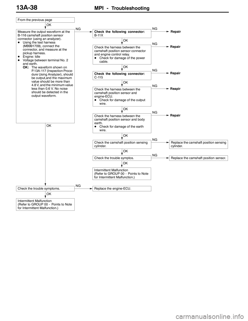
MPI -Troubleshooting13A-38
OK
Intermittent Malfunction
(Refer to GROUP 00 - Points to Note
for Intermittent Malfunction.)
OK
Check the trouble symptoms.NGReplace the engine-ECU.
OK
Intermittent Malfunction
(Refer to GROUP 00 - Points to Note
for Intermittent Malfunction.)
OK
Check the trouble symptos.NGReplace the camshaft position sensor.
OK
Check the camshaft position sensing
cylinder.NGReplace the camshaft position sensing
cylinder. NG
OK
Check the harness between the
camshaft position sensor and body
earth.
DCheck for damage of the earth
wire.Repair NG
OK
Check the harness between the
camshaft position sensor and
engine-ECU.
DCheck for damage of the output
wire.Reapir NG
OK
Check the following connector:
C-115Repair NG
OK
Check the harness between the
camshaft position sensor connector
and engine control relay.
DCheck for damage of the power
cable.Repair
OK
Measure the output waveform at the
B-116 camshaft position sensor
connector (using an analyzer).
DUsing the test harness
(MB991709), connect the
connector, and measure at the
pickup harness.
DEngine: Idle
DVoltage between terminal No. 2
and earth.
OK:The waveform shown on
P.13A-117 (Inspection Proce-
dure Using Analyzer), should
be output,and the maximum
value should be more than
4.8 V, and the minimum value
less than 0.6 V. No noise
should be detected in the
output waveform.NGCheck the following connector:
B-11XNG
Repair
From the previous page