sensor MITSUBISHI LANCER EVOLUTION 2007 Service Repair Manual
[x] Cancel search | Manufacturer: MITSUBISHI, Model Year: 2007, Model line: LANCER EVOLUTION, Model: MITSUBISHI LANCER EVOLUTION 2007Pages: 1449, PDF Size: 56.82 MB
Page 575 of 1449
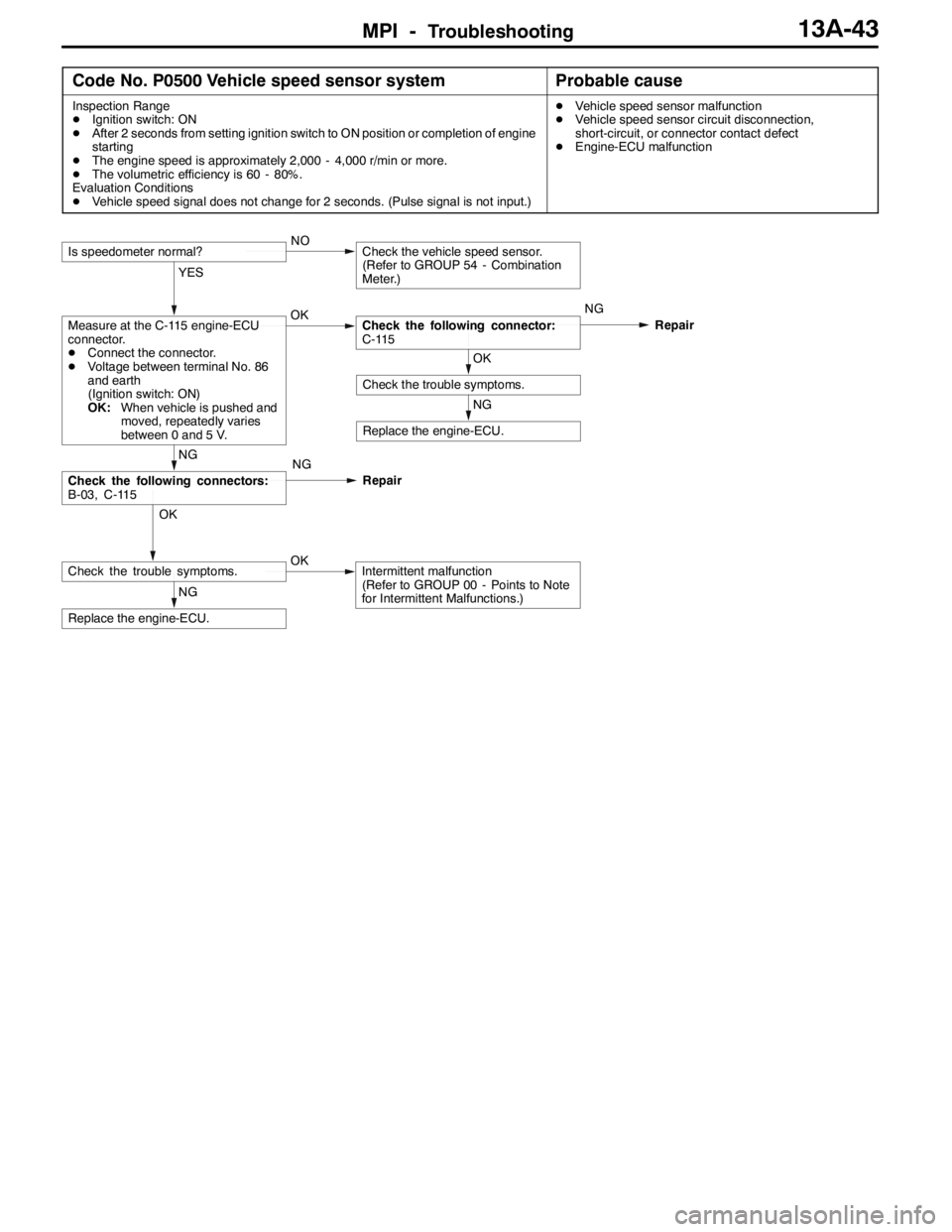
MPI -Troubleshooting13A-43
Code No. P0500 Vehicle speed sensor systemProbable cause
Inspection Range
DIgnition switch: ON
DAfter 2 seconds from setting ignition switch to ON position or completion of engine
starting
DThe engine speed is approximately 2,000 - 4,000 r/min or more.
DThe volumetric efficiency is 60 - 80%.
Evaluation Conditions
DVehicle speed signal does not change for 2 seconds. (Pulse signal is not input.)DVehicle speed sensor malfunction
DVehicle speed sensor circuit disconnection,
short-circuit, or connector contact defect
DEngine-ECU malfunction
NG
Replace the engine-ECU.
OK
Check the trouble symptoms.OKIntermittent malfunction
(Refer to GROUP 00 - Points to Note
for Intermittent Malfunctions.)
NG
Check the following connectors:
B-03, C-115
NG
Replace the engine-ECU.
OK
Check the trouble symptoms.
YES
Measure at the C-115 engine-ECU
connector.
DConnect the connector.
DVoltage between terminal No. 86
and earth
(Ignition switch: ON)
OK:When vehicle is pushed and
moved, repeatedly varies
between 0 and 5 V.OKCheck the following connector:
C-115NG
Repair
Is speedometer normal?NOCheck the vehicle speed sensor.
(Refer to GROUP 54 - Combination
Meter.)
NG
Repair
Page 591 of 1449
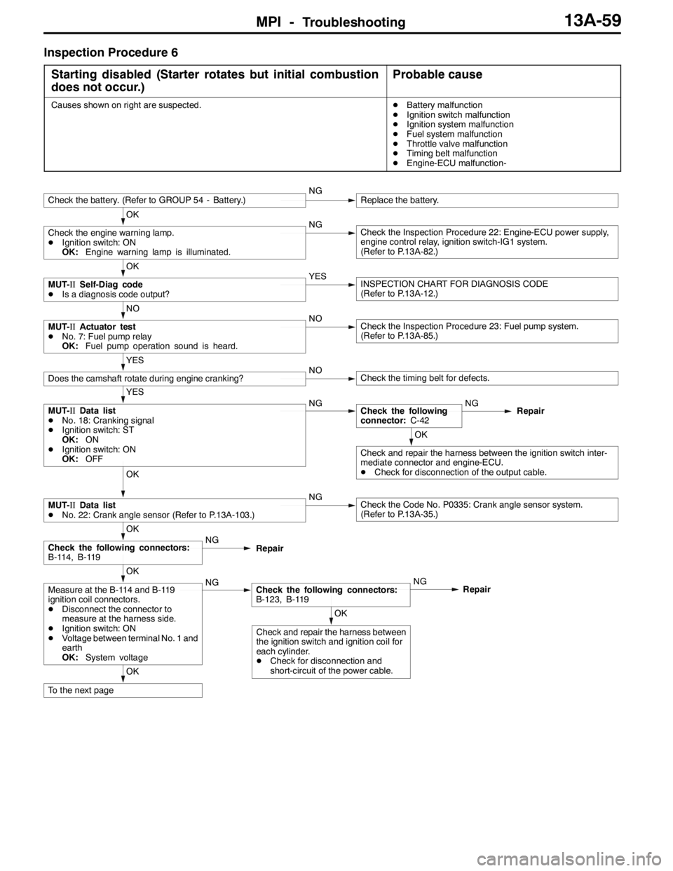
MPI -Troubleshooting13A-59
Inspection Procedure 6
Starting disabled (Starter rotates but initial combustion
does not occur.)
Probable cause
Causes shown on right are suspected.DBattery malfunction
DIgnition switch malfunction
DIgnition system malfunction
DFuel system malfunction
DThrottle valve malfunction
DTiming belt malfunction
DEngine-ECU malfunction-
OK
To the next page
OK
Check and repair the harness between
the ignition switch and ignition coil for
each cylinder.
DCheck for disconnection and
short-circuit of the power cable.
OK
Measure at the B-114 and B-119
ignition coil connectors.
DDisconnect the connector to
measure at the harness side.
DIgnition switch: ON
DVoltage between terminal No. 1 and
earth
OK:System voltageNGCheck the following connectors:
B-123, B-119NG
Repair
OK
Check the following connectors:
B-114, B-119NG
Repair
OK
MUT-IIData list
DNo. 22: Crank angle sensor (Refer to P.13A-103.)NGCheck the Code No. P0335: Crank angle sensor system.
(Refer to P.13A-35.)
OK
Check and repair the harness between the ignition switch inter-
mediate connector and engine-ECU.
DCheck for disconnection of the output cable.
YES
MUT-IIData list
DNo. 18: Cranking signal
DIgnition switch: ST
OK:ON
DIgnition switch: ON
OK:OFFNGCheck the following
connector:C-42NG
Repair
YES
Does the camshaft rotate during engine cranking?NOCheck the timing belt for defects.
NO
MUT-IIActuator test
DNo. 7: Fuel pump relay
OK:Fuel pump operation sound is heard.NOCheck the Inspection Procedure 23: Fuel pump system.
(Refer to P.13A-85.)
OK
MUT-IISelf-Diag code
DIs a diagnosis code output?YESINSPECTION CHART FOR DIAGNOSIS CODE
(Refer to P.13A-12.)
OK
Check the engine warning lamp.
DIgnition switch: ON
OK:Engine warning lamp is illuminated.NGCheck the Inspection Procedure 22: Engine-ECU power supply,
engine control relay, ignition switch-IG1 system.
(Refer to P.13A-82.)
Check the battery. (Refer to GROUP 54 - Battery.)NGReplace the battery.
Page 593 of 1449
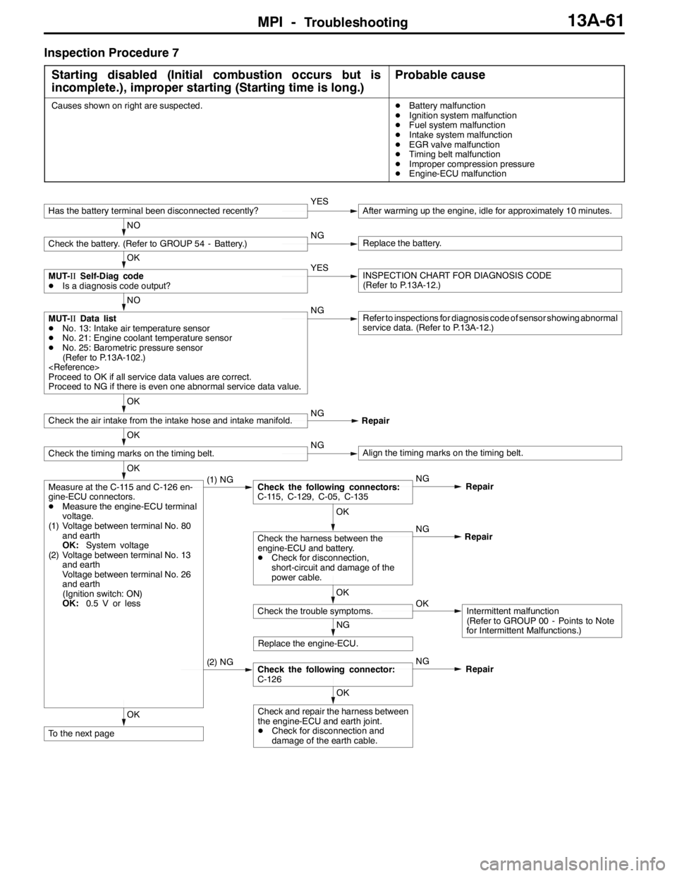
MPI -Troubleshooting13A-61
Inspection Procedure 7
Starting disabled (Initial combustion occurs but is
incomplete.), improper starting (Starting time is long.)
Probable cause
Causes shown on right are suspected.DBattery malfunction
DIgnition system malfunction
DFuel system malfunction
DIntake system malfunction
DEGR valve malfunction
DTiming belt malfunction
DImproper compression pressure
DEngine-ECU malfunction
OK
To the next page
OK
Check and repair the harness between
the engine-ECU and earth joint.
DCheck for disconnection and
damage of the earth cable.
(2) NGCheck the following connector:
C-126NG
Repair
NG
Replace the engine-ECU.
OK
Check the trouble symptoms.OKIntermittent malfunction
(Refer to GROUP 00 - Points to Note
for Intermittent Malfunctions.) NG
OK
Check the harness between the
engine-ECU and battery.
DCheck for disconnection,
short-circuit and damage of the
power cable.Repair
OK
Measure at the C-115 and C-126 en-
gine-ECU connectors.
DMeasure the engine-ECU terminal
voltage.
(1) Voltage between terminal No. 80
and earth
OK:System voltage
(2) Voltage between terminal No. 13
and earth
Voltage between terminal No. 26
and earth
(Ignition switch: ON)
OK:0.5 V or less(1) NGCheck the following connectors:
C-115, C-129, C-05, C-135NG
Repair
OK
Check the timing marks on the timing belt.NGAlign the timing marks on the timing belt.
OK
Check the air intake from the intake hose and intake manifold.NG
Repair
NO
MUT-IIData list
DNo. 13: Intake air temperature sensor
DNo. 21: Engine coolant temperature sensor
DNo. 25: Barometric pressure sensor
(Refer to P.13A-102.)
Proceed to OK if all service data values are correct.
Proceed to NG if there is even one abnormal service data value.NGRefer to inspections for diagnosis code of sensor showing abnormal
service data. (Refer to P.13A-12.)
OK
MUT-IISelf-Diag code
DIs a diagnosis code output?YESINSPECTION CHART FOR DIAGNOSIS CODE
(Refer to P.13A-12.)
NO
Check the battery. (Refer to GROUP 54 - Battery.)NGReplace the battery.
Has the battery terminal been disconnected recently?YESAfter warming up the engine, idle for approximately 10 minutes.
Page 595 of 1449
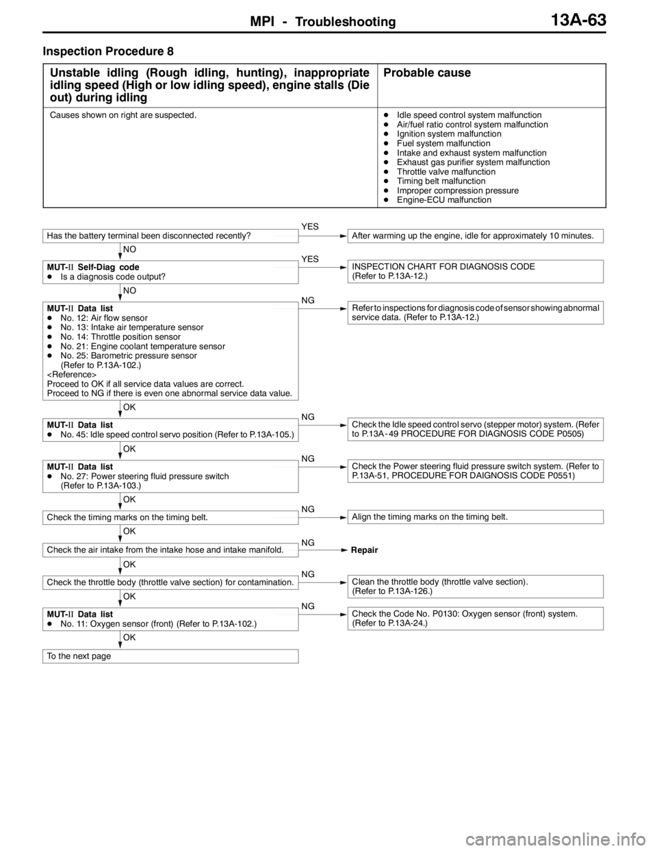
MPI -Troubleshooting13A-63
Inspection Procedure 8
Unstable idling (Rough idling, hunting), inappropriate
idling speed (High or low idling speed), engine stalls (Die
out) during idling
Probable cause
Causes shown on right are suspected.DIdle speed control system malfunction
DAir/fuel ratio control system malfunction
DIgnition system malfunction
DFuel system malfunction
DIntake and exhaust system malfunction
DExhaust gas purifier system malfunction
DThrottle valve malfunction
DTiming belt malfunction
DImproper compression pressure
DEngine-ECU malfunction
OK
To the next page
OK
MUT-IIData list
DNo. 11: Oxygen sensor (front) (Refer to P.13A-102.)NGCheck the Code No. P0130: Oxygen sensor (front) system.
(Refer to P.13A-24.)
OK
Check the throttle body (throttle valve section) for contamination.NGClean the throttle body (throttle valve section).
(Refer to P.13A-126.)
OK
Check the air intake from the intake hose and intake manifold.NG
Repair
OK
Check the timing marks on the timing belt.NGAlign the timing marks on the timing belt.
OK
MUT-IIData list
DNo. 27: Power steering fluid pressure switch
(Refer to P.13A-103.)NGCheck the Power steering fluid pressure switch system. (Refer to
P.13A-51, PROCEDURE FOR DAIGNOSIS CODE P0551)
OK
MUT-IIData list
DNo. 45: Idle speed control servo position (Refer to P.13A-105.)NGCheck the Idle speed control servo (stepper motor) system. (Refer
to P.13A - 49 PROCEDURE FOR DIAGNOSIS CODE P0505)
NO
MUT-IIData list
DNo. 12: Air flow sensor
DNo. 13: Intake air temperature sensor
DNo. 14: Throttle position sensor
DNo. 21: Engine coolant temperature sensor
DNo. 25: Barometric pressure sensor
(Refer to P.13A-102.)
Proceed to OK if all service data values are correct.
Proceed to NG if there is even one abnormal service data value.NGRefer to inspections for diagnosis code of sensor showing abnormal
service data. (Refer to P.13A-12.)
NO
MUT-IISelf-Diag code
DIs a diagnosis code output?YESINSPECTION CHART FOR DIAGNOSIS CODE
(Refer to P.13A-12.)
Has the battery terminal been disconnected recently?YESAfter warming up the engine, idle for approximately 10 minutes.
Page 596 of 1449
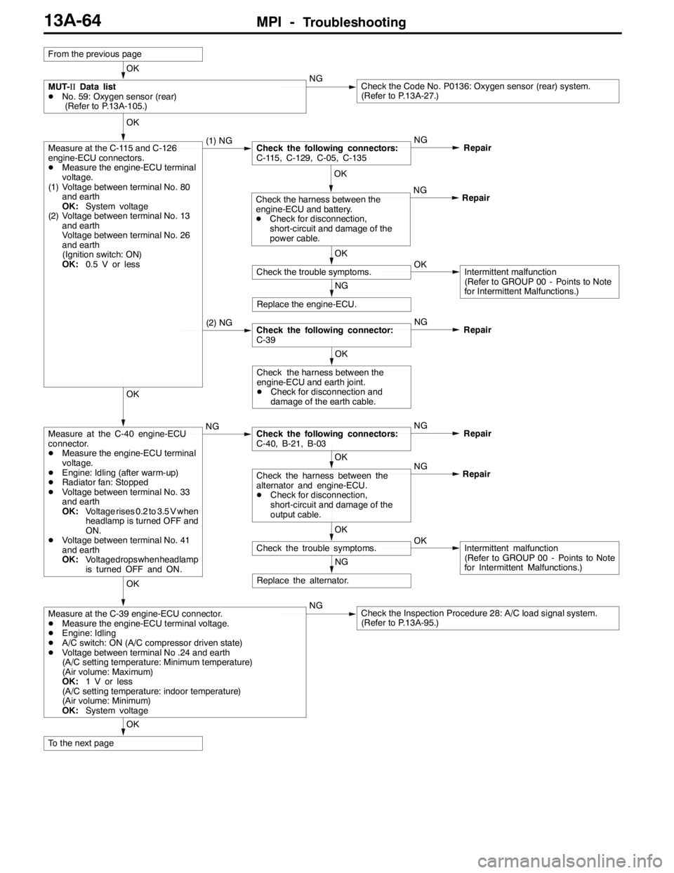
MPI -Troubleshooting13A-64
OK
To the next page
OK
Measure at the C-39 engine-ECU connector.
DMeasure the engine-ECU terminal voltage.
DEngine: Idling
DA/C switch: ON (A/C compressor driven state)
DVoltage between terminal No .24 and earth
(A/C setting temperature: Minimum temperature)
(Air volume: Maximum)
OK:1 V or less
(A/C setting temperature: indoor temperature)
(Air volume: Minimum)
OK:System voltageNGCheck the Inspection Procedure 28: A/C load signal system.
(Refer to P.13A-95.)
NG
Replace the alternator.
OK
Check the trouble symptoms.OKIntermittent malfunction
(Refer to GROUP 00 - Points to Note
for Intermittent Malfunctions.) NG
OK
Check the harness between the
alternator and engine-ECU.
DCheck for disconnection,
short-circuit and damage of the
output cable.Repair
OK
Measure at the C-40 engine-ECU
connector.
DMeasure the engine-ECU terminal
voltage.
DEngine: Idling (after warm-up)
DRadiator fan: Stopped
DVoltage between terminal No. 33
and earth
OK:Voltage rises 0.2 to 3.5 V when
headlamp is turned OFF and
ON.
DVoltage between terminal No. 41
and earth
OK:Voltage drops whenheadlamp
is turned OFF and ON.NGCheck the following connectors:
C-40, B-21, B-03NG
Repair
OK
Check the harness between the
engine-ECU and earth joint.
DCheck for disconnection and
damage of the earth cable.
(2) NGCheck the following connector:
C-39NG
Repair
NG
Replace the engine-ECU.
OK
Check the trouble symptoms.OKIntermittent malfunction
(Refer to GROUP 00 - Points to Note
for Intermittent Malfunctions.) NG
OK
Check the harness between the
engine-ECU and battery.
DCheck for disconnection,
short-circuit and damage of the
power cable.Repair
OK
Measure at the C-115 and C-126
engine-ECU connectors.
DMeasure the engine-ECU terminal
voltage.
(1) Voltage between terminal No. 80
and earth
OK:System voltage
(2) Voltage between terminal No. 13
and earth
Voltage between terminal No. 26
and earth
(Ignition switch: ON)
OK:0.5 V or less(1) NGCheck the following connectors:
C-115, C-129, C-05, C-135NG
Repair
OK
MUT-IIData list
DNo. 59: Oxygen sensor (rear)
(Refer to P.13A-105.)NGCheck the Code No. P0136: Oxygen sensor (rear) system.
(Refer to P.13A-27.)
From the previous page
Page 599 of 1449
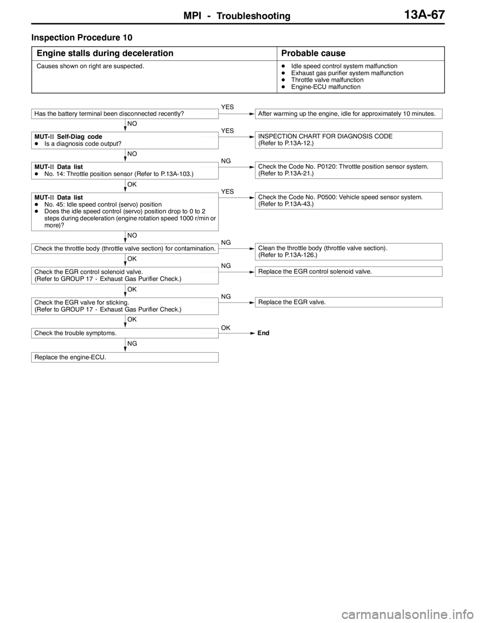
MPI -Troubleshooting13A-67
Inspection Procedure 10
Engine stalls during deceleration
Probable cause
Causes shown on right are suspected.DIdle speed control system malfunction
DExhaust gas purifier system malfunction
DThrottle valve malfunction
DEngine-ECU malfunction
NG
Replace the engine-ECU.
OK
Check the trouble symptoms.OK
End
OK
Check the EGR valve for sticking.
(Refer to GROUP 17 - Exhaust Gas Purifier Check.)NGReplace the EGR valve.
OK
Check the EGR control solenoid valve.
(Refer to GROUP 17 - Exhaust Gas Purifier Check.)NGReplace the EGR control solenoid valve.
NO
Check the throttle body (throttle valve section) for contamination.NGClean the throttle body (throttle valve section).
(Refer to P.13A-126.)
OK
MUT-IIData list
DNo. 45: Idle speed control (servo) position
DDoes the idle speed control (servo) position drop to 0 to 2
steps during deceleration (engine rotation speed 1000 r/min or
more)?YESCheck the Code No. P0500: Vehicle speed sensor system.
(Refer to P.13A-43.)
NO
MUT-IIData list
DNo. 14: Throttle position sensor (Refer to P.13A-103.)NGCheck the Code No. P0120: Throttle position sensor system.
(Refer to P.13A-21.)
NO
MUT-IISelf-Diag code
DIs a diagnosis code output?YESINSPECTION CHART FOR DIAGNOSIS CODE
(Refer to P.13A-12.)
Has the battery terminal been disconnected recently?YESAfter warming up the engine, idle for approximately 10 minutes.
Page 600 of 1449
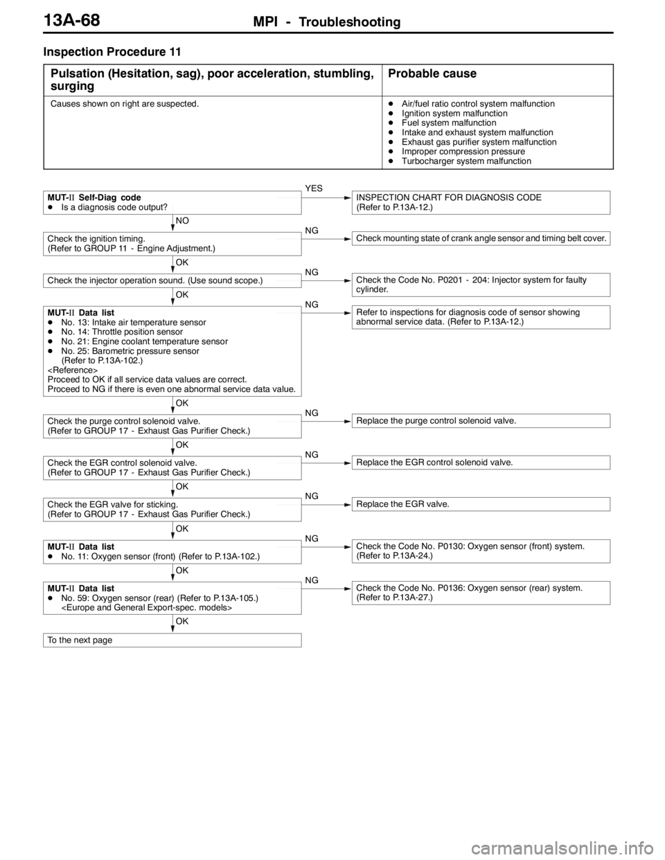
MPI -Troubleshooting13A-68
Inspection Procedure 11
Pulsation (Hesitation, sag), poor acceleration, stumbling,
surging
Probable cause
Causes shown on right are suspected.DAir/fuel ratio control system malfunction
DIgnition system malfunction
DFuel system malfunction
DIntake and exhaust system malfunction
DExhaust gas purifier system malfunction
DImproper compression pressure
DTurbocharger system malfunction
OK
To the next page
OK
MUT-IIData list
DNo. 59: Oxygen sensor (rear) (Refer to P.13A-105.)
(Refer to P.13A-27.)
OK
MUT-IIData list
DNo. 11: Oxygen sensor (front) (Refer to P.13A-102.)NGCheck the Code No. P0130: Oxygen sensor (front) system.
(Refer to P.13A-24.)
OK
Check the EGR valve for sticking.
(Refer to GROUP 17 - Exhaust Gas Purifier Check.)NGReplace the EGR valve.
OK
Check the EGR control solenoid valve.
(Refer to GROUP 17 - Exhaust Gas Purifier Check.)NGReplace the EGR control solenoid valve.
OK
Check the purge control solenoid valve.
(Refer to GROUP 17 - Exhaust Gas Purifier Check.)NGReplace the purge control solenoid valve.
OK
MUT-IIData list
DNo. 13: Intake air temperature sensor
DNo. 14: Throttle position sensor
DNo. 21: Engine coolant temperature sensor
DNo. 25: Barometric pressure sensor
(Refer to P.13A-102.)
Proceed to OK if all service data values are correct.
Proceed to NG if there is even one abnormal service data value.NGRefer to inspections for diagnosis code of sensor showing
abnormal service data. (Refer to P.13A-12.)
OK
Check the injector operation sound. (Use sound scope.)NGCheck the Code No. P0201 - 204: Injector system for faulty
cylinder.
NO
Check the ignition timing.
(Refer to GROUP 11 - Engine Adjustment.)NGCheck mounting state of crank angle sensor and timing belt cover.
MUT-IISelf-Diag code
DIs a diagnosis code output?YESINSPECTION CHART FOR DIAGNOSIS CODE
(Refer to P.13A-12.)
Page 603 of 1449
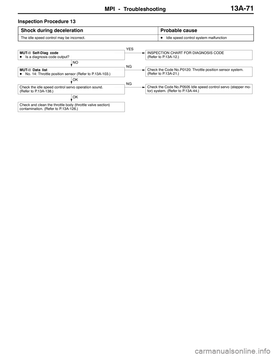
MPI -Troubleshooting13A-71
Inspection Procedure 13
Shock during deceleration
Probable cause
The idle speed control may be incorrect.DIdle speed control system malfunction
OK
Check and clean the throttle body (throttle valve section)
contamination. (Refer to P.13A-126.)
OK
Check the idle speed control servo operation sound.
(Refer to P.13A-138.)NGCheck the Code No.P0505 Idle speed control servo (stepper mo-
tor) system. (Refer to P.13A-44.)
NO
MUT-IIData list
DNo. 14: Throttle position sensor (Refer to P.13A-103.)NGCheck the Code No.P0120: Throttle position sensor system.
(Refer to P.13A-21.)
MUT-IISelf-Diag code
DIs a diagnosis code output?YESINSPECTION CHART FOR DIAGNOSIS CODE
(Refer to P.13A-12.)
Page 604 of 1449
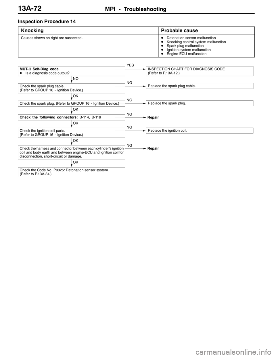
MPI -Troubleshooting13A-72
Inspection Procedure 14
Knocking
Probable cause
Causes shown on right are suspected.DDetonation sensor malfunction
DKnocking control system malfunction
DSpark plug malfunction
DIgnition system malfunction
DEngine-ECU malfunction
OK
Check the Code No. P0325: Detonation sensor system.
(Refer to P.13A-34.)
OK
Check the harness and connector between each cylinder’s ignition
coil and body earth and between engine-ECU and ignition coil for
disconnection, short-circuit or damage.NG
Repair
OK
Check the ignition coil parts.
(Refer to GROUP 16 - Ignition Device.)NGReplace the ignition coil.
OK
Check the following connectors:B-114, B-119NG
Repair
OK
Check the spark plug. (Refer to GROUP 16 - Ignition Device.)NGReplace the spark plug.
NO
Check the spark plug cable.
(Refer to GROUP 16 - Ignition Device.)NGReplace the spark plug cable.
MUT-IISelf-Diag code
DIs a diagnosis code output?YESINSPECTION CHART FOR DIAGNOSIS CODE
(Refer to P.13A-12.)
Page 605 of 1449
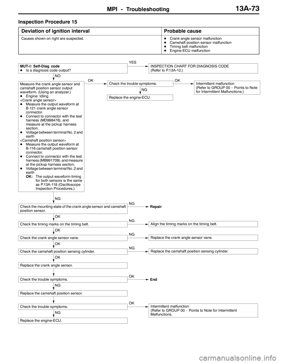
MPI -Troubleshooting13A-73
Inspection Procedure 15
Deviation of ignition interval
Probable cause
Causes shown on right are suspected.DCrank angle sensor malfunction
DCamshaft position sensor malfunction
DTiming belt malfunction
DEngine-ECU malfunction
NG
Replace the engine-ECU.
Check the trouble symptoms.OKIntermittent malfunction
(Refer to GROUP 00 - Points to Note for Intermittent
Malfunctions.
NG
Replace the camshaft position sensor.
Check the trouble symptoms.OK
End
OK
Replace the crank angle sensor.
NG
Replace the engine-ECU.
OK
Check the camshaft position sensing cylinder.NGReplace the camshaft position sensing cylinder.
OK
Check the crank angle sensor vane.NGReplace the crank angle sensor vane.
OK
Check the timing marks on the timing belt.NGAlign the timing marks on the timing belt.
NG
Check the mounting state of the crank angle sensor and camshaft
position sensor.NG
Repair
NO
Measure the crank angle sensor and
camshaft position sensor output
waveform. (Using an analyzer.)
DEngine: Idling
DMeasure the output waveform at
B-121 crank angle sensor
connector.
DConnect to connector with the test
harness (MD998478), and
measure at the pickup harness
section.
DVoltage between terminal No. 2 and
earth
DMeasure the output waveform at
B-116 camshaft position sensor
connector.
DConnect to connector with the test
harness (MB991709), and measure
at the pickup harness section.
DVoltage between terminal No. 2 and
earth
OK:The output waveform timing
for both sensors is the same
as P.13A-118 (Oscilloscope
Inspection Procedures.)OKCheck the trouble symptoms.OKIntermittent malfunction
(Refer to GROUP 00 - Points to Note
for Intermittent Malfunctions.)
MUT-IISelf-Diag code
DIs a diagnosis code output?YESINSPECTION CHART FOR DIAGNOSIS CODE
(Refer to P.13A-12.)