sensor MITSUBISHI LANCER EVOLUTION 2007 Service Repair Manual
[x] Cancel search | Manufacturer: MITSUBISHI, Model Year: 2007, Model line: LANCER EVOLUTION, Model: MITSUBISHI LANCER EVOLUTION 2007Pages: 1449, PDF Size: 56.82 MB
Page 815 of 1449

MANUAL TRANSMISSION - Troubleshooting
Diagnosis
code No.Reference page Diagnosis items
81Electric pump relay systemopen circuit or short-circuit22A-29
82electric pump malfunction
or pressure sensor defect22A-30
84AYC control errorRefer to
GROUP 27B.
85ACD control error-
NOTE
Code No.85 is not a code number output due to malfunction, but a code number output when control
for the 4WD-ECU to protect the ACD is stopped in excessive driving. ACD control can be recovered
by turning the ignition switch ON to OFF to ON.
Page 817 of 1449
MANUAL TRANSMISSION - Troubleshooting
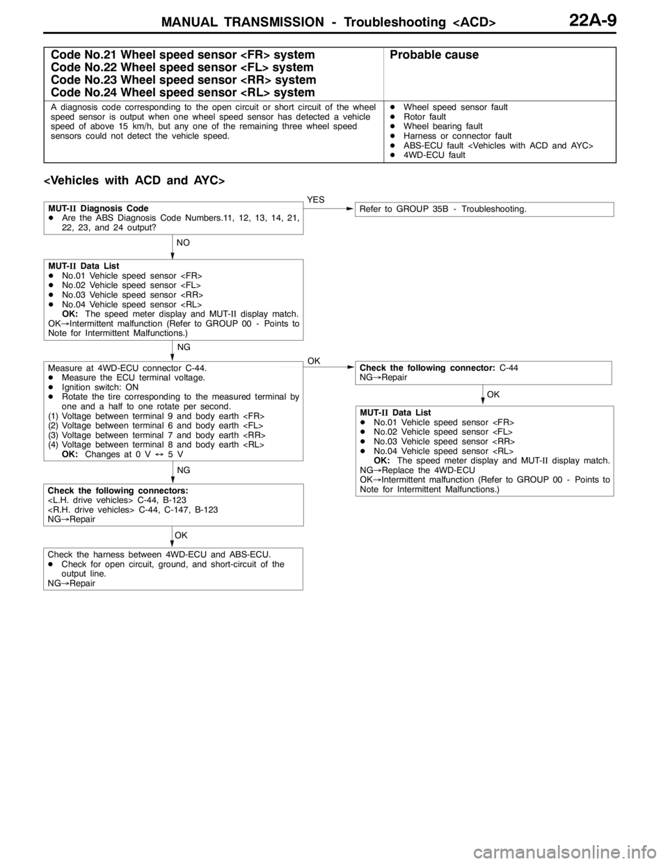
Code No.21 Wheel speed sensor
Code No.22 Wheel speed sensor
Code No.23 Wheel speed sensor
Code No.24 Wheel speed sensor
A diagnosis code corresponding to the open circuit or short circuit of the wheel
speed sensor is output when one wheel speed sensor has detected a vehicle
speed of above 15 km/h, but any one of the remaining three wheel speed
sensors could not detect the vehicle speed.DWheel speed sensor fault
DRotor fault
DWheel bearing fault
DHarness or connector fault
DABS-ECU fault
D4WD-ECU fault
OKNGYES
NO
OK
Measure at 4WD-ECU connector C-44.
DMeasure the ECU terminal voltage.
DIgnition switch: ON
DRotate the tire corresponding to the measured terminal by
one and a half to one rotate per second.
(1) Voltage between terminal 9 and body earth
(2) Voltage between terminal 6 and body earth
(3) Voltage between terminal 7 and body earth
(4) Voltage between terminal 8 and body earth
OK:Changes at 0 V↔5VCheck the following connector:C-44
NG→Repair
Check the following connectors:
NG→Repair
MUT-IIDiagnosis Code
DAre the ABS Diagnosis Code Numbers.11, 12, 13, 14, 21,
22, 23, and 24 output?Refer to GROUP 35B - Troubleshooting.
NG
MUT-IIData List
DNo.01 Vehicle speed sensor
DNo.02 Vehicle speed sensor
DNo.03 Vehicle speed sensor
DNo.04 Vehicle speed sensor
OK:The speed meter display and MUT-IIdisplay match.
OK→Intermittent malfunction (Refer to GROUP 00 - Points to
Note for Intermittent Malfunctions.)
OK
Check the harness between 4WD-ECU and ABS-ECU.
DCheck for open circuit, ground, and short-circuit of the
output line.
NG→Repair
MUT-IIData List
DNo.01 Vehicle speed sensor
DNo.02 Vehicle speed sensor
DNo.03 Vehicle speed sensor
DNo.04 Vehicle speed sensor
OK:The speed meter display and MUT-IIdisplay match.
NG→Replace the 4WD-ECU
OK→Intermittent malfunction (Refer to GROUP 00 - Points to
Note for Intermittent Malfunctions.)
Page 818 of 1449
MANUAL TRANSMISSION - Troubleshooting
OK OK NG
OK NG
OK OK
OK
NG
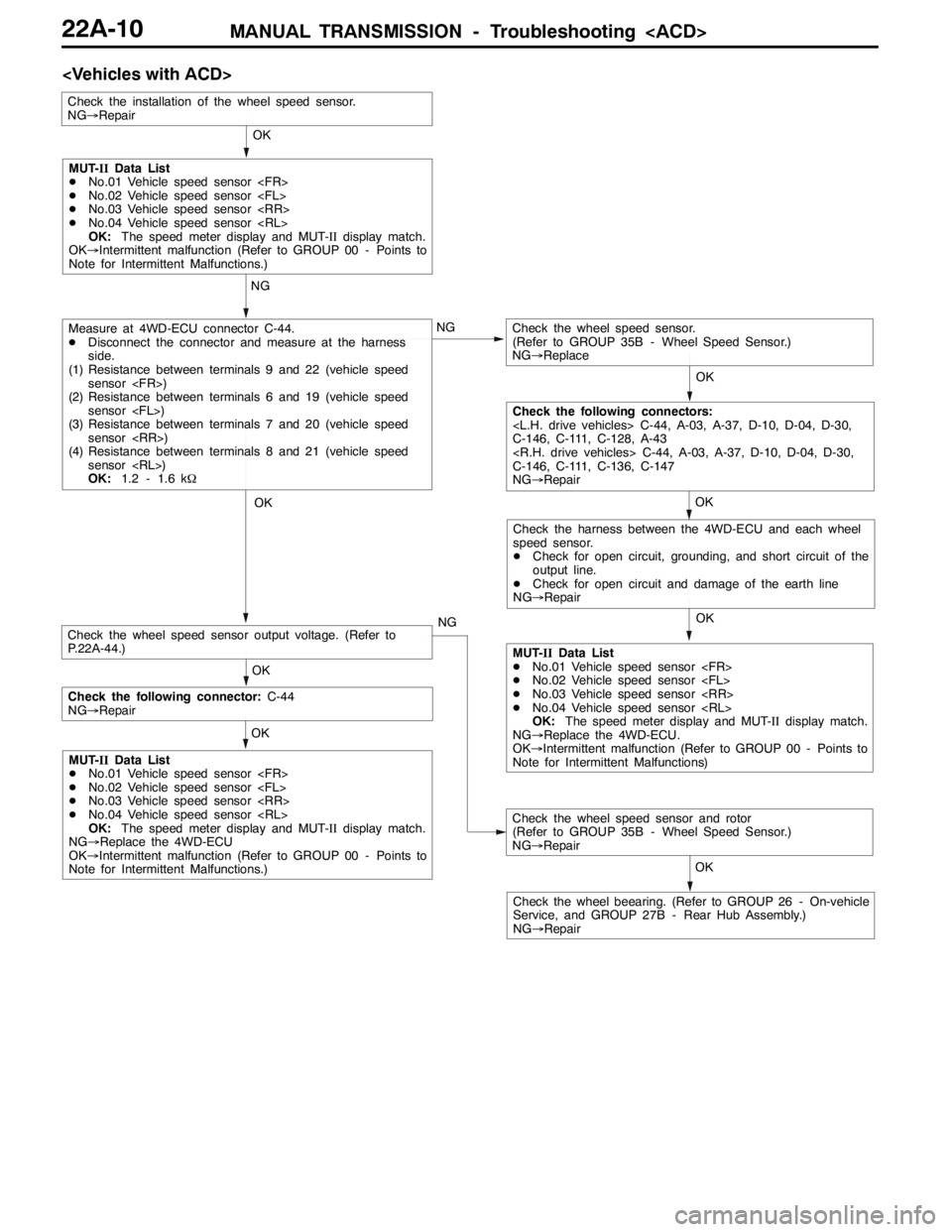
Measure at 4WD-ECU connector C-44.
DDisconnect the connector and measure at the harness
side.
(1) Resistance between terminals 9 and 22 (vehicle speed
sensor
(2) Resistance between terminals 6 and 19 (vehicle speed
sensor
(3) Resistance between terminals 7 and 20 (vehicle speed
sensor
(4) Resistance between terminals 8 and 21 (vehicle speed
sensor
OK:1.2 - 1.6 kΩCheck the wheel speed sensor.
(Refer to GROUP 35B - Wheel Speed Sensor.)
NG→Replace
Check the installation of the wheel speed sensor.
NG→Repair
Check the wheel speed sensor and rotor
(Refer to GROUP 35B - Wheel Speed Sensor.)
NG→Repair
Check the wheel beearing. (Refer to GROUP 26 - On-vehicle
Service, and GROUP 27B - Rear Hub Assembly.)
NG→RepairOK
MUT-IIData List
DNo.01 Vehicle speed sensor
DNo.02 Vehicle speed sensor
DNo.03 Vehicle speed sensor
DNo.04 Vehicle speed sensor
OK:The speed meter display and MUT-IIdisplay match.
OK→Intermittent malfunction (Refer to GROUP 00 - Points to
Note for Intermittent Malfunctions.)
Check the following connectors:
C-146, C-111, C-128, A-43
C-146, C-111, C-136, C-147
NG→Repair
Check the harness between the 4WD-ECU and each wheel
speed sensor.
DCheck for open circuit, grounding, and short circuit of the
output line.
DCheck for open circuit and damage of the earth line
NG→Repair
MUT-IIData List
DNo.01 Vehicle speed sensor
DNo.02 Vehicle speed sensor
DNo.03 Vehicle speed sensor
DNo.04 Vehicle speed sensor
OK:The speed meter display and MUT-IIdisplay match.
NG→Replace the 4WD-ECU.
OK→Intermittent malfunction (Refer to GROUP 00 - Points to
Note for Intermittent Malfunctions) OK
Check the following connector:C-44
NG→Repair
MUT-IIData List
DNo.01 Vehicle speed sensor
DNo.02 Vehicle speed sensor
DNo.03 Vehicle speed sensor
DNo.04 Vehicle speed sensor
OK:The speed meter display and MUT-IIdisplay match.
NG→Replace the 4WD-ECU
OK→Intermittent malfunction (Refer to GROUP 00 - Points to
Note for Intermittent Malfunctions.)
Check the wheel speed sensor output voltage. (Refer to
P.22A-44.)
Page 819 of 1449
MANUAL TRANSMISSION - Troubleshooting
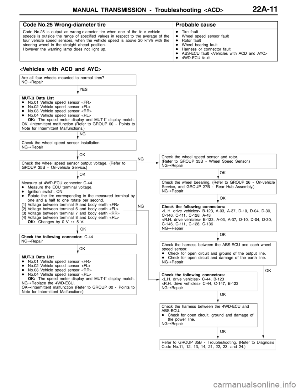
Code No.25 Wrong-diameter tireProbable cause
Code No.25 is output as wrong-diameter tire when one of the four vehicle
speeds is outside the range of specified values in respect to the average of the
four vehicle speed sensors, when the vehicle speed is above 20 km/h with the
steering wheel in the straight ahead position.
However the warning lamp does not light up.DTire fault
DWheel speed sensor fault
DRotor fault
DWheel bearing fault
DHarness or connector fault
DABS-ECU fault
D4WD-ECU fault
OK NG
OK
Check the following connector:C-44
NG→Repair
Check the following connectors:
NG→Repair OKYES
OK
OK
Check the wheel speed sensor and rotor.
(Refer to GROUP 35B - Wheel Speed Sensor.)
NG→Repair
Check the wheel speed sensor output voltage. (Refer to
GROUP 35B - On-vehicle Service.)OK
Check the wheel speed sensor installation.
NG→Repair
NG
OK
Check the wheel beearing. (Refer to GROUP 26 - On-vehicle
Service, and GROUP 27B - Rear Hub Assembly.)
NG→Repair
OK
Check the following connectors:
C-146, C-111, C-128, A-43
C-146, C-111, C-128, C-136
NG→Repair NG
MUT-IIData List
DNo.01 Vehicle speed sensor
DNo.02 Vehicle speed sensor
DNo.03 Vehicle speed sensor
DNo.04 Vehicle speed sensor
OK:The speed meter display and MUT-IIdisplay match.
OK→Intermittent malfunction (Refer to GROUP 00 - Points to
Note for Intermittent Malfunctions.)
Measure at 4WD-ECU connector C-44.
DMeasure the ECU terminal voltage.
DIgnition switch: ON
DRotate the tire corresponding to the measured terminal by
one and a half to one rotate per second.
(1) Voltage between terminal 9 and body earth
(2) Voltage between terminal 6 and body earth
(3) Voltage between terminal 7 and body earth
(4) Voltage between terminal 8 and body earth
OK:Changes by 0 V↔5V.
MUT-IIData List
DNo.01 Vehicle speed sensor
DNo.02 Vehicle speed sensor
DNo.03 Vehicle speed sensor
DNo.04 Vehicle speed sensor
OK:The speed meter display and MUT-IIdisplay match.
NG→Replace the 4WD-ECU.
OK→Intermittent malfunction (Refer to GROUP 00 - Points to
Note for Intermittent Malfunctions)
Refer to GROUP 35B - Troubleshooting. (Refer to Diagnosis
Code No.11, 12, 13, 14, 21, 22, 23, and 24.)
Are all four wheels mounted to normal tires?
NO→Repair
Check the harness between the ABS-ECU and each wheel
speed sensor.
DCheck for open circuit and ground of the output line.
DCheck for open circuit and damage of the earth line.
NG→Repair
OK
Check the harness between the 4WD-ECU and
ABS-ECU.
DCheck for open circuit, ground and damage of
the power line.
NG→RepairOK
Page 820 of 1449
MANUAL TRANSMISSION - Troubleshooting
OK OK NG
OK NG
OK OK
OK
NG
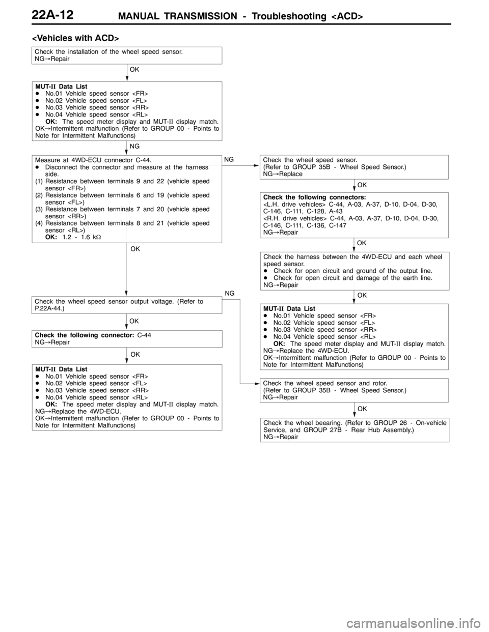
Measure at 4WD-ECU connector C-44.
DDisconnect the connector and measure at the harness
side.
(1) Resistance between terminals 9 and 22 (vehicle speed
sensor
(2) Resistance between terminals 6 and 19 (vehicle speed
sensor
(3) Resistance between terminals 7 and 20 (vehicle speed
sensor
(4) Resistance between terminals 8 and 21 (vehicle speed
sensor
OK:1.2 - 1.6 kΩCheck the wheel speed sensor.
(Refer to GROUP 35B - Wheel Speed Sensor.)
NG→Replace
Check the installation of the wheel speed sensor.
NG→Repair
Check the wheel speed sensor and rotor.
(Refer to GROUP 35B - Wheel Speed Sensor.)
NG→Repair
Check the wheel beearing. (Refer to GROUP 26 - On-vehicle
Service, and GROUP 27B - Rear Hub Assembly.)
NG→RepairOK
MUT-IIData List
DNo.01 Vehicle speed sensor
DNo.02 Vehicle speed sensor
DNo.03 Vehicle speed sensor
DNo.04 Vehicle speed sensor
OK:The speed meter display and MUT-IIdisplay match.
OK→Intermittent malfunction (Refer to GROUP 00 - Points to
Note for Intermittent Malfunctions)
Check the following connectors:
C-146, C-111, C-128, A-43
C-146, C-111, C-136, C-147
NG→Repair
Check the harness between the 4WD-ECU and each wheel
speed sensor.
DCheck for open circuit and ground of the output line.
DCheck for open circuit and damage of the earth line.
NG→Repair
MUT-IIData List
DNo.01 Vehicle speed sensor
DNo.02 Vehicle speed sensor
DNo.03 Vehicle speed sensor
DNo.04 Vehicle speed sensor
OK:The speed meter display and MUT-IIdisplay match.
NG→Replace the 4WD-ECU.
OK→Intermittent malfunction (Refer to GROUP 00 - Points to
Note for Intermittent Malfunctions) OK
Check the following connector:C-44
NG→Repair
MUT-IIData List
DNo.01 Vehicle speed sensor
DNo.02 Vehicle speed sensor
DNo.03 Vehicle speed sensor
DNo.04 Vehicle speed sensor
OK:The speed meter display and MUT-IIdisplay match.
NG→Replace the 4WD-ECU.
OK→Intermittent malfunction (Refer to GROUP 00 - Points to
Note for Intermittent Malfunctions)
Check the wheel speed sensor output voltage. (Refer to
P.22A-44.)
Page 821 of 1449
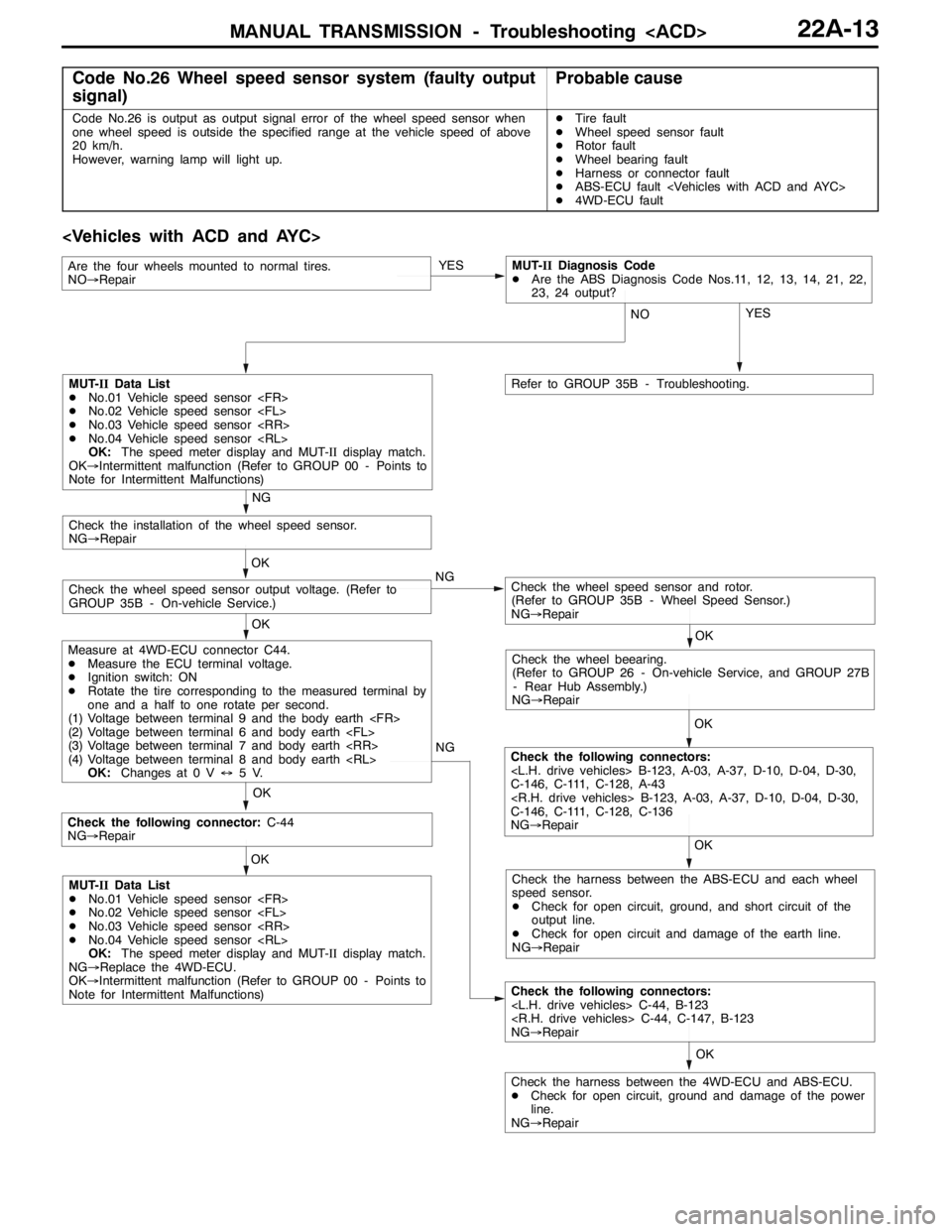
MANUAL TRANSMISSION - Troubleshooting
Code No.26 Wheel speed sensor system (faulty output
signal)Probable cause
Code No.26 is output as output signal error of the wheel speed sensor when
one wheel speed is outside the specified range at the vehicle speed of above
20 km/h.
However, warning lamp will light up.DTire fault
DWheel speed sensor fault
DRotor fault
DWheel bearing fault
DHarness or connector fault
DABS-ECU fault
D4WD-ECU fault
OK NG
OK
Check the following connector:C-44
NG→Repair
Check the following connectors:
NG→Repair OK
Check the harness between the 4WD-ECU and ABS-ECU.
DCheck for open circuit, ground and damage of the power
line.
NG→RepairYES
OK OK
Check the wheel speed sensor and rotor.
(Refer to GROUP 35B - Wheel Speed Sensor.)
NG→RepairCheck the wheel speed sensor output voltage. (Refer to
GROUP 35B - On-vehicle Service.)OK
Check the installation of the wheel speed sensor.
NG→Repair
NG
OK
Check the wheel beearing.
(Refer to GROUP 26 - On-vehicle Service, and GROUP 27B
- Rear Hub Assembly.)
NG→Repair
OK
Check the following connectors:
C-146, C-111, C-128, A-43
C-146, C-111, C-128, C-136
NG→Repair NG
MUT-IIData List
DNo.01 Vehicle speed sensor
DNo.02 Vehicle speed sensor
DNo.03 Vehicle speed sensor
DNo.04 Vehicle speed sensor
OK:The speed meter display and MUT-IIdisplay match.
OK→Intermittent malfunction (Refer to GROUP 00 - Points to
Note for Intermittent Malfunctions)
Measure at 4WD-ECU connector C44.
DMeasure the ECU terminal voltage.
DIgnition switch: ON
DRotate the tire corresponding to the measured terminal by
one and a half to one rotate per second.
(1) Voltage between terminal 9 and the body earth
(2) Voltage between terminal 6 and body earth
(3) Voltage between terminal 7 and body earth
(4) Voltage between terminal 8 and body earth
OK:Changes at 0 V↔5V.
MUT-IIData List
DNo.01 Vehicle speed sensor
DNo.02 Vehicle speed sensor
DNo.03 Vehicle speed sensor
DNo.04 Vehicle speed sensor
OK:The speed meter display and MUT-IIdisplay match.
NG→Replace the 4WD-ECU.
OK→Intermittent malfunction (Refer to GROUP 00 - Points to
Note for Intermittent Malfunctions)Check the harness between the ABS-ECU and each wheel
speed sensor.
DCheck for open circuit, ground, and short circuit of the
output line.
DCheck for open circuit and damage of the earth line.
NG→Repair YES
NO
Refer to GROUP 35B - Troubleshooting.
Are the four wheels mounted to normal tires.
NO→RepairMUT-IIDiagnosis Code
DAre the ABS Diagnosis Code Nos.11, 12, 13, 14, 21, 22,
23, 24 output?
Page 822 of 1449
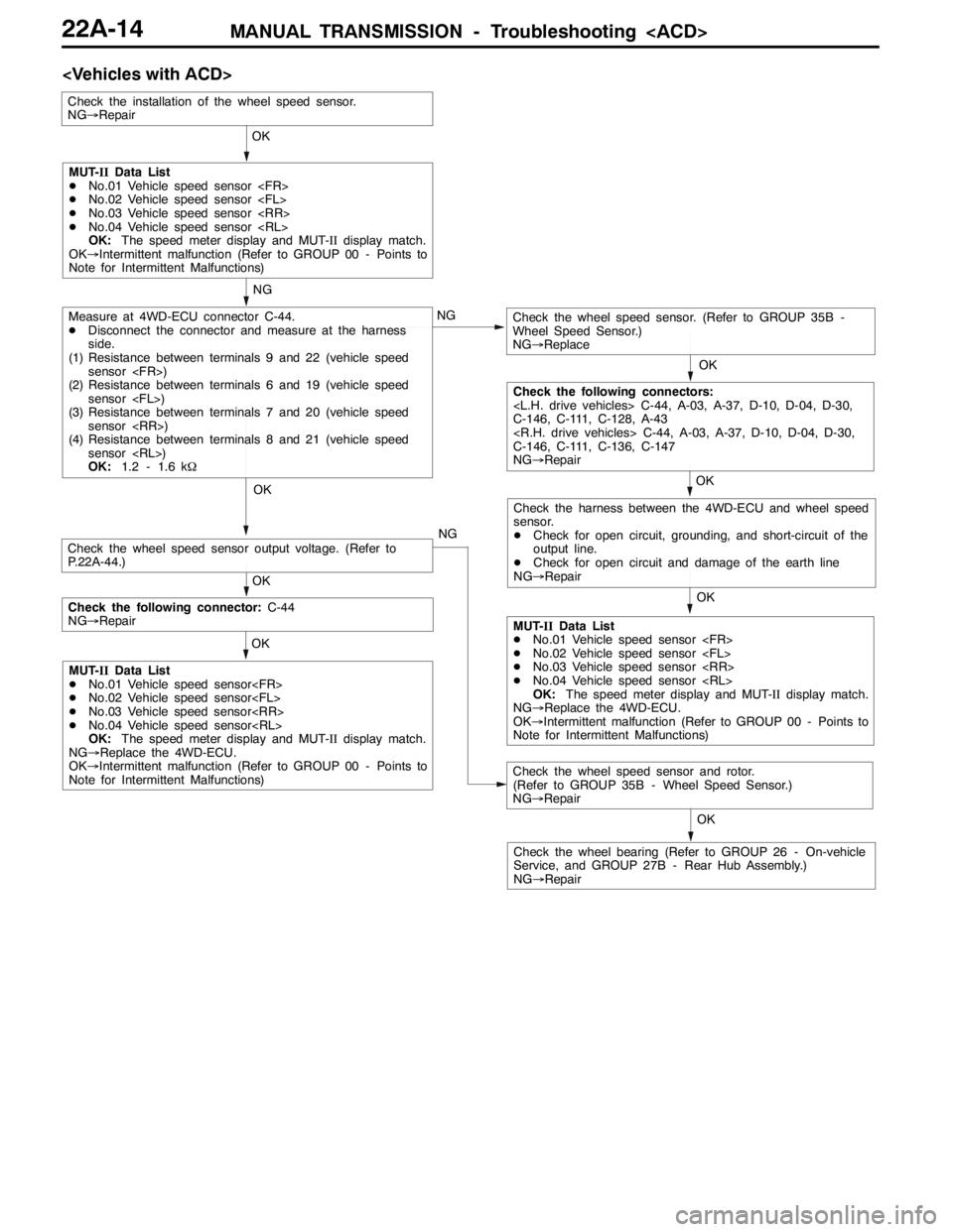
MANUAL TRANSMISSION - Troubleshooting
OK OK NG
OK NG
OK OK
OK
NG
Measure at 4WD-ECU connector C-44.
DDisconnect the connector and measure at the harness
side.
(1) Resistance between terminals 9 and 22 (vehicle speed
sensor
(2) Resistance between terminals 6 and 19 (vehicle speed
sensor
(3) Resistance between terminals 7 and 20 (vehicle speed
sensor
(4) Resistance between terminals 8 and 21 (vehicle speed
sensor
OK:1.2 - 1.6 kΩCheck the wheel speed sensor. (Refer to GROUP 35B -
Wheel Speed Sensor.)
NG→Replace
Check the installation of the wheel speed sensor.
NG→Repair
Check the wheel speed sensor and rotor.
(Refer to GROUP 35B - Wheel Speed Sensor.)
NG→Repair
Check the wheel bearing (Refer to GROUP 26 - On-vehicle
Service, and GROUP 27B - Rear Hub Assembly.)
NG→RepairOK
MUT-IIData List
DNo.01 Vehicle speed sensor
DNo.02 Vehicle speed sensor
DNo.03 Vehicle speed sensor
DNo.04 Vehicle speed sensor
OK:The speed meter display and MUT-IIdisplay match.
OK→Intermittent malfunction (Refer to GROUP 00 - Points to
Note for Intermittent Malfunctions)
Check the following connectors:
C-146, C-111, C-128, A-43
C-146, C-111, C-136, C-147
NG→Repair
Check the harness between the 4WD-ECU and wheel speed
sensor.
DCheck for open circuit, grounding, and short-circuit of the
output line.
DCheck for open circuit and damage of the earth line
NG→Repair
MUT-IIData List
DNo.01 Vehicle speed sensor
DNo.02 Vehicle speed sensor
DNo.03 Vehicle speed sensor
DNo.04 Vehicle speed sensor
OK:The speed meter display and MUT-IIdisplay match.
NG→Replace the 4WD-ECU.
OK→Intermittent malfunction (Refer to GROUP 00 - Points to
Note for Intermittent Malfunctions) OK
Check the following connector:C-44
NG→Repair
MUT-IIData List
DNo.01 Vehicle speed sensor
DNo.02 Vehicle speed sensor
DNo.03 Vehicle speed sensor
DNo.04 Vehicle speed sensor
OK:The speed meter display and MUT-IIdisplay match.
NG→Replace the 4WD-ECU.
OK→Intermittent malfunction (Refer to GROUP 00 - Points to
Note for Intermittent Malfunctions)
Check the wheel speed sensor output voltage. (Refer to
P.22A-44.)
Page 823 of 1449
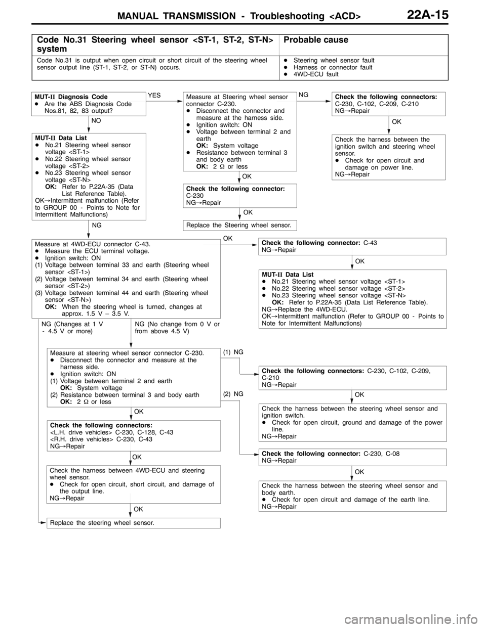
MANUAL TRANSMISSION - Troubleshooting
Code No.31 Steering wheel sensor
systemProbable cause
Code No.31 is output when open circuit or short circuit of the steering wheel
sensor output line (ST-1, ST-2, or ST-N) occurs.DSteering wheel sensor fault
DHarness or connector fault
D4WD-ECU fault
OK NG NO
OK
MUT-IIData List
DNo.21 Steering wheel sensor
voltage
DNo.22 Steering wheel sensor
voltage
DNo.23 Steering wheel sensor
voltage
OK:Refer to P.22A-35 (Data
List Reference Table).
OK→Intermittent malfunction (Refer
to GROUP 00 - Points to Note for
Intermittent Malfunctions)
Check the following connector:C-43
NG→Repair YES
MUT-IIDiagnosis Code
DAre the ABS Diagnosis Code
Nos.81, 82, 83 output?
MUT-IIData List
DNo.21 Steering wheel sensor voltage
DNo.22 Steering wheel sensor voltage
DNo.23 Steering wheel sensor voltage
OK:Refer to P.22A-35 (Data List Reference Table).
NG→Replace the 4WD-ECU.
OK→Intermittent malfunction (Refer to GROUP 00 - Points to
Note for Intermittent Malfunctions)
NG (No change from 0 V or
from above 4.5 V)
Measure at 4WD-ECU connector C-43.
DMeasure the ECU terminal voltage.
DIgnition switch: ON
(1) Voltage between terminal 33 and earth (Steering wheel
sensor
(2) Voltage between terminal34and earth (Steering wheel
sensor
(3) Voltage between terminal44 andearth (Steering wheel
sensor
OK:When the steering wheel is turned, changes at
approx. 1.5 V – 3.5 V.
(1) NG
NG (Changes at 1 V
- 4.5 V or more)
OK
Check the harness between the steering wheel sensor and
ignition switch.
DCheck for open circuit, ground and damage of the power
line.
NG→Repair
Check the following connectors:C-230, C-102, C-209,
C-210
NG→Repair
OKOK
Check the following connectors:
NG→Repair
OK
Check the harness between 4WD-ECU and steering
wheel sensor.
DCheck for open circuit, short circuit, and damage of
the output line.
NG→Repair
Replace the steering wheel sensor.
Replace the Steering wheel sensor.
OK
OK
Check the following connector:
C-230
NG→RepairNG
Measure at Steering wheel sensor
connector C-230.
DDisconnect the connector and
measure at the harness side.
DIgnition switch: ON
DVoltage between terminal 2 and
earth
OK:System voltage
DResistance between terminal 3
and body earth
OK:2Ωor less
OK
Check the following connectors:
C-230, C-102, C-209, C-210
NG→Repair
Check the harness between the
ignition switch and steering wheel
sensor.
DCheck for open circuit and
damage on power line.
NG→Repair
(2) NG
OK
Check the harness between the steering wheel sensor and
body earth.
DCheck for open circuit and damage of the earth line.
NG→Repair
Check the following connector:C-230, C-08
NG→Repair
Measure at steering wheel sensor connector C-230.
DDisconnect the connector and measure at the
harness side.
DIgnition switch: ON
(1) Voltage between terminal 2 and earth
OK:System voltage
(2) Resistance between terminal 3 and body earth
OK:2Ωor less
Page 824 of 1449
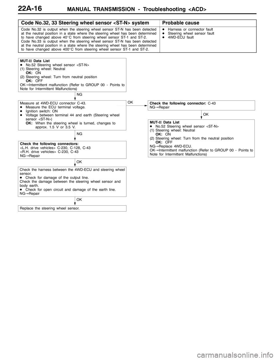
MANUAL TRANSMISSION - Troubleshooting
Code No.32, 33 Steering wheel sensor
Code No.32 is output when the steering wheel sensor ST-N has been detected
at the neutral position in a state where the steering wheel has been determined
to have changed above 40_C from steering wheel sensor ST-1 and ST-2.
Code No.33 is output when the steering wheel sensor ST-N has been detected
at the neutral position in a state where the steering wheel has been determined
to have changed above 400_C from steering wheel sensor ST-1 and ST-2.DHarness or connector fault
DSteering wheel sensor fault
D4WD-ECU fault
NG
OK
MUT-IIData List
DNo.52 Steering wheel sensor
(1) Steering wheel: Neutral
OK:ON
(2) Steering wheel: Turn from neutral position
OK:OFF
OK→Intermittent malfunction (Refer to GROUP 00 - Points to
Note for Intermittent Malfunctions)
Check the following connector:C-43
NG→Repair
NG
Check the following connectors:
NG→Repair
OK
Replace the steering wheel sensor.OK
Measure at 4WD-ECU connector C-43.
DMeasure the ECU terminal voltage.
DIgnition switch: ON
DVoltage between terminal 44 and earth (Steering wheel
sensor
OK:When the steering wheel is turned, changes to
approx. 1.5 V or 3.5 V.
MUT-IIData List
DNo.52 Steering wheel sensor
(1) Steering wheel: Neutral
OK:ON
(2) Steering wheel: Turn from the neutral position
OK:OFF
NG→Replace 4WD-ECU.
OK→Intermittent malfunction (Refer to GROUP 00 - Points to
Note for Intermittent Malfunctions)
OK
Check the harness between the 4WD-ECU and steering wheel
sensor.
DCheck for damage of the output line.
Check the damage between the steering wheel sensor and
body earth.
DCheck for open circuit and damage of the earth line.
NG→Repair
Page 825 of 1449
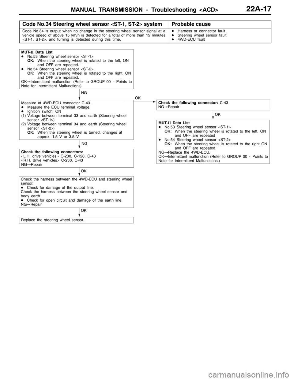
MANUAL TRANSMISSION - Troubleshooting
Code No.34 Steering wheel sensor
Code No.34 is output when no change in the steering wheel sensor signal at a
vehicle speed of above 15 km/h is detected for a total of more than 15 minutes
DSteering wheel sensor fault
D4WD-ECU fault
NG
OK
MUT-IIData List
DNo.53 Steering wheel sensor
OK:When the steering wheel is rotated to the left, ON
and OFF are repeated.
DNo.54 Steering wheel sensor
OK:When the steering wheel is rotated to the right, ON
and OFF are repeated.
OK→Intermittent malfunction (Refer to GROUP 00 - Points to
Note for Intermittent Malfunctions)
Check the following connector:C-43
NG→Repair
NG
Check the following connectors:
NG→Repair
OK
Replace the steering wheel sensor.OK
OK
Check the harness between the 4WD-ECU and steering wheel
sensor.
DCheck for damage of the output line.
Check the harness between the steering wheel sensor and
body earth.
DCheck for open circuit and damage of the earth line.
NG→Repair
Measure at 4WD-ECU connector C-43.
DMeasure the ECU terminal voltage.
DIgnition switch: ON
(1) Voltage between terminal 33 and earth (Steering wheel
sensor
(2) Voltage between terminal 34 and earth (Steering wheel
sensor
OK:When the steering wheel is turned, changes at
approx. 1.5 V or 3.5 V
MUT-IIData List
DNo.53 Steering wheel sensor
OK:When the steering wheel is rotated to the left, ON
and OFF are repeated
DNo.54 Steering wheel sensor
OK:When the steering wheel is rotated to the right ON
and OFF are repeated.
NG→Replace the 4WD-ECU.
OK→Intermittent malfunction (Refer to GROUP 00 - Points to
Note for Intermittent Malfunctions.)