MITSUBISHI LANCER EVOLUTION 2007 Service Repair Manual
LANCER EVOLUTION 2007
MITSUBISHI
MITSUBISHI
https://www.carmanualsonline.info/img/19/57084/w960_57084-0.png
MITSUBISHI LANCER EVOLUTION 2007 Service Repair Manual
Trending: engine coolant, mirror, fuel cap, clutch, low oil pressure, automatic transmission, air condition
Page 161 of 1449
CIRCUIT DIAGRAMS
H1J00X09AB
B-63
Page 162 of 1449
CIRCUIT DIAGRAMS
H1J00X09BA
B-64
J/C (CONTINUED)
Page 163 of 1449
CIRCUIT DIAGRAMS
H1J00X09BB
B-65
Page 164 of 1449
CIRCUIT DIAGRAMS
H1J00X09CA
B-66
J/C (CONTINUED)
Page 165 of 1449
CIRCUIT DIAGRAMS
H1J00X09CB
B-67
Page 166 of 1449
CIRCUIT DIAGRAMSB-68
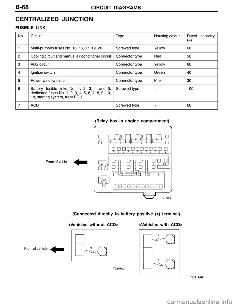
CENTRALIZED JUNCTION
FUSIBLE LINK
No.CircuitTypeHousing colourRated capacity
(A)
1Multi-purpoes fuses No. 15, 16, 17, 19, 20Screwed typeYellow60
2Cooling circuit and manual air conditioner circuitConnector typeRed50
3ABS circuitConnector typeYellow60
4Ignition switchConnector typeGreen40
5Power window circuitConnector typePink30
6Battery, fusible links No. 1, 2, 3, 4 and 5,
dedicated fuses No. 1, 2, 3, 4, 5, 6, 7, 8, 9, 10,
18, starting system, front-ECUScrewed type-100
7ACDScrewed type-60
(Relay box in engine compartment)
Front of vehicle
(Connected directly to battery positive (+) terminal)
Front of vehicle
1
234
5
6 7
6
Page 167 of 1449

CIRCUIT DIAGRAMSB-69
DEDICATED FUSE
Power supply
circuitNo.Rated
capacity (A)Identification
colourCircuit
Battery/alternator
(FusiblelinkNo6)
115BlueSpare connectors
(FusiblelinkNo.6)210RedHorn relay
320YellowEngine control relay and ignition control relay
410RedA/C compressor
515BlueABS-ECU, 4WD-ECU, high-mounted stop lamp and rear
combination lamp
630GreenCondenser fan motor
77.5BrownAlternator
810RedETACS-ECU
9---
1015BlueFuel pump
Front-ECU
(Headlamprelay:
1110RedHeadlamp
(Headlamp relay:
HI)1210RedHeadlamp
Front-ECU
(Headlamprelay:
1310RedFront combination lamp
(Headlamp relay:
LO)1410RedFront combination lamp
Front-ECU
(Tail lamp relay)157.5BrownHeater control unit or A/C-ECU, clock, combination
meter, fog lamp switch, hazard warning switch, radio,
rear combination lamp, headlamp leveling switch, front
combination lamp, cigarette lighter illumination lamp,
ashtray illumination lamp, ACD mode changeover switch
and inter cooler water splay switch
167.5BrownFront combination lamp, licence plate lamp and rear
combination lamp
Ignition switch
(ACC)1710RedClock
Battery/alternator
(Fusible link No. 6)1810RedEngine-ECU, ETACS-ECU, front-ECU and combination
meter
-19---
Fusible link No. 52120YellowIntercooler water splay
-22---
Ignition switch
(IG2)23---
-24---
Battery/alternator
(Fusible link No. 6)2530GreenCondenser fan motor
Page 168 of 1449
CIRCUIT DIAGRAMSB-70
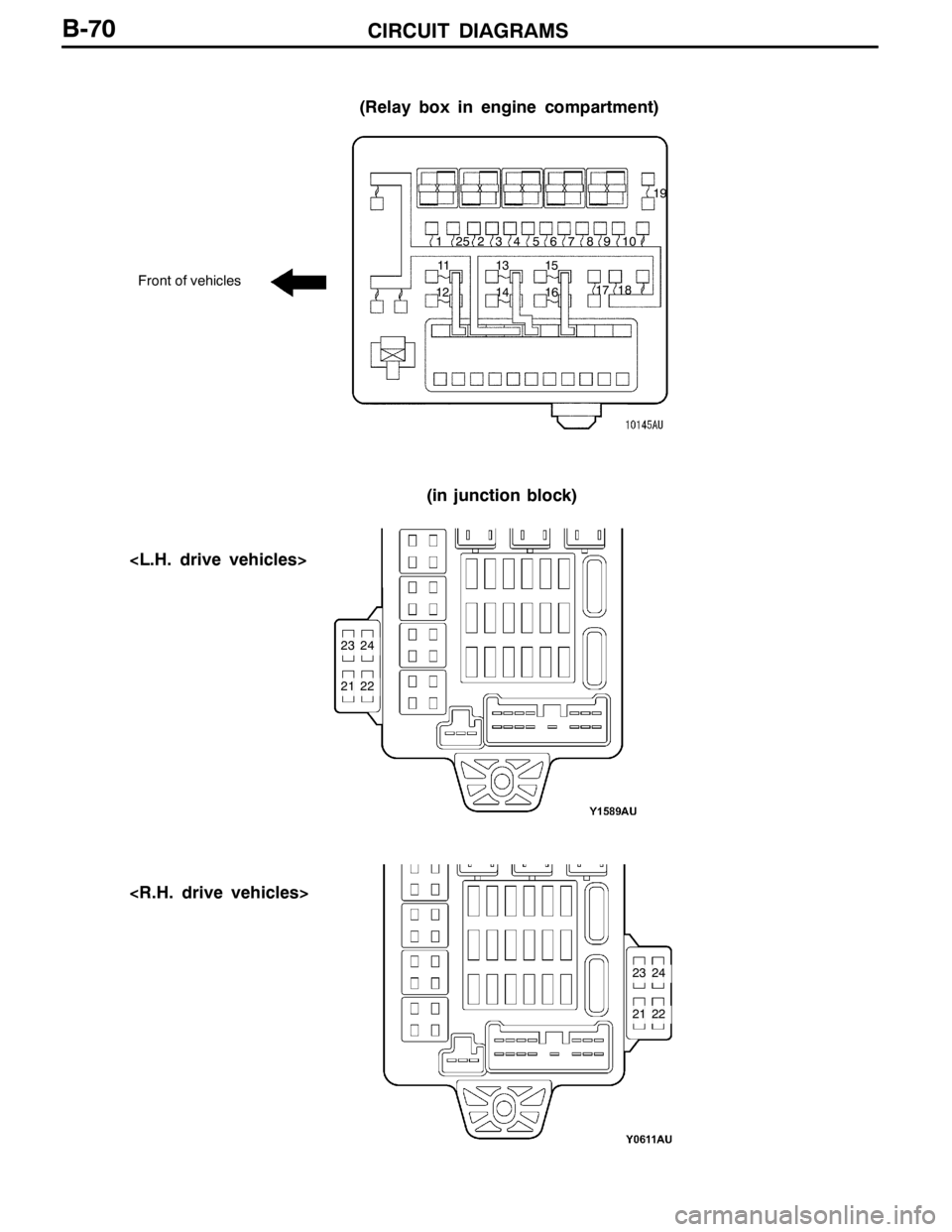
(Relay box in engine compartment)
Front of vehicles
(in junction block)
1234
1213
1415 56 7 8
1617 1819
910
11
21
2324
22
21
2324
22 25
Page 169 of 1449

CIRCUIT DIAGRAMSB-71
MULTI-PURPOSE FUSE (In junction block)
Power supply
circuitNo.Rated
capacity (A)Identification
colourCircuit
Ignition
switch
IG1110RedIgnition coil
switch
27.5BrownColumn switch, combination meter, ETACS-ECU,
SRS-ECU, vehicle speed sensor and ACD mode
changeover switch
37.5BrownETACS-ECU and SRS-ECU
4---
IG257.5BrownA/C compressor relay, A/C-ECU, blower relay,
condenser fan relay, defogger relay, front-ECU,
4WD-ECU, steering wheel sensor and inter cooler
water splay relay
Multi-purpose fuse
No. 20 (Defogger
relay)6---
Ignition
switch
ACC720YellowFront-ECU and windshield wiper motor
switch
IG187.5BrownEngine-ECU and fuel pump relay (1) and fuel pump
relay (2)
ACC915BlueCigarette lighter
10---
117.5BrownA/C-ECU and remote controlled mirror switch
IG2127.5BrownABS-ECU, G-sensor (longitudinal) and G-sensor
(lateral)
ACC13---
14---
Fusible link No. 1
Battery/alternator
1515BlueDiagnosis connector
Battery/alternator
1610RedRear fog lamp relay
1710RedETACS-ECU
18---
1930GreenBlower motor and resistor
2030GreenDefogger
Page 170 of 1449
CIRCUIT DIAGRAMSB-72
1 23456
789
10 11 12
13 14 15 16 17 1819
20
Trending: service reset, odometer, differential, oil capacity, battery capacity, oil level, lights


