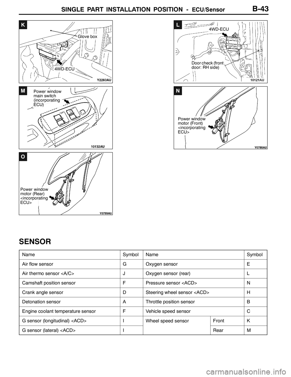
MITSUBISHI LANCER EVOLUTION 2007 Service Repair Manual
LANCER EVOLUTION 2007
MITSUBISHI
MITSUBISHI
https://www.carmanualsonline.info/img/19/57084/w960_57084-0.png
MITSUBISHI LANCER EVOLUTION 2007 Service Repair Manual
Trending: towing, oil level, drain bolt, oil change, overheating, weight, checking oil
Page 141 of 1449
Page 142 of 1449
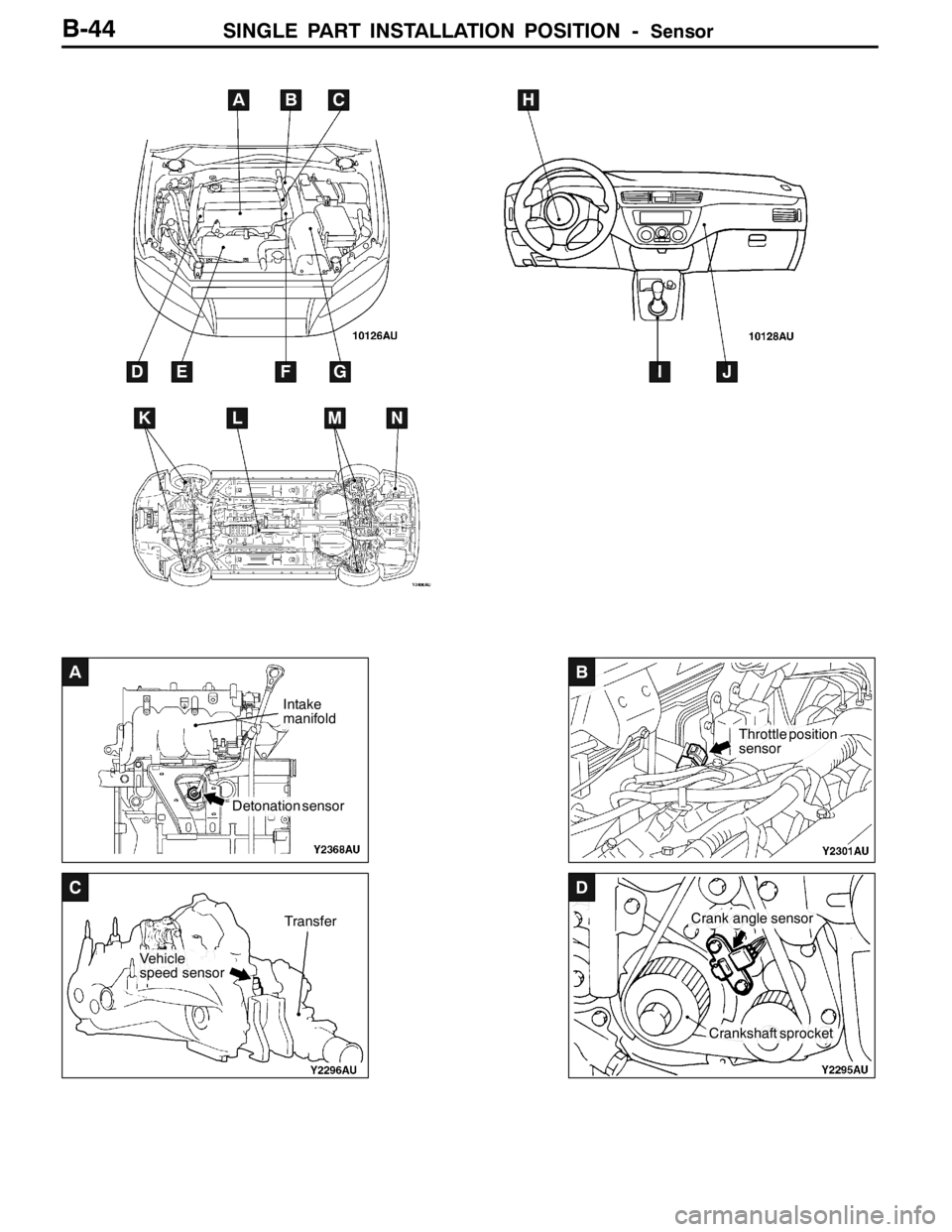
SINGLE PART INSTALLATION POSITION -Sensor
A
Intake
manifold
Detonation sensor
B
Throttle position
sensor
C
Vehicle
speed sensor
Transfer
D
Crank angle sensor
Crankshaft sprocket
B-44
ABC
DEFG
H
IJ
KLMN
Page 143 of 1449
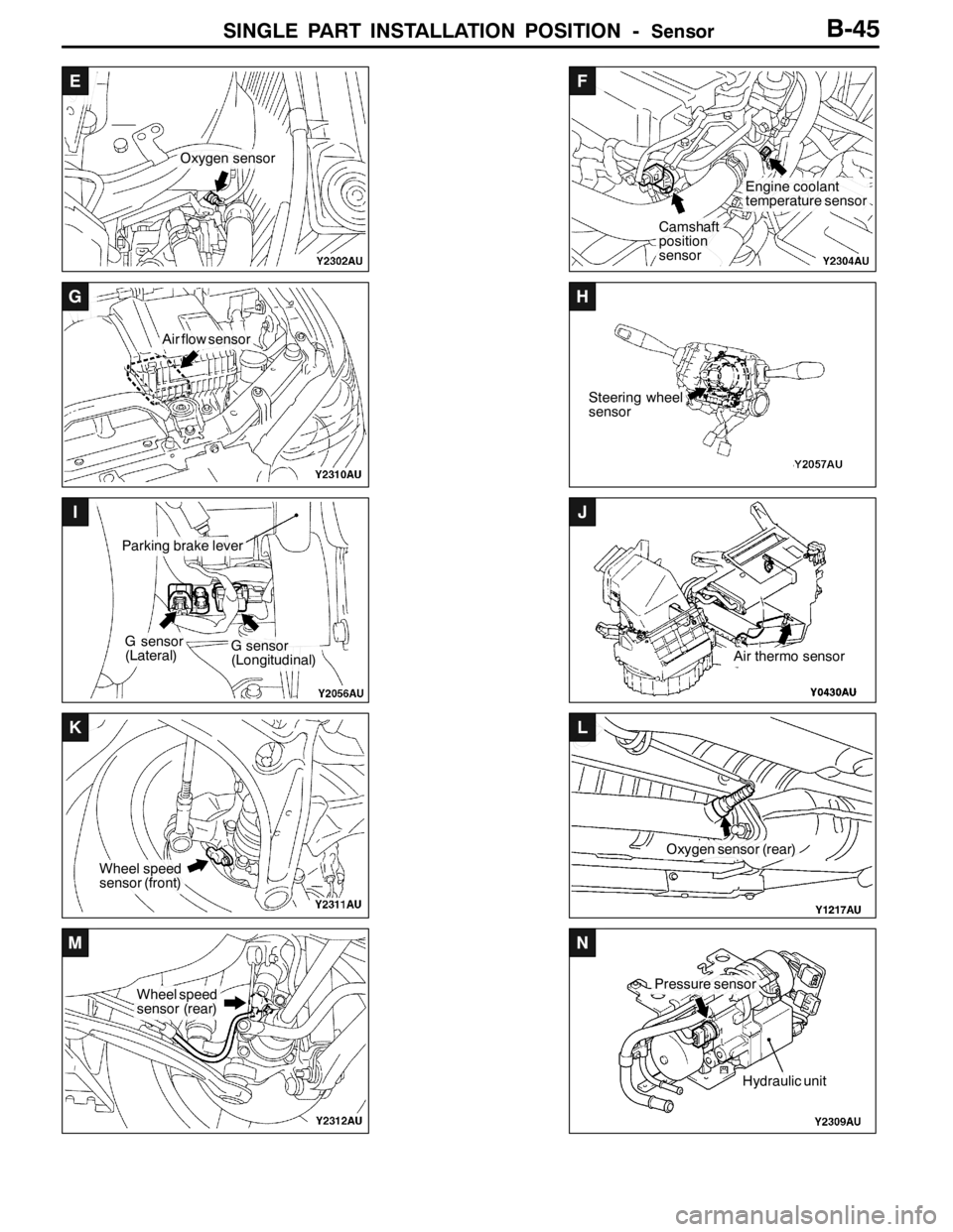
SINGLE PART INSTALLATION POSITION -Sensor
E
Oxygen sensor
F
Camshaft
position
sensor
Engine coolant
temperature sensor
G
Air flow sensor
H
Steering wheel
sensor
I
G sensor
(Lateral)
Parking brake lever
G sensor
(Longitudinal)
J
Air thermo sensor
K
Wheel speed
sensor (front)
L
Oxygen sensor (rear)
M
Wheel speed
sensor (rear)
N
Pressure sensor
Hydraulic unit
B-45
Page 144 of 1449
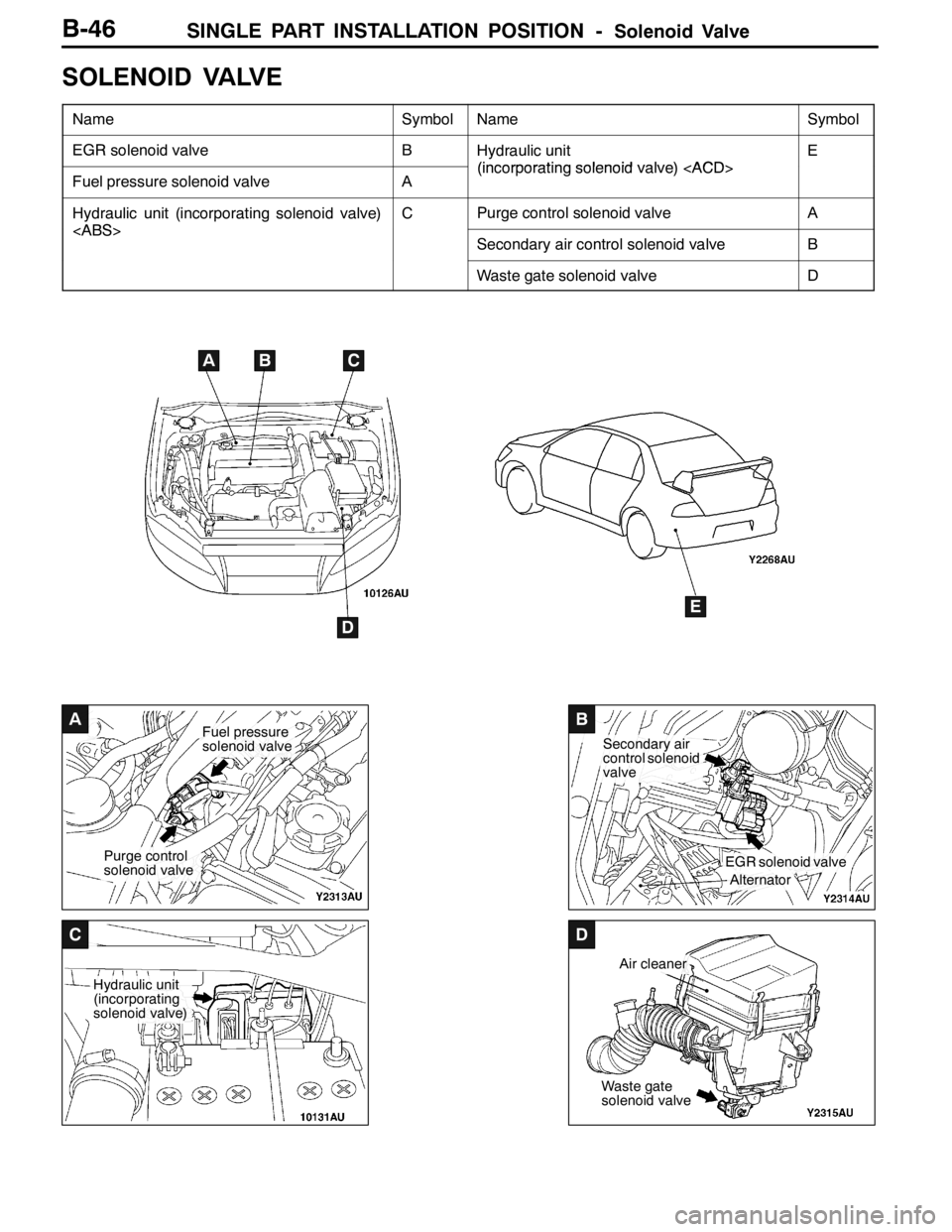
SINGLE PART INSTALLATION POSITION -Solenoid Valve
A
Purge control
solenoid valve
Fuel pressure
solenoid valveB
Secondary air
control solenoid
valve
Alternator
EGR solenoid valve
C
Hydraulic unit
(incorporating
solenoid valve)
D
Air cleaner
Waste gate
solenoid valve
B-46
SOLENOID VALVE
NameSymbolNameSymbol
EGR solenoid valveBHydraulic unit
(incorporatingsolenoidvalve)
E
Fuel pressure solenoid valveA(incorporating solenoid valve)
Hydraulic unit (incorporating solenoid valve)
CPurge control solenoid valveA
Secondary air control solenoid valveB
Waste gate solenoid valveD
ABC
D
E
Page 145 of 1449
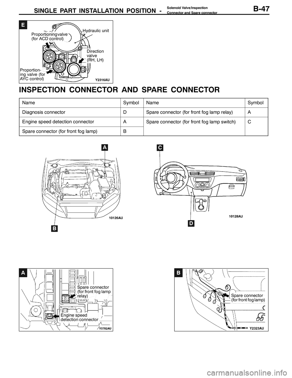
SINGLE PART INSTALLATION POSITION -Solenoid Valve/Inspection
Connector and Spare connector
E
Proportioning valve
(for ACD control)
Proportion-
ing valve (for
AYC control)
Hydraulic unit
Direction
valve
(RH, LH)
A
Engine speed
detection connector
Spare connector
(for front fog lamp
relay)
B
Spare connector
(for front fog lamp)
B-47
INSPECTION CONNECTOR AND SPARE CONNECTOR
NameSymbolNameSymbol
Diagnosis connectorDSpare connector (for front fog lamp relay)A
Engine speed detection connectorASpare connector (for front fog lamp switch)C
Spare connector (for front fog lamp)B
A
B
C
D
Page 146 of 1449
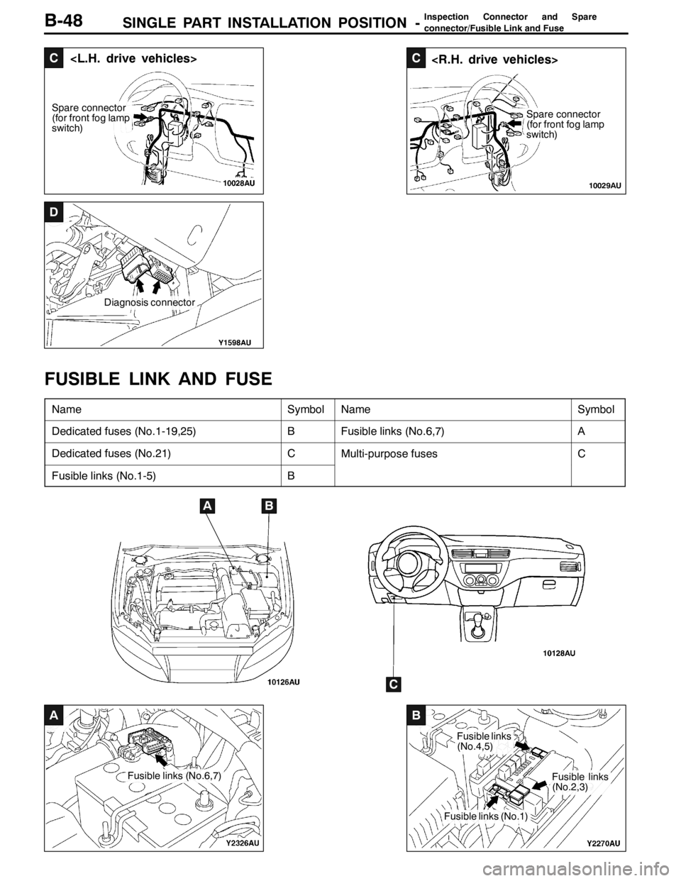
SINGLE PART INSTALLATION POSITION -Inspection Connector and Spare
connector/Fusible Link and Fuse
C
Spare connector
(for front fog lamp
switch)
C
Spare connector
(for front fog lamp
switch)
10029AU
D
Diagnosis connector
A
Fusible links (No.6,7)
B
Fusible links
(No.4,5)
Fusible links (No.1)
Fusible links
(No.2,3)
B-48
FUSIBLE LINK AND FUSE
NameSymbolNameSymbol
Dedicated fuses (No.1-19,25)BFusible links (No.6,7)A
Dedicated fuses (No.21)CMulti-purpose fusesC
Fusible links (No.1-5)B
AB
C
Page 147 of 1449
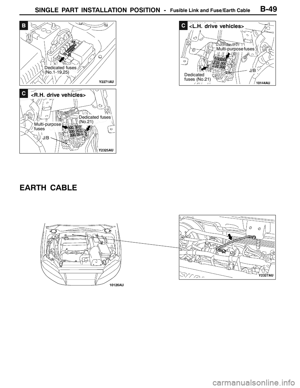
SINGLE PART INSTALLATION POSITION -Fusible Link and Fuse/Earth Cable
B
Dedicated fuses
(No.1-19,25)
C
Dedicated
fuses (No.21)
Multi-purpose fuses
J/B
C
Multi-purpose
fuses
Dedicated fuses
(No.21)
J/B
B-49
EARTH CABLE
Page 148 of 1449
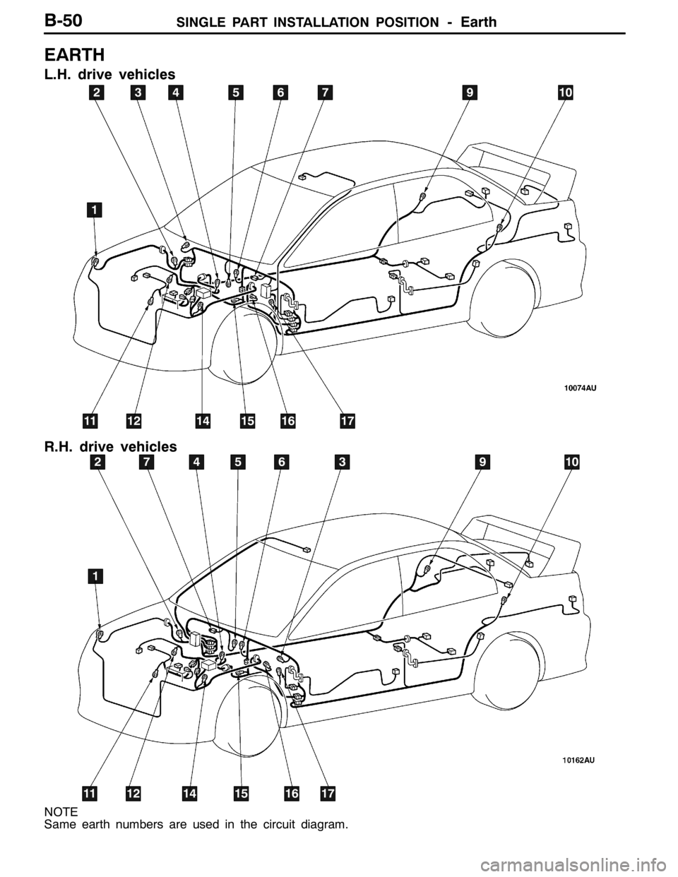
SINGLE PART INSTALLATION POSITION- EarthB-50
EARTH
L.H. drive vehicles
1
234567910
111214151617
R.H. drive vehicles
1
234567910
111214151617
NOTE
Same earth numbers are used in the circuit diagram.
Page 149 of 1449
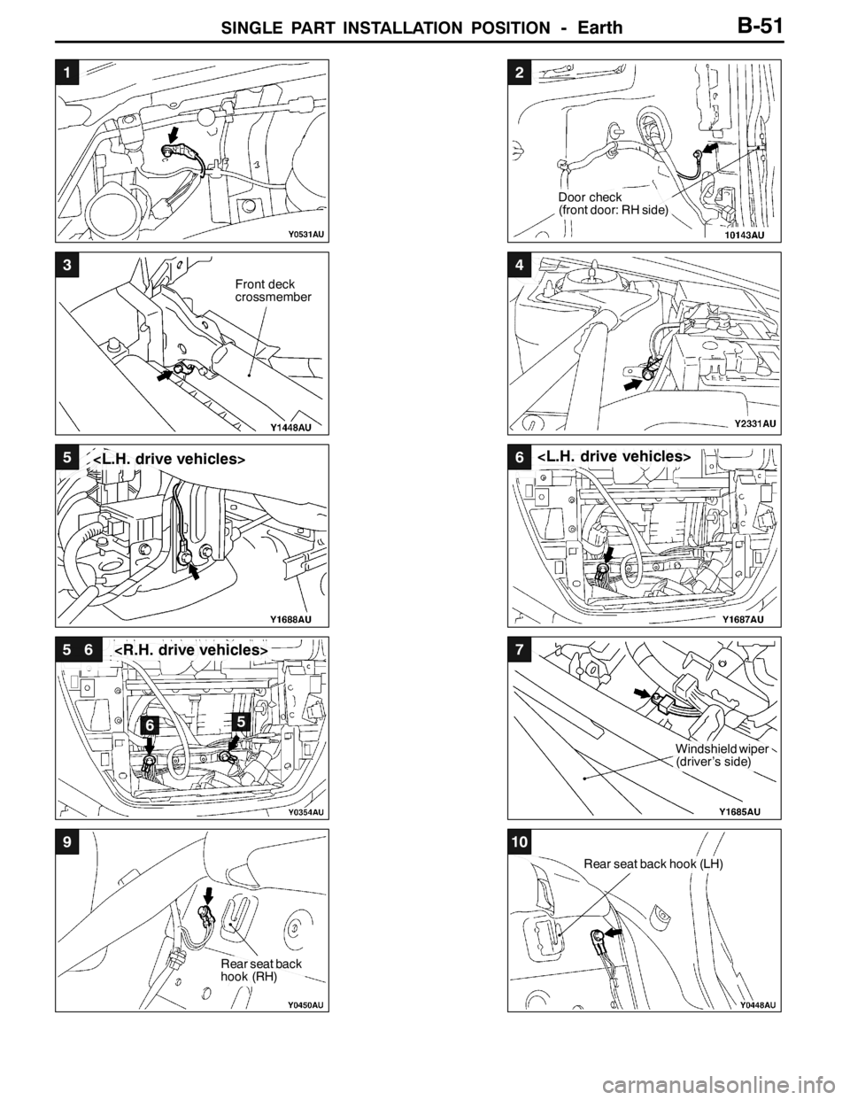
SINGLE PART INSTALLATION POSITION- Earth
12
Door check
(front door: RH side)
3
Front deck
crossmember
4
56
56
56
7
Windshield wiper
(driver’s side)
9
Rear seat back
hook (RH)
10
Rear seat back hook (LH)
B-51
Page 150 of 1449
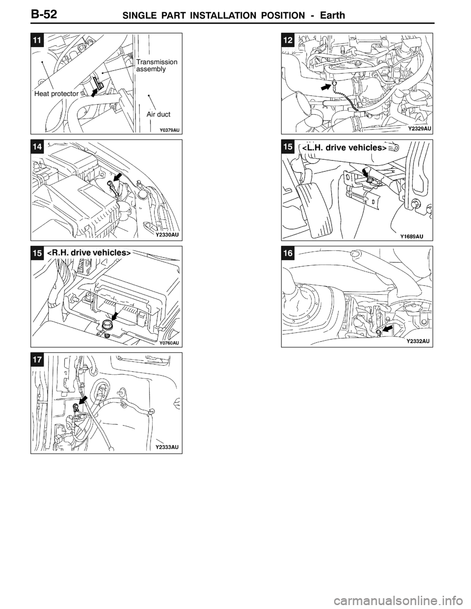
SINGLE PART INSTALLATION POSITION- Earth
11
Heat protector
Transmission
assembly
Air duct
12
1415
1516
17
B-52
Trending: fuel pressure, key battery, suspension, check engine, recommended oil, radio antenna, wheel
