MITSUBISHI LANCER EVOLUTION 2007 Service Repair Manual
LANCER EVOLUTION 2007
MITSUBISHI
MITSUBISHI
https://www.carmanualsonline.info/img/19/57084/w960_57084-0.png
MITSUBISHI LANCER EVOLUTION 2007 Service Repair Manual
Trending: wipers, ground clearance, set clock, radio, charging, to pair, wheel torque
Page 861 of 1449
MANUAL TRANSMISSION - Transmission Assembly22A-53
10
10 11
9
1412 88
13
48±5 N·m
48±5 N·m
48±5 N·m
48±5 N·m
9.0±1.0 N·m
26±5 N·m
82±7 N·m*
47±7 N·m*
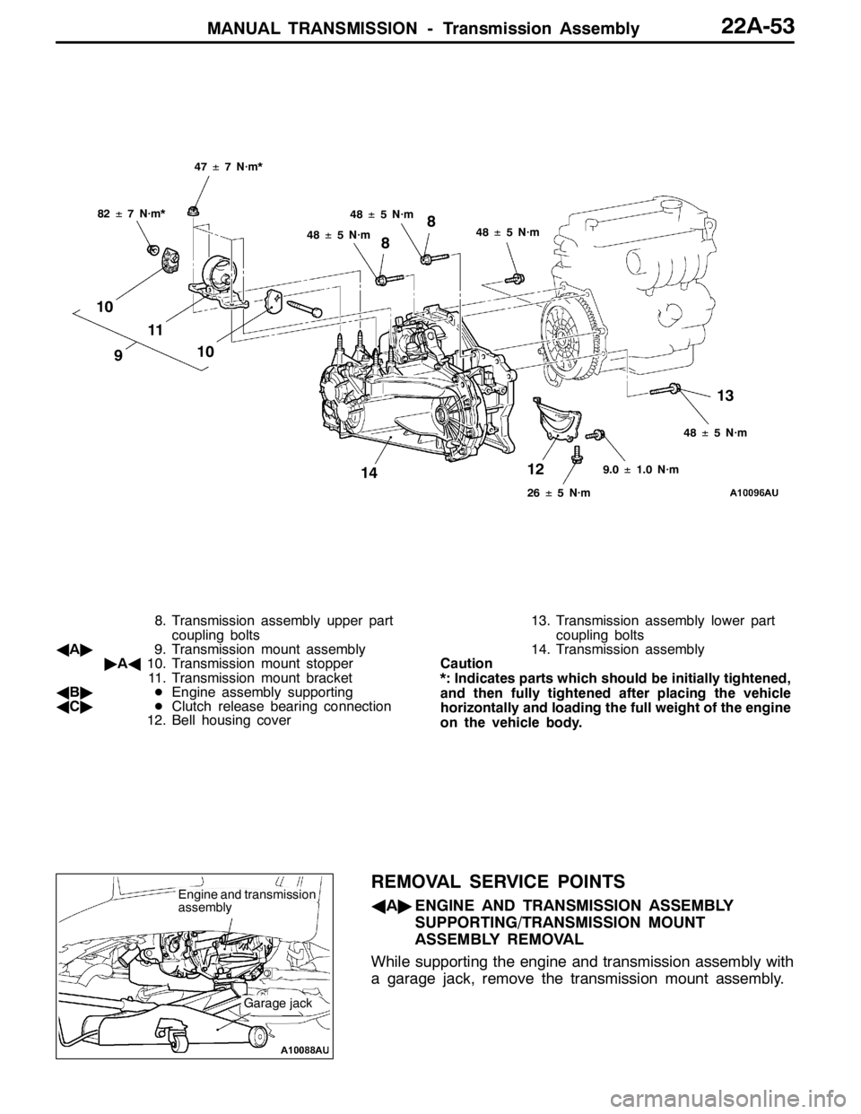
8. Transmission assembly upper part
coupling bolts
AA"9. Transmission mount assembly
"AA10. Transmission mount stopper
11. Transmission mount bracket
AB"DEngine assembly supporting
AC"DClutch release bearing connection
12. Bell housing cover13. Transmission assembly lower part
coupling bolts
14. Transmission assembly
Caution
*: Indicates parts which should be initially tightened,
and then fully tightened after placing the vehicle
horizontally and loading the full weight of the engine
on the vehicle body.
REMOVAL SERVICE POINTS
AA"ENGINE AND TRANSMISSION ASSEMBLY
SUPPORTING/TRANSMISSION MOUNT
ASSEMBLY REMOVAL
While supporting the engine and transmission assembly with
a garage jack, remove the transmission mount assembly.Engine and transmission
assembly
Garage jack
Page 862 of 1449

MANUAL TRANSMISSION - Transmission Assembly22A-54
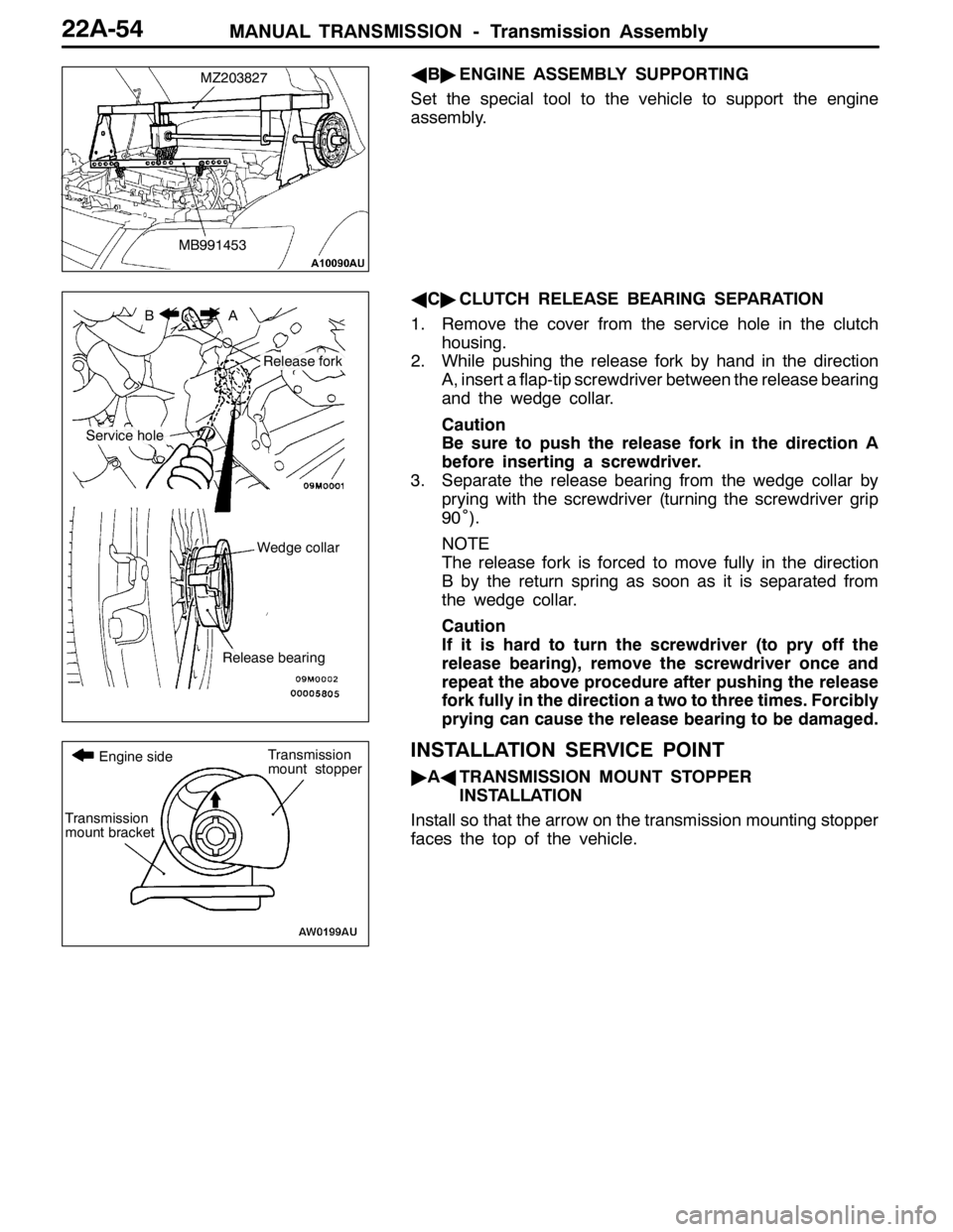
AB"ENGINE ASSEMBLY SUPPORTING
Set the special tool to the vehicle to support the engine
assembly.
AC"CLUTCH RELEASE BEARING SEPARATION
1. Remove the cover from the service hole in the clutch
housing.
2. While pushing the release fork by hand in the direction
A, insert a flap-tip screwdriver between the release bearing
and the wedge collar.
Caution
Be sure to push the release fork in the direction A
before inserting a screwdriver.
3. Separate the release bearing from the wedge collar by
prying with the screwdriver (turning the screwdriver grip
90˚).
NOTE
The release fork is forced to move fully in the direction
B by the return spring as soon as it is separated from
the wedge collar.
Caution
If it is hard to turn the screwdriver (to pry off the
release bearing), remove the screwdriver once and
repeat the above procedure after pushing the release
fork fully in the direction a two to three times. Forcibly
prying can cause the release bearing to be damaged.
INSTALLATION SERVICE POINT
"AATRANSMISSION MOUNT STOPPER
INSTALLATION
Install so that the arrow on the transmission mounting stopper
faces the top of the vehicle.
MZ203827
MB991453
BA
Service hole
Release fork
Wedge collar
Release bearing
Transmission
mount bracket
Transmission
mount stopper Engine side
Page 863 of 1449
MANUAL TRANSMISSION -4WD-ECU
with ACD and AYC>22A-55
4WD-ECU
AYC>
REMOVAL AND INSTALLATION
Pre-removal and Post-installation Operation
DCowl Side Trim Removal and Installation. (Refer to GROUP 52A - Trims.)
DFront floor Console Removal and Installation. (Refer to GROUP 52A - Floor Console.)
4.9�¶0.9 N��m
4WD-ECU
4.9�¶0.9 N��m
4WD-ECU
Page 864 of 1449

MANUAL TRANSMISSION -Sensor, Switch and Relay
or vehicles with ACD and AYC>22A-56
SENSOR, SWITCH AND RELAY
VEHICLES WITH ACD AND AYC>
REMOVAL AND INSTALLATION
Caution
Before removing the steering wheel and air bag module assembly, be sure to refer to GROUP
52B Precautions in Servicing and Airbag Module Clock Spring.
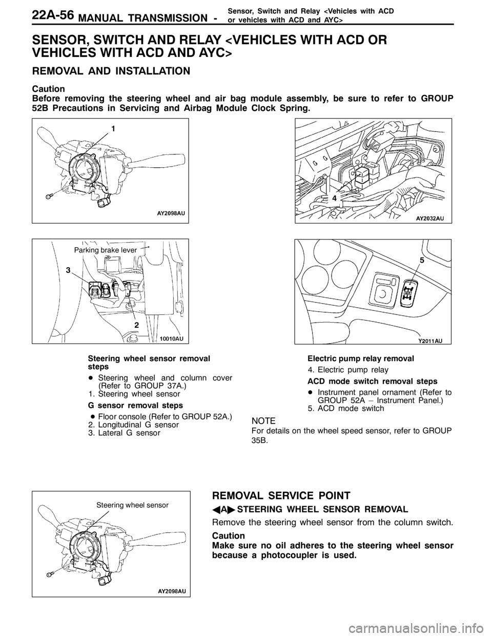
1
3
2
4
5
Parking brake lever
Steering wheel sensor removal
steps
DSteering wheel and column cover
(Refer to GROUP 37A.)
1. Steering wheel sensor
G sensor removal steps
DFloor console (Refer to GROUP 52A.)
2. Longitudinal G sensor
3. Lateral G sensorElectric pump relay removal
4. Electric pump relay
ACD mode switch removal steps
DInstrument panel ornament (Refer to
GROUP 52A – Instrument Panel.)
5. ACD mode switch
NOTE
For details on the wheel speed sensor, refer to GROUP
35B.
REMOVAL SERVICE POINT
AA"STEERING WHEEL SENSOR REMOVAL
Remove the steering wheel sensor from the column switch.
Caution
Make sure no oil adheres to the steering wheel sensor
because a photocoupler is used.Steering wheel sensor
Page 865 of 1449
MANUAL TRANSMISSION -Sensor,SwitchandRelay
vehicles with ACD and AYC>22A-57
INSPECTION
ELECTRIC PUMP RELAY CONTINUITY CHECK
1. Using a jumper wire, connect a battery (+) to terminal
13 of the electric pump relay and battery ( - ) to terminal
1.
2. While intermittently disconnecting the jumper wire at the
battery side, check for continuity between terminals 4
and 5 of the electric pump relay.
Jumper wireContinuity between No.4 - No.5
ConnectedContinuity
DisconnectedNo continuity
ACD MODE SWITCH CONTINUITY CHECK
ACD mode switch
terminalACD mode switchContinuity
No.1 - No.2ONContinuity
OFFNo continuity
No.3 - No.4-Continuity
Page 866 of 1449
Page 867 of 1449
22B-1
MANUAL
TRANSMISSION
OVERHAUL
CONTENTS
GENERAL DESCRIPTION 2...................
SPECIFICATIONS 6..........................
SERVICE SPECIFICATIONS 6.................
SEALANTS 7................................
LUBRICANTS 8..............................
SNAP RINGS, SPACERS AND THRUST
PLATES FOR ADJUSTMENT 9................
TIGHTENING TORQUE 11....................
SPECIAL TOOLS 12..........................
TRANSMISSION 15...........................
INPUT SHAFT 22............................OUTPUT SHAFT 29..........................
REVERSE IDLER GEAR 37...................
SPEEDOMETER GEAR 38....................
SELECT LEVER 39...........................
CONTROL HOUSING 40......................
CLUTCH HOUSING 43........................
TRANSMISSION CASE 46....................
CENTER DIFFERENTIAL 48..................
TRANSFER 51...............................
Page 868 of 1449
MANUAL TRANSMISSION OVERHAUL -General Description22B-2
GENERAL DESCRIPTION
SECTIONAL VIEW
Page 869 of 1449
MANUAL TRANSMISSION OVERHAUL -General Description22B-3
SECTIONAL VIEW
Page 870 of 1449
MANUAL TRANSMISSION OVERHAUL -General Description22B-4
SECTIONAL VIEW
Trending: clutch, adding oil, jump start terminals, Changes, key battery, jacking points, transmission


