MITSUBISHI MONTERO 1987 1.G Workshop Manual
Manufacturer: MITSUBISHI, Model Year: 1987, Model line: MONTERO, Model: MITSUBISHI MONTERO 1987 1.GPages: 284, PDF Size: 14.74 MB
Page 101 of 284
CHARGING SYSTEM - Service Adjustment Procedures 8-81
(2) Upon completion of the test, set the engine speed at idle and
turn off the ignition switch.
(3) Disconnect the battery ground cable.
(4) Remove the test voltmeter and ammeter and the engine ta-
chometer.
(5) Connect the alternator output wire to the alternator “B” ter-
minal.
(6) Connect the battery ground cable.
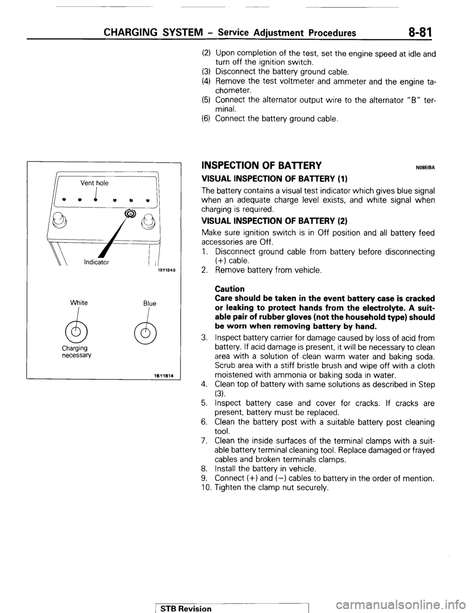
ll3Y1848 2. Remove battery from vehicle.
Caution
White
I Blue
I Care should be taken in the event battery case is cracked
or leaking to protect hands from the electrolyte. A suit-
able pair of rubber gloves (not the household type) should
be worn when removing battery by hand.
3. Inspect battery carrier for damage caused by loss of acid from
battery. If acid damage is present, it will be necessary to clean
area with a solution of clean warm water and baking soda.
Scrub area with a stiff bristle brush and wipe off with a cloth
moistened with ammonia or baking soda in water.
4. Clean top of battery with same solutions as described in Step
(3).
INSPECTION OF BATTERY NOBEIBA
VISUAL INSPECTION OF BATTERY (1)
The batten/ contains a visual test indicator which gives blue signal
when an adequate charge level exists, and white signal when
charging is required.
VISUAL INSPECTION OF BAlTERY (2)
Make sure ignition switch is in Off position and all battery feed
accessories are Off.
1. Disconnect ground cable from battery before disconnecting
(+) cable.
5. Inspect battery case and cover for cracks. If cracks are
present, battery must be replaced.
6. Clean the battery post with a suitable battery post cleaning
tool.
7. Clean the inside surfaces of the terminal clamps with a suit-
able battery terminal cleaning tool. Replace damaged or frayed
cables and broken terminals clamps.
8. Install the battery in vehicle.
9. Connect (+) and (-) cables to battery in the order of mention.
10. Tighten the clamp nut securely.
1 STB Revision
Page 102 of 284
8-82 CHARGING SYSTEM - Service Adjustment Procedures
BATTERY CHARGING NOEEICDZ
Caution
When batteries are being charged, an explosive gas forms
beneath the cover of each cell. Do not smoke near batteries
on charge or which have recently been charged. Do not
break live circuits at the terminals of the batteries on
charge. A spark will occur where the live circuit is broken.
Keep all open flames away from the battery.
Battery electrolyte temperature may temporarily be allowed to
rise to 55°C (131°F). Increase of electrolyte temperature above
55°C (131°F) is harmful to the battery, causing deformation of
battery cell, decrease in life of battery, etc.
CHARGE RATE
If the test indicator is white, the battery should be charged as
outlined below.
When the dot appears or when maximum charge shown
below is reached, charging should be stopped.
NOTE
If the indicator does not turn to blue even after the battery is
charged, the battery should be replaced; do not overcharge.
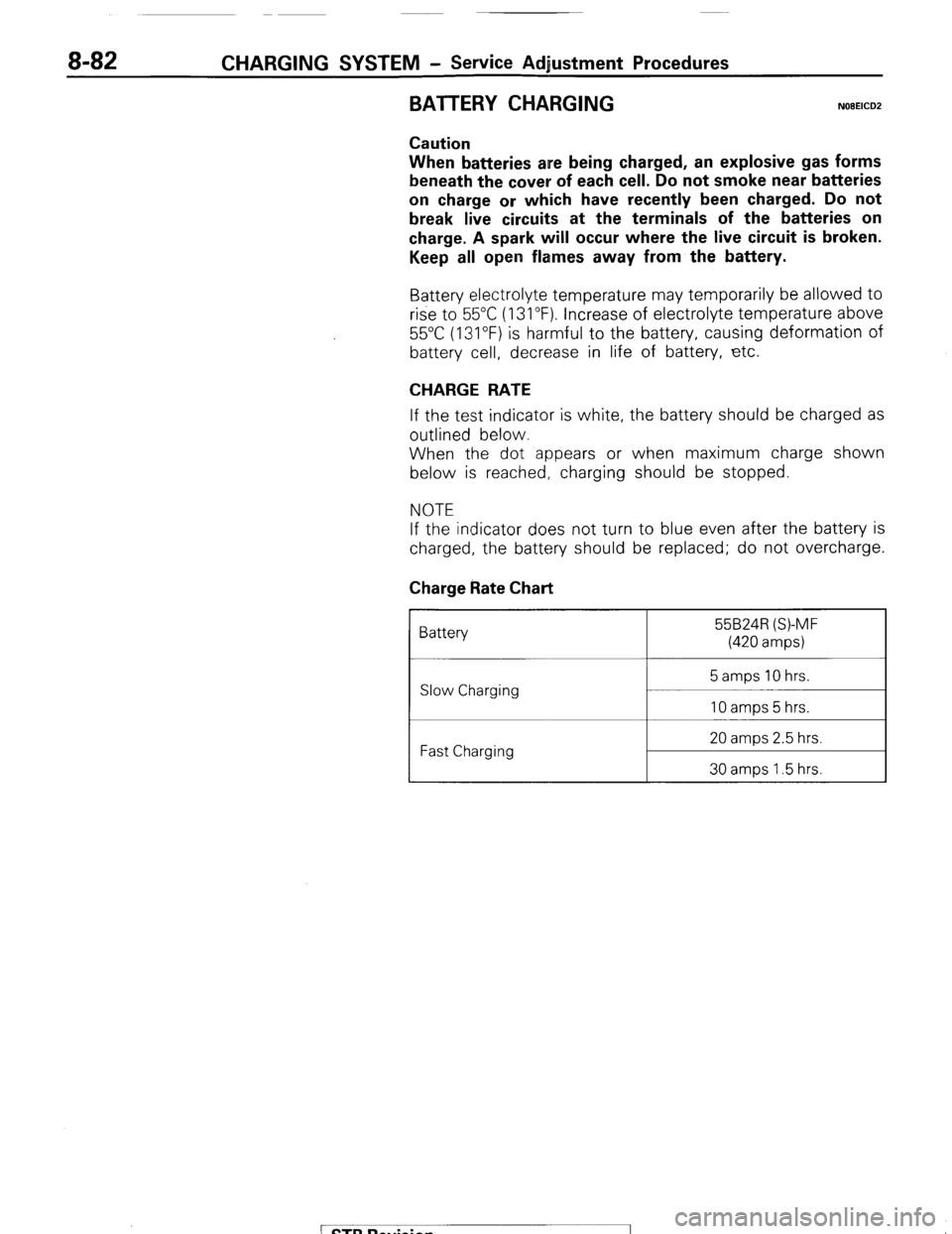
Charge Rate Chart
Battery 55B24R (S)-MF
(420 amps)
Slow Charging
Fast Charging 20 amps 2.5 hrs.
30 amps 1.5 hrs.
/ STB Revision
Page 103 of 284
CHARGING SYSWVI - Alternator 8-83
ALTERNATOR
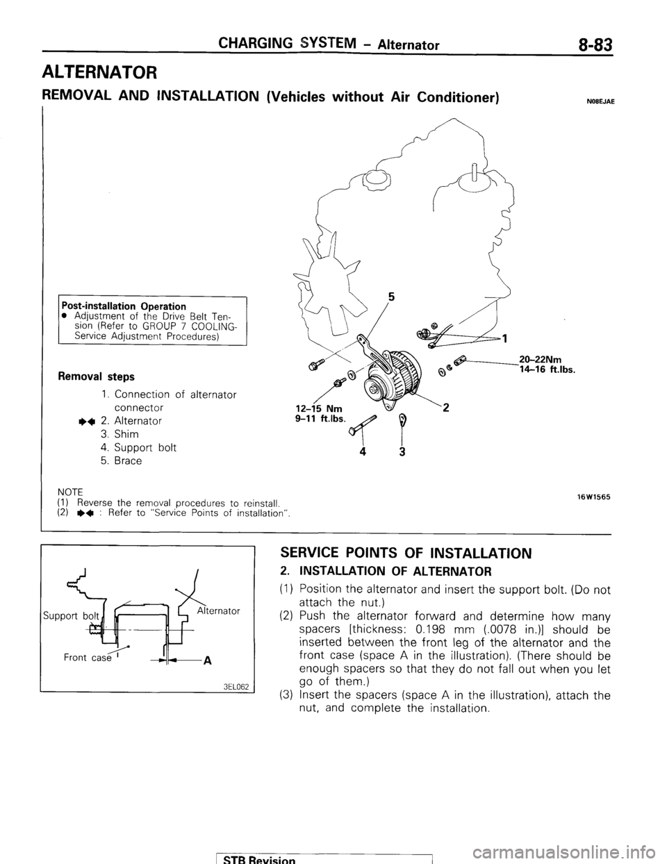
REMOVAL AND INSTALLATION (Vehicles without Air Conditioner) NOEEJAE
0 Adjustment of the Drive Belt Ten-
slon (Refer to GROUP 7 COOLING-
Service Adjustment Procedures)
Removal steps
1. Connection of alternator
connector
I)+ 2. Alternator
3. Shim
4.
Support bolt
5.
Brace
9-11 ft.lbs. 9
4
3
NOTE
(I) Reverse the removal procedures to reinstall.
(2) l * : Refer to “Service Points of installation”. 16W1565
SERVICE POINTS OF INSTALLATION
2. INSTALLATION OF ALTERNATOR
(1) Position the alternator and insert the support bolt. (Do not
attach the nut.)
(2) Push the alternator forward and determine how many
spacers [thickness: 0.198 mm (.0078 in.)] should be
inserted between the front leg of the alternator and the
front case (space A in the illustration). (There should be
enough spacers so that they do not fall out when you let
go of them.)
(3) Insert the spacers (space A in the illustration), attach the
nut, and complete the installation.
ST6 Revision
Page 104 of 284
8-84 CHARGING SYSTEM - Alternator
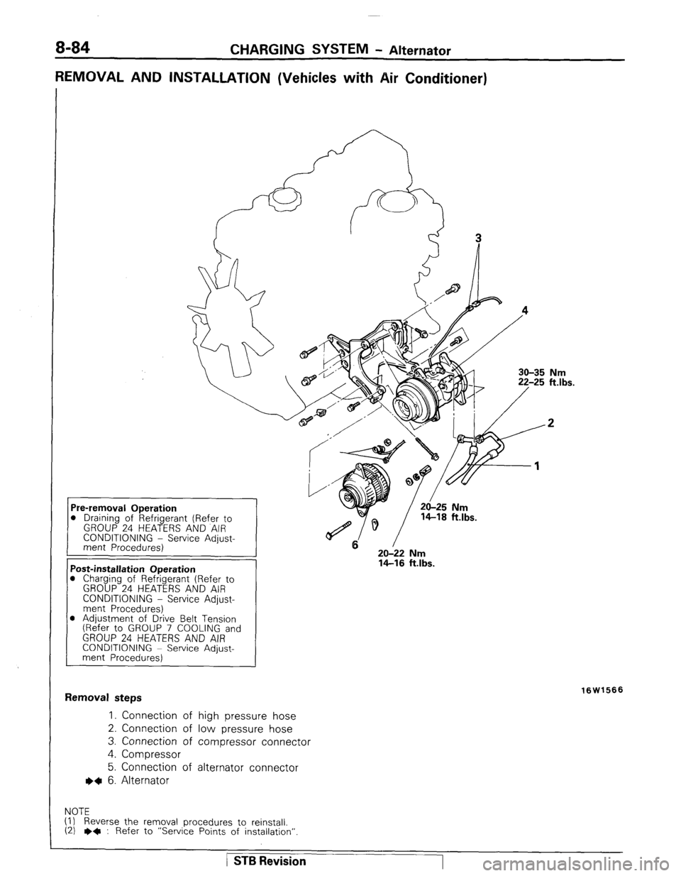
REMOVAL AND INSTALLATION (Vehicles with Air Conditioner)
30-35 Nm
20-22 Nm
14-16 ft.lbs. D Draining of Refrigerant (Refer to
CONDITIONING - Service Adjust-
1 ‘ost-installation Operation
1 Charging of Refrigerant (Refer to
GROUP 24 HEATERS AND AIR
CONDITIONING - Service Adjust-
ment Procedures)
D Adjustment of Drive Belt Tension
(Refer to GROUP 7 COOLING and
GROUP 24 HEATERS AND AIR
CONDITIONING ~ Service Adjust-
ment Procedures)
:emoval steps
1. Connection of high pressure hose
2. Connection of low pressure hose
3. Connection of compressor connector
4. Compressor
5. Connection of alternator connector
~~ 6. Alternator
OTE
) Reverse the removal procedures to reinstall.
I) e+ : Refer to “Service Points of installation” 16W1566
/ STB Revision
Page 105 of 284
CHARGING SYSTEM - Alternator 8-85
SERVICE POINTS OF INSTALLATION
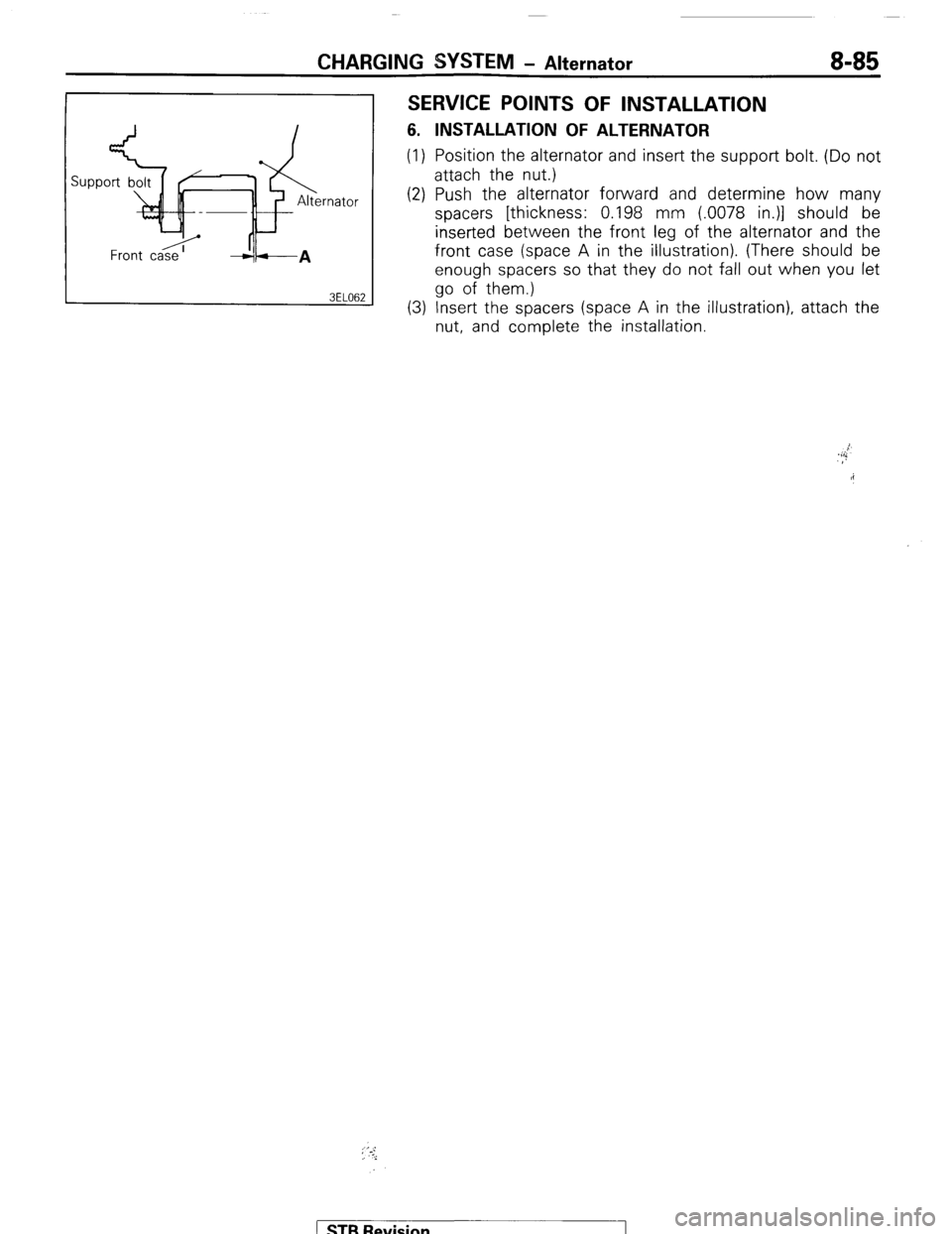
6. INSTALLATION OF ALTERNATOR
(1) Position the alternator and insert the support bolt. (Do not
attach the nut.)
(2) Push the alternator forward and determine how many
spacers [thickness: 0.198 mm (.0078 in.)] should be
inserted between the front leg of the alternator and the
front case (space A in the illustration). (There should be
enough spacers so that they do not fall out when you let
go of them.)
(3) Insert the spacers (space A in the illustration), attach the
nut, and complete the installation.
; ‘.-:,
i
) STB Revision
Page 106 of 284
CHARGING SYSTEM-Alternator
10 11 14
8 ? \I I
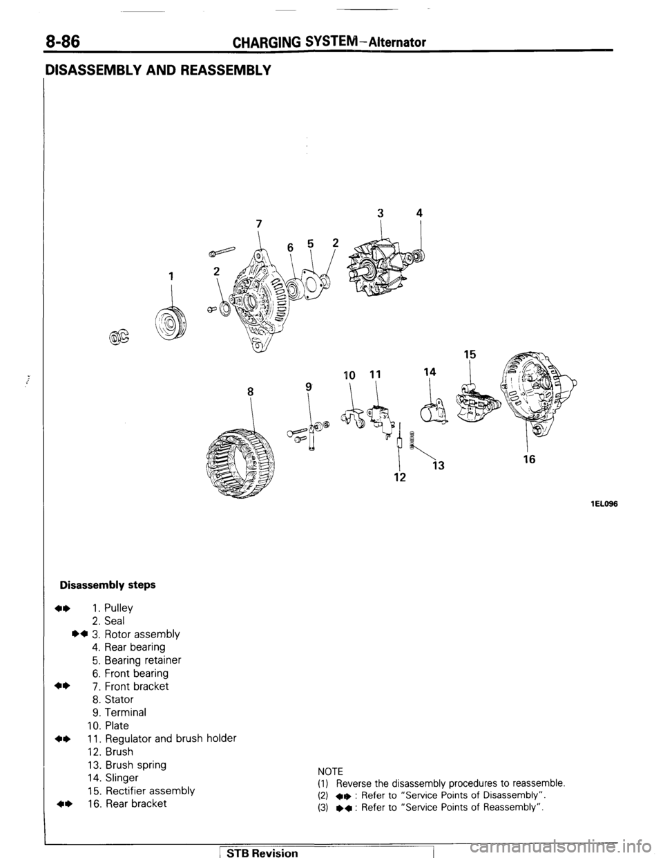
Disassembly steps
4* 1. Pulley
2. Seal
l a 3. Rotor assembly
4. Rear bearing
5. Bearing retainer
6. Front bearing
4*
7. Front bracket
8. Stator
9. Terminal
10. Plate
4* 11. Regulator and brush holder
12. Brush
13. Brush spring
14. Slinger
15. Rectifier assembly
4, 16. Rear bracket NOTE
(1) Reverse the disassembly procedures to reassemble.
(2) +e : Refer to “Service Points of Disassembly”.
(3) l
+ : Refer to “Service Points of Reassembly”.
1 EL666 1 STB Revision
Page 107 of 284
CHARGING SYSTEM-Alternator 8-87
6ELllt
SERVICE POINTS OF DISASSEMBLY
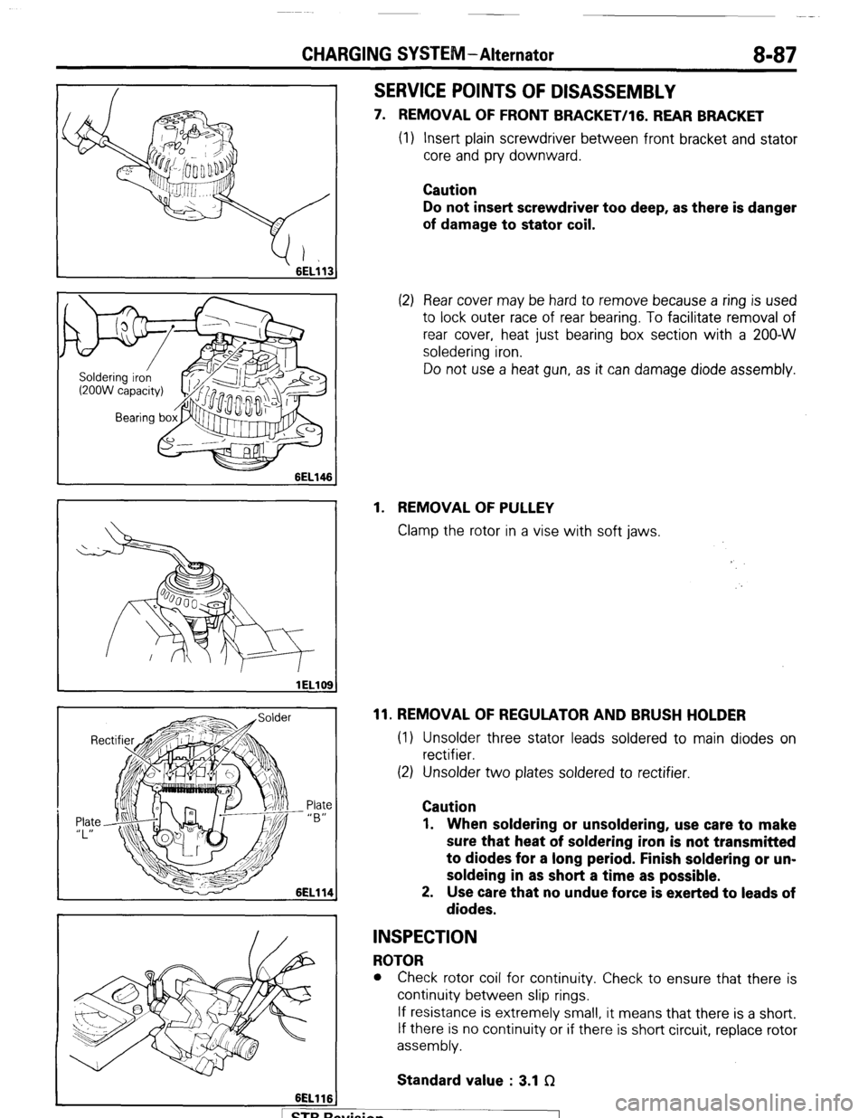
7. REMOVAL OF FRONT BRACKET/lG. REAR BRACKET
(1) Insert plain screwdriver between front bracket and stator
core and pry downward.
Caution
Do not insert screwdriver too deep, as there is danger
of damage to stator coil.
(2) Rear cover may be hard to remove because a ring is used
to lock outer race of rear bearing. To facilitate removal of
rear cover, heat just bearing box section with a 200-W
soledering iron.
Do not use a heat gun, as it can damage diode assembly.
1. REMOVAL OF PULLEY
Clamp the rotor in a vise with soft jaws.
11. REMOVAL OF REGULATOR AND BRUSH HOLDER
(1) Unsolder three stator leads soldered to main diodes on
rectifier.
(2) Unsolder two plates soldered to rectifier.
Caution
1. When soldering or unsoldering, use care to make
sure that heat of soldering iron is not transmitted
to diodes for a long period. Finish soldering or un-
soldeing in as short a time as possible.
2. Use care that no undue force is exerted to leads of
diodes.
INSPECTION
ROTOR
l Check rotor coil for continuity. Check to ensure that there is
continuity between slip rings.
If resistance is extremely small, it means that there is a short.
If there is no continuity or if there is short circuit, replace rotor
assembly.
Standard value : 3.1 f2
. . .
I 1 STB hewsion
Page 108 of 284
8-88 CHARGING SYSTEM-Alternator
6EL115
3ELOlO
lELll0
lELll1
A
) STBRc
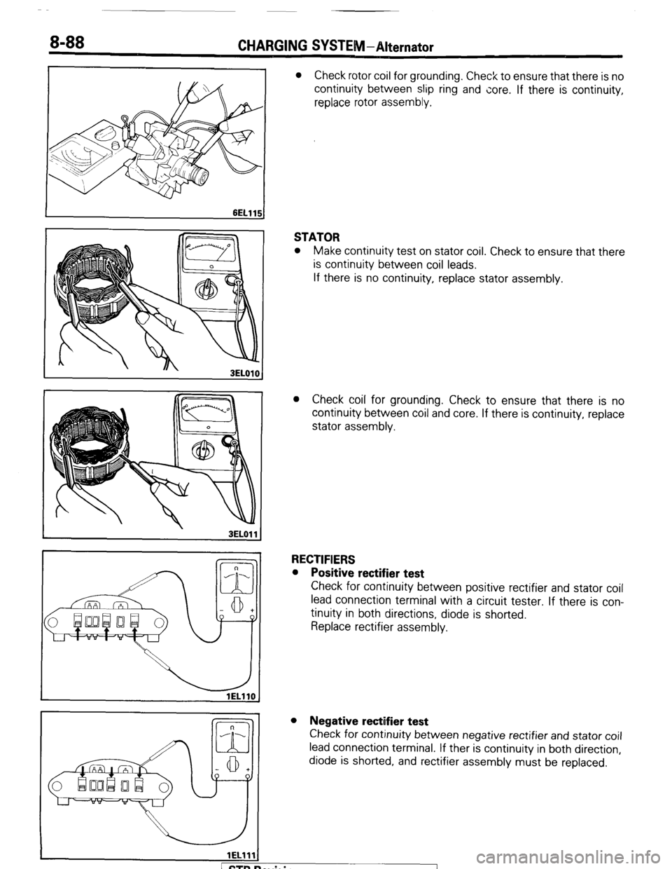
l Check rotor coil for grounding. Check to ensure that there is no
continuity between slip ring and core. If there is continuity,
replace rotor assembly.
STATOR
l Make continuity test on stator coil. Check to ensure that there
is continuity between coil leads.
If there is no continuity, replace stator assembly.
l Check coil for grounding. Check to ensure that there is no
continuity between coil and core. If there is continuity, replace
stator assembly.
RECTIFIERS
l Positive rectifier test
Check for continuity between positive rectifier and stator coil
lead connection terminal with a circuit tester. If there is con-
tinuity in both directions, diode is shorted.
Replace rectifier assembly.
l Negative rectifier test
Check for continuity between negative rectifier and stator coil
lead connection terminal. If ther is continuity in both direction,
diode is shorted, and rectifier assembly must be replaced.
evision
-7
Page 109 of 284
CHARGING SYSPE 8-89
lELll2
,
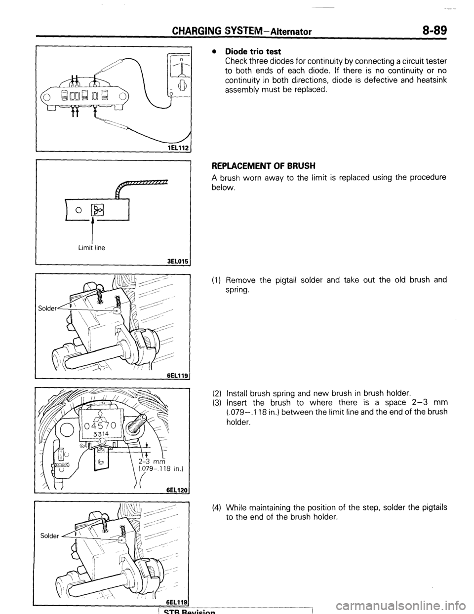
l Diode trio test
Check three diodes for continuity by connecting a circuit tester
to both ends of each diode. If there is no continuity or no
continuity in both directions, diode is defective and heatsink
assembly must be replaced.
REPLACEMENT OF BRUSH
A brush worn away to the limit is replaced using the procedure
below.
(1) Remove the pigtail solder and take out the old brush and
spring.
(2) Install brush spring and new brush in brush holder.
(3) Insert the brush to where there is a space 2-3 mm
(.079-,118 in.) between the limit line and the end of the brush
holder.
(4) While maintaining the position of the step, solder the pigtails
to the end of the brush holder.
1 STB Revision
1
Page 110 of 284
8-90 CHARGING SYSTEM-Alternator
Rear bracket Wire
6EL122
6EL123 I
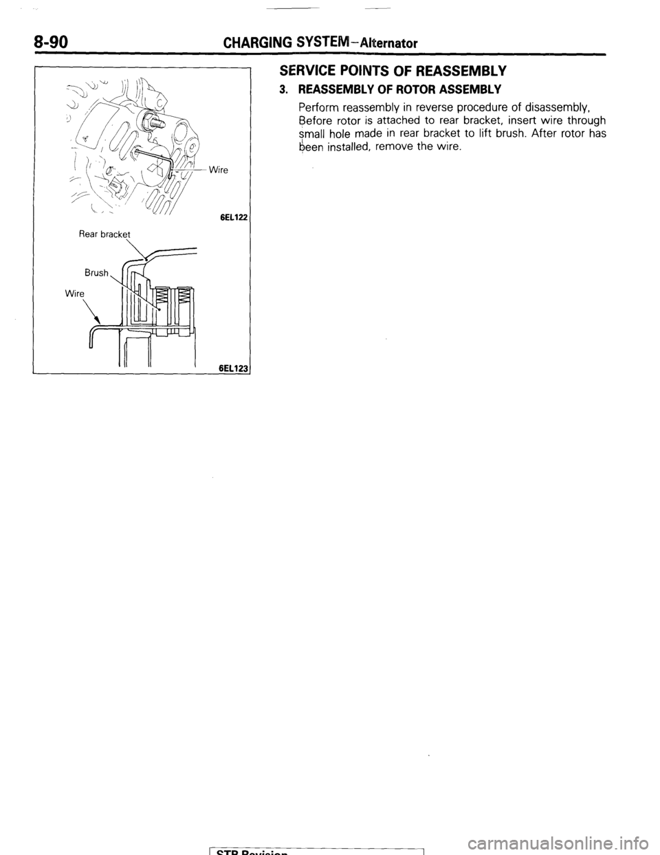
SERVICE POINTS OF REASSEMBLY
3. REASSEMBLY OF ROTOR ASSEMBLY
Perform reassembly in reverse procedure of disassembly,
Before
rotor is attached to rear bracket, insert wire through
small hole made in rear bracket to lift brush. After rotor has
6een installed, remove the wire.
STB Revision